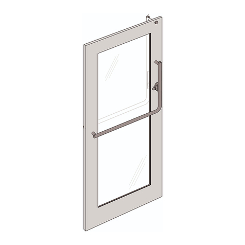
Assa Abloy PDU8000 Series User manual

IMPORTANT: PLEASE READ BEFORE INSTALLING THE PANIC DEVICE
The following instructions will decrease your chances of experiencing problems during
the installation and ensure a smooth, trouble-free operation of the Panic Device.
PDU8000 Series Panic Device
Copyright © 2017-2022, ASSA ABLOY Inc. All rights reserved. Reproduction in whole or in part
without the express written permission of ASSA ABLOY Inc. is prohibited.

Copyright © 2017-2022, ASSA ABLOY Inc. All rights reserved. Reproduction in whole
or in part without the express written permission of ASSA ABLOY Inc. is prohibited.
1
Table of Contents
1. Introduction ...................................................................................................................................................................................
1.1 Description ...........................................................................................................................................................................
1.2 Parts List ................................................................................................................................................................................
1.3 Tools and Supplies ...............................................................................................................................................................
1.4 Dogging Feature ...................................................................................................................................................................
2. Instructions for Rail Mount Doors ............................................................................................................................................
2.1 Detailed Parts List ...............................................................................................................................................................
2.2 Removal from Packaging ....................................................................................................................................................
2.2.1 Introduction ............................................................................................................................................................
2.2.2 Remove Panic Device from Shipping Board .......................................................................................................
2.2.3 Remove Horizontal Door Mount ........................................................................................................................
2.2.4 Remove Horizontal Door Mount (Deco End Cap Option) ...............................................................................
2.2.5 Remove Vertical Door Mount ...............................................................................................................................
2.2.6 Remove Actuator Post Assembly ...........................................................................................................................
2.3 Panic Device Installation .....................................................................................................................................................
2.3.1 Install Panic Device on Rail Mount Door ............................................................................................................
2.3.2 Install Door Bushings .............................................................................................................................................
2.3.3 Install Alignment Bushing .....................................................................................................................................
2.3.4 Install Mating Pull .....................................................................................................................................................
2.3.5 Install Actuator Post Assembly .............................................................................................................................
2.3.6 Install Vertical Door Mount ...................................................................................................................................
2.3.7 Install Horizontal Door Mount .............................................................................................................................
2.3.8 Install Horizontal Door Mount (Deco End Cap Option) .....................................................................................
2.3.9 Install Panic Device on Rail Mount Door .............................................................................................................
2.3.10 Horizontal End Threadlocker and Lube Application ......................................................................................
2.3.11 Align Actuator Gauge ...........................................................................................................................................
3. Instructions for All Glass Doors ....................................................................................................................................................
3.1 Detailed Parts List .................................................................................................................................................................
3
3
3
3
4
5
5
7
7
7
8
8
9
9
10
10
10
10
11
11
12
13
13
14
15
15
17
17

Copyright © 2017-2022, ASSA ABLOY Inc. All rights reserved. Reproduction in whole
or in part without the express written permission of ASSA ABLOY Inc. is prohibited. 2
Table of Contents (Continued)
3.2 Removal from Packaging .....................................................................................................................................................
3.2.1 Introduction ............................................................................................................................................................
3.2.2 Remove Panic Device from Shipping Board ......................................................................................................
3.2.3 Remove Horizontal Door Mount ..........................................................................................................................
3.2.4 Remove Horizontal Door Mount (Deco End Cap Option) ..............................................................................
3.2.5 Remove Vertical Door Mount ...........................................................................................................................
3.2.6 Remove Actuator Post Assembly .........................................................................................................................
3.3 Panic Device Installation ..........................................................................................................................................................
3.3.1 Install Panic Device on All Glass Door .................................................................................................................
3.3.2 Install Door Bushings ..............................................................................................................................................
3.3.3 Install Alignment Bushing ........................................................................................................................................
3.3.4 Install Mating Pull ...................................................................................................................................................
3.3.5 Install Actuator Post Assembly ...........................................................................................................................
3.3.6 Install Vertical Door Mount ..................................................................................................................................
3.3.7 Install Horizontal Door Mount ..............................................................................................................................
3.3.8 Install Horizontal Door Mount (Deco End Cap Option) ...................................................................................
3.3.9 Install Panic Device on All Glass Door .................................................................................................................
3.3.10 Horizontal End Threadlocker and Lube Application .......................................................................................
3.3.11 Align Actuator Gauge .........................................................................................................................................
4. Strike Installation ..........................................................................................................................................................................
4.1 Header Preparation for Single and Double Manual Strikes with Adjustable Door Stops .......................................
4.2 Header Preparation for Folger Adams 310-1 Single and Double Electrical Strikes with Adjustable Door Stops .......
4.3 Header Preparation for HES 1600 Single and Double Electric Strikes with Adjustable Door Stops ...........................
5. Latch / Adjustable Door Stops Adjustment ................................................................................................................................
5.1 Installation and Adjustment of Door Stop-Strike ..........................................................................................................
5.2 Latch Adjustment for Proper Engaging with the Strike .................................................................................................
5.3 Cylinder Recommendations ....................................................................................................................................................
6. Cleaning and Maintenance ................................................................................................................................................................
6.1 General Maintenance Instructions .....................................................................................................................................
6.2 Finish Cleaning Instructions ................................................................................................................................................
6.3 Mechanical Maintenance .....................................................................................................................................................
19
19
19
20
20
21
21
22
22
22
22
23
23
24
25
25
26
27
27
28
28
30
32
34
34
36
37
38
38
38
39
Copyright © 2017-2022, ASSA ABLOY Inc. All rights reserved. Reproduction in whole
or in part without the express written permission of ASSA ABLOY Inc. is prohibited.
1. Introduction
3
• The PDU8000 Series Panic Device offers superior functionality for egress and security needs.
• The Panic Device has an aesthetically pleasing design that is available in two configurations: one for Rail Mount Doors
and one for All Glass Doors.
• Depending on configuration, the system could include a Dogging Feature. Refer to Dogging Feature (Introduction, page 4).
• Please read the Installation Instructions in this manual carefully before installing the Panic Device.
• If you have questions, please contact us at (800) 458-2424.
Description1.1
• The tools and supplies listed below are necessary to complete the installation of the Panic Device.
• Each configuration of the Panic Device has its own unique parts list . Please refer to the Detailed Parts List section for
the applicable parts lists shown below.
Parts List1.2
Tools and Supplies
1.3
• Detailed Parts List - Rail Mount Doors: Refer to Section 2.1.
• Detailed Parts List - All Glass Doors: Refer to Section 3.1.
Tools
• Allen wrenches: 5/64", 5/32", 1/8", 3/16", 1/4"
• Latch and Actuator Gauge
• Spanner Wrench
• Wrench: 7/16"
• #2 Philips Head Screwdriver
Supplies included in kit
• Threadlocker
• Synthetic Multi-Purpose Grease
• Latch and Actuator Gauge
• Extra Door Bushings
Supplies Needed (not included in kit)
• Soft Cloth

Copyright © 2017-2022, ASSA ABLOY Inc. All rights reserved. Reproduction in whole
or in part without the express written permission of ASSA ABLOY Inc. is prohibited. 4
Figure 1-1
Dogged Position
Figure 1-2
Un-dogged Position
Dog Button
Dog Button
• The Dogging Feature is located on the bottom of the Panic Device Assembly vertical tube, directly under
the Actuator Post Assembly.
• Engage the Horizontal Crash Bar and slide the Dog Button to the up position.
• The Panic Device Assembly is dogged when the Dog Button is in the up position. Refer to Figure 1-1.
• The Panic Device Assembly is un-dogged when the Dog Button is in the down position. Refer to Figure 1-2.
1.4 Dogging Feature

Copyright © 2017-2022, ASSA ABLOY Inc. All rights reserved. Reproduction in whole
or in part without the express written permission of ASSA ABLOY Inc. is prohibited.
2.1 Detailed Parts List
5
10
11
13
14
2
7
7
5
3
6
8
15
16
17
18
19
20
22
25
9
1
10
7
11
12
21
24
26
27
29
4
23
27
28
12
15
A
A
Panic Device Deco End
2. Instructions for Rail Mount Doors

Copyright © 2017-2022, ASSA ABLOY Inc. All rights reserved. Reproduction in whole
or in part without the express written permission of ASSA ABLOY Inc. is prohibited. 6
1Panic Device Assembly .................................................
2Vertical Door Mount Assembly .................................
3Actuator Post-Cylinder Housing Assembly ............
4Horizontal Door Mount Assembly ..........................
5Mating Pull Assembly ....................................................
6Adapter Block .................................................................
7Socket Cap Screw (5/16"-18) ....................................
8Interior Pivot Bracket Post .......................................
9Set Screw (8-32) ..............................................................
qAdapter Block Post .......................................................
wNylon Lock Nut (Not Reused) ...................................
eSet Screw Pin (1/4"-20) .................................................
rMating Pull-Cylinder Housing Assembly ...............
tCylinder Housing ...........................................................
yDoor Gasket .....................................................................
Description Quantity
uDoor Bushing ....................................................................
iActuator Post Assembly .................................................
oPush Rod ............................................................................
pSpring Tube-Spring ..........................................................
aFlat Head Socket Cap Screw (1/4"-20) .....................
sLatch and Actuator Gauge ...........................................
dPlastic Washer ..................................................................
fAlignment Bushing .............................................................
gMetal Washer ...................................................................
hConehead Union (5/16"-18) ........................................
jInterior Horizontal Post .................................................
kSet Screw (1/4"-20) ........................................................
lDeco End Cap ...................................................................
;Stud (5/16"-18) ................................................................
Description Quantity
4
1
1
1
1
1
2
1
1
1
1
2
1
1
1
1
1
1
1
1
3
1
1
2
2
2
1
1
2

Copyright © 2017-2022, ASSA ABLOY Inc. All rights reserved. Reproduction in whole
or in part without the express written permission of ASSA ABLOY Inc. is prohibited.
2.2 Removal from Packaging - Rail Mount Doors
7
Introduction2.2.1
2
Vertical Door Mount Assembly
3
Actuator Post-Cylinder Housing Assembly
4
Horizontal Door Mount Assembly
Shipping Board
2
3
4
• The Panic Device Assembly comes mounted on a Shipping Board inside
a shipping crate.
• Before removing from the Shipping Board, make sure that the device is
in the un-dogged position. Refer to Introduction, page 4.
• Most of the hardware will be reused. Do not discard any parts at this time.
• Remove the Shipping Board from the shipping crate.
• Make sure that the Vertical Door Mount Assembly 2, Actuator Post-
Cylinder Housing Assembly 3, and Horizontal Door Mount Assembly 4
are still attached to the Shipping Board when removing from the crate.
Remove Panic Device from Shipping Board
eSet Screw Pin
1Panic Device Assembly
kSet Screws (1/4"-20)
2.2.2
• Remove the Set Screw Pin efrom the Panic Device Assembly 1.
• Loosen the two Set Screws (1/4"-20) kon the free end. The Set Screws
(1/4"-20) kare not removed in this step.
• Pull the Panic Device 1away from the Shipping Board by tilting the device.
Shipping Board
12
1
A
B
C
AC
27
B
12

Copyright © 2017-2022, ASSA ABLOY Inc. All rights reserved. Reproduction in whole
or in part without the express written permission of ASSA ABLOY Inc. is prohibited. 8
Remove Horizontal Door Mount (Deco End Cap Option)
2.2.4
lDeco End Cap
hConehead Union (5/16"-18)
dPlastic Washer (x2)
gMetal Washer
fAlignment Bushing
• Unscrew and remove the Conehead Union (5/16"-18) h.
• Remove the Deco End Cap l.
• Remove the two Plastic Washers d, Metal Washer g,
and Alignment Bushing f.
22
23
Shipping Board
28
22
25
24
5
25
Shipping Board
24
22
23
22
5Mating Pull Assembly
hConehead Union (5/16"-18)
dPlastic Washer (x2)
gMetal Washer
fAlignment Bushing
Remove Horizontal Door Mount2.2.3
• Unscrew and remove the Conehead Union (5/16"-18) h.
• Remove the two Plastic Washers d, Metal Washer g, and Alignment Bushing f.

Copyright © 2017-2022, ASSA ABLOY Inc. All rights reserved. Reproduction in whole
or in part without the express written permission of ASSA ABLOY Inc. is prohibited.
9
Remove Vertical Door Mount2.2.5
9Set Screw (8-32)
8Interior Pivot Bracket Post
7Socket Cap Screw (5/16"-18) (x3)
5Mating Pull Assembly
wNylon Lock Nuts (Not Reused)
6Adapter Block
• Unscrew the Set Screw (8-32) 9enough to remove the Interior
Pivot Bracket Post 8.
• Remove the Interior Pivot Bracket Post 8.
• Remove the Socket Cap Screw (5/16"-18) 7from the Mating Pull
Assembly 5.
• Remove the two Socket Cap Screws (5/16"-18) 7and the Nylon Lock
Nuts wfrom the Adapter Block 6.
7
10
11
7
9
5
6
Shipping Board
7
10
11
8
Remove Actuator Post Assembly
2.2.6
aFlat Head Socket Cap Screw (1/4"-20)
iActuator Post Assembly
oPush Rod
pSpring Tube-Spring
5Mating Pull Assembly
uDoor Bushing
• Remove the Flat Head Socket Cap Screw (1/4"-20) a.
• Remove the Actuator Post Assembly i, Push Rod o, and
Spring Tube-Spring pfrom the Shipping Board.
• Hold the Mating Pull 5in place while removing the Actuator
Post Assembly i.
• Remove the Mating Pull 5from the Shipping Board.
• Remove the Door Bushing u.
CAUTION: Make sure to contain the Spring inside the Spring Tube-Spring p.
20
1718
19
5
16

Copyright © 2017-2022, ASSA ABLOY Inc. All rights reserved. Reproduction in whole
or in part without the express written permission of ASSA ABLOY Inc. is prohibited.
2.3 Panic Device Installation - Rail Mount Doors
10
• Lay the glass flat with the exterior side facing down on a pair of saw horses.
• Make sure that the Door Rails are installed per manufacturer’s specifications.
Door Rail
2
3
4
2.3.1
2
Vertical Door Mount Assembly
3
Actuator Post-Cylinder Housing Assembly
4
Horizontal Door Mount Assembly
Install Panic Device on Rail Mount Door
• You can adjust the Alignment Bushing fby rotating it 360 degrees.
• Make the necessary adjustment to get equal spacing between
the sides of the Actuator Post Assembly iand the tube opening.
• If there is friction against the right side, adjust the opening of
the Alignment Bushing fto the right. Refer to Figure B1.
• If there is friction against the left side, adjust the opening of the
Alignment Bushing fto the left. Refer to Figure B2.
• There are four Door Bushings uin each package.
• Below are the different configurations of the Door Bushings u.
• Choose the Door Bushings uconfiguration that best fits your
Panic Device Assembly Installation and centers the actuator post in
the tube opening.
• Each Door Bushing ucontains 6 ribs.
• Removal of the rib material may be necessary to ensure a proper fit.
AB
C D
OR OR OR
OROR
Ribs
Ribs
Install Door Bushings
2.3.2 Install Alignment Bushing
2.3.3
Figure B1
Figure B2

Copyright © 2017-2022, ASSA ABLOY Inc. All rights reserved. Reproduction in whole
or in part without the express written permission of ASSA ABLOY Inc. is prohibited.
11
Install Mating Pull2.3.4
5Mating Pull Assembly
rMating Pull-Cylinder Housing Assembly
yDoor Gasket
uDoor Bushing
13
15
16
Cylinder Housing
Assembly Post
Glass Door
5
• Place the Mating Pull Assembly 5on the Door.
• Install the Mating Pull-Cylinder Housing Assembly rwith the Door Gasket y
through the holes in the Glass Door.
• Make sure that the posts that are sticking out from the Cylinder Housing
Assembly rgo through the Door Bushing u.
i Actuator Post Assembly
t Cylinder Housing
o Push Rod
a Flat Head Socket Cap Screw (1/4"-20)
p Spring Tube-Spring
Install Actuator Post Assembly
2.3.5
18
20
19
5
14
Glass Door
17
• Install the Actuator Post Assembly ion top of the opening in the Glass
Door to attach to the Cylinder Housing t.
• Make sure that the Push Rod ogoes through the bottom hole.
• Apply a small drop of Threadlocker to the threads of the Flat Head Socket
Cap Screw (1/4"-20) a.
• Install the Flat Head Socket Cap Screw (1/4"-20) aand secure until tight.
CAUTION: Make sure that the Spring Tube-Spring pand the Push Rod o
are inserted into the Actuator Post Assembly i.

Copyright © 2017-2022, ASSA ABLOY Inc. All rights reserved. Reproduction in whole
or in part without the express written permission of ASSA ABLOY Inc. is prohibited. 12
Install Vertical Door Mount2.3.6
6 Adapter Block
5 Mating Pull Assembly
7 Socket Cap Screw (5/16"-18)
q Adapter Block Posts
8 Interior Pivot Bracket Post
9 Set Screw (8-32)
• Position the Adapter Block 6on the inside of the Door Rail.
• Install the Mating Pull Assembly 5through the Door Rail and up against
the Adaptor Block 6.
• Apply a small drop of Threadlocker to the threads of the Socket Cap Screw
(5/16"-18) 7.
• Attach the Adaptor Block 6to the Mating Pull Assembly 5with the
Socket Cap Screw (5/16"-18) 7.
• Install the Interior Pivot Bracket Post 8on the Adaptor Block 6. Make
sure that the Interior Pivot Bracket Post 8is vertical after it is installed.
• Adjust the Adapter Block Posts quntil the Interior Pivot Bracket Post 8
is centered vertically.
• Align the Interior Pivot Bracket Post 8until the slot can be seen on the
threads of the post. This is where the Set Screw (8-32) 9will install.
• Make sure to align the hole on the Door Rail with the hole on the
Adapter Block 6.
• Apply a small drop of Threadlocker to the threads of the Set Screw (8-32) 9.
• Install the Set Screw (8-32) 9.
• Apply Synthetic Grease to the inside of the hole of the Interior Pivot Bracket
Post 8.
Door Rail
56
8
7
9
Door Rail
10
Pivot Bracket Post hole
(synthetic grease)
10

Copyright © 2017-2022, ASSA ABLOY Inc. All rights reserved. Reproduction in whole
or in part without the express written permission of ASSA ABLOY Inc. is prohibited.
13
f Alignment Bushing
5 Mating Pull Assembly
; Stud (5/16"-18)
g Metal Washer
h Conehead Union (5/16"-18)
d Plastic Washer (x2)
Install Horizontal Door Mount
2.3.7
5
22
24
23
25
22
Glass Door
29
• Install the Alignment Bushing fin the hole of the Glass Door.
• Position the Mating Pull Assembly 5against the exterior side of the Glass Door.
• Apply a small drop of Threadlocker to the threads of the Stud (5/16"-18) ;.
• Slide the Metal Washer gonto the Stud (5/16"-18) ;until it sits against
the Conehead Union (5/16"-18) hon the interior side of the door.
• Slide one Plastic Washer donto the Stud (5/16"-18) ;so it sits against the
Metal Washer gon the interior side of the door.
• Slide the Conehead Union (5/16"-18) hwith the Plastic Washer dand
the Metal Washer gthrough the Alignment Bushing fin the hole in the Door.
• Slide the other Plastic Washer donto the Stud (5/16"-18) ;on the
outside of the Door.
• Screw the Conehead Union (5/16"-18) hand the Stud (5/16"-18) ;into
the Mating Pull Assembly 5Post until tight. Make sure that the Metal
Washer gdoes not touch the Glass Door.
f Alignment Bushing
5 Mating Pull Assembly
d Plastic Washer (x2)
h Conehead Union (5/16"-18)
; Stud (5/16"-18)
l Deco End Cap
Install Horizontal Door Mount (Deco End Cap Option)2.3.8
• Install the Alignment Bushing fin the hole of the Glass Door.
• Apply a small drop of Threadlocker to the threads of the Stud (5/16"-18) ;.
• Insert the Stud (5/16"-18) ;into the Deco End Cap l.
• Place one Plastic Washer donto the Stud (5/16"-18) ;until it's up against
the Deco End Cap l.
• Slide the Stud (5/16"-18) ;with the Deco End Cap lthrough the Alignment
Bushing fin the hole in the Door on the exterior side of the door.
• Place one Plastic Washer dand the Metal Washer gonto the Stud (5/16"-18) ;
on the interior side of the Door.
• Apply a small drop of Threadlocker to the threads of the Stud (5/16"-18) ;.
• Screw the Conehead Union (5/16"-18) honto the Stud (5/16"-18) ;on the
interior side of the Door.
22
23
Glass Door
28
22
25
29

Copyright © 2017-2022, ASSA ABLOY Inc. All rights reserved. Reproduction in whole
or in part without the express written permission of ASSA ABLOY Inc. is prohibited. 14
6 Adapter Block
8 Interior Pivot Bracket Post
1 Panic Device Assembly
e Set Screw Pin (1/4"-20)
7 Socket Cap Screw (5/16"-18) (x2)
5 Mating Pull Assembly
h Conehead Union (5/16"-18)
k Set Screws (1/4"-20)
Install Panic Device on Rail Mount Door
2.3.9
Door Rail
7
6
8
1
7
• Push the Adaptor Block 6forward to expose the Interior Pivot Bracket
Post 8.
• Use the tilt method to install the Panic Device Assembly 1. Refer to
Section 2.2.2 on page 9.
• Install the Panic Device Assembly 1on the Interior Pivot Bracket Post 8
that is attached to the Adaptor Block 6.
• Apply a small drop of Threadlocker to the threads of the Set Screw Pin
(1/4"-20 e.
• Install the Set Screw Pin (1/4"-20) e.
• Align the Adaptor Block 6with threaded holes (5/16"-18) inside of the
Door Rail.
• Apply a small drop of Threadlocker to the threads of the Socket Cap
Screws (5/16"-18) 7.
• Install the Socket Cap Screws (5/16"-18) 7and secure until tight.
• Apply a small drop of Threadlocker to the threads of the Set Screws
(1/4"-20) k.
• Tighten down both Set Screws (1/4"-20) k.
A
A
B
27
25
27
Glass Door
5
B
12
C
C

Copyright © 2017-2022, ASSA ABLOY Inc. All rights reserved. Reproduction in whole
or in part without the express written permission of ASSA ABLOY Inc. is prohibited.
15
12
1
12
Glass Door
26 26
1
Synthetic
Multi-Purpose
Grease
Glass Door
e Set Screw Pin
1 Panic Device Assembly
j Interior Horizontal Post
Horizontal End Threadlocker and Lube Application2.3.10
• Remove the Set Screw Pin eand move the Panic Device Assembly 1
to the side to allow access to the Interior Horizontal Post jhole.
• Apply Synthetic Multi-Purpose Grease (pea size) to the inside of the hole
of the Interior Horizontal Post j.
• Install the Panic Device Assembly 1Handle back on the Panic Device
Assembly 1.
• Apply a small drop of Threadlocker to the threads of the
Set Screw Pin e.
• Install the Set Screw Pin e.
s Latch and Actuator Gauge
i Actuator Post Assembly
21
17 17
21
Align Actuator Gauge2.3.11
• Install the Latch and Actuator Gauge sin the bottom of the Actuator
Post Assembly i.
• If the Latch and Actuator Gauge scannot be installed, the alignment
must be adjusted.
• Realign the Panic Device Assembly as necessary. Refer to Section 2.3.2,
Install Door Bushings.
• Do not operate the Panic Device if the Latch and Actuator Gauge s
does not fit.

Copyright © 2017-2022, ASSA ABLOY Inc. All rights reserved. Reproduction in whole
or in part without the express written permission of ASSA ABLOY Inc. is prohibited. 16
Notes

Copyright © 2017-2022, ASSA ABLOY Inc. All rights reserved. Reproduction in whole
or in part without the express written permission of ASSA ABLOY Inc. is prohibited.
17
10
11
2
8
5
3
4
7
12
13
15
16
17
20
19
22
24
9
1
9
18
21
23
24
6
6A
26
25
A
Panic Device Deco End
A
14
12
3.1 Detailed Parts List
3. Instructions for All Glass Doors

Copyright © 2017-2022, ASSA ABLOY Inc. All rights reserved. Reproduction in whole
or in part without the express written permission of ASSA ABLOY Inc. is prohibited.
1Panic Device Assembly ......................................................
2Vertical Door Mount Assembly ......................................
3Actuator Post-Cylinder Housing Assembly ..............
4Horizontal Door Mount Assembly ................................
5Mating Pull Assembly .........................................................
6Exterior Pivot Bracket Assembly ....................................
6Pivot Bracket Bushing .................................................
7Interior Pivot Bracket Assembly ....................................
8Flat Head Socket Screw (5/16"-18) ..............................
9Set Screw Pin (1/4"-20) ..................................................
qMating Pull-Cylinder Housing Assembly ...................
wCylinder Housing ................................................................
eDoor Gasket .........................................................................
rDoor Bushing ......................................................................
6A
18
Description Quantity
1
1
1
1
1
1
1
1
1
2
1
1
2
4
tActuator Post Assembly ..................................................
yPush Rod ...............................................................................
uSpring Tube-Spring ...........................................................
iFlat Head Socket Cap Screw (1/4"-20) ........................
oLatch and Actuator Gauge .............................................
pPlastic Washer ....................................................................
aAlignment Bushing ...........................................................
sMetal Washer .....................................................................
dConehead Union (5/16"-18) .........................................
fInterior Horizontal Post ..................................................
gSet Screw (1/4"-20) .........................................................
hDeco End Cap .....................................................................
jStud (5/16"-18) ..................................................................
Description Quantity
1
1
1
1
1
2
1
1
1
1
2
1
1

Copyright © 2017-2022, ASSA ABLOY Inc. All rights reserved. Reproduction in whole
or in part without the express written permission of ASSA ABLOY Inc. is prohibited.
3.2 Removal from Packaging - All Glass Doors
19
Shipping Board
2
3
4
Introduction3.2.1
2
Vertical Door Mount Assembly
3
Actuator Post-Cylinder Housing Assembly
4
Horizontal Door Mount Assembly
• The Panic Device Assembly comes mounted on a Shipping Board inside
a shipping crate.
• Before removing from the Shipping Board, make sure that the device is
in the un-dogged position. Refer to Introduction, page 4.
• Most of the hardware will be reused. Do not discard any parts at this time.
• Remove the Shipping Board from the shipping crate.
• Make sure that the Vertical Door Mount Assembly 2, Actuator Post-
Cylinder Housing Assembly 3, and Horizontal Door Mount Assembly 4
are still attached to the Shipping Board when removing from the crate.
Remove Panic Device from Shipping Board
9Set Screw Pin
1Panic Device Assembly
gSet Screws (1/4"-20)
3.2.2
• Remove the Set Screw Pin 9from the Panic Device Assembly 1.
• Loosen the two Set Screws (1/4"-20) gon the free end. The Set Screws
(1/4"-20) gare not removed in this step.
• Pull the Panic Device 1away from the Shipping Board by tilting the device.
Shipping Board
9
1
A
B
C
AC
24
B
9
Other manuals for PDU8000 Series
1
Table of contents
Languages:
Other Assa Abloy Safety Equipment manuals

Assa Abloy
Assa Abloy SARGENT Beacon User manual

Assa Abloy
Assa Abloy 179A User guide

Assa Abloy
Assa Abloy PDU8500 Series User manual

Assa Abloy
Assa Abloy 179B User guide

Assa Abloy
Assa Abloy SARGENT 57 Series User manual

Assa Abloy
Assa Abloy SARGENT 9400 Series User manual

Assa Abloy
Assa Abloy Securitron EEB2 Manual