Webtool HCV155 Maintenance manual

HOSE/UMBILICAL CUTTER HCV155
PRODUCT CODE No. 980217
INSTRUCTIONS FOR INSTALLATION,
OPERATION & MAINTENANCE
Revision 3 issue 3. Modification No. 20644 Date 17TH. Oct 2013
© Copyright Allspeeds Holdings Ltd.
This document must not be modified in any way.

Page 2of 17
Description
The HCV155 is a double acting tool primarily intended for use on umbilical cable and hose and
will cut up to 155mm diameter. It may be used on alternative materials, such as electrical power
or communication cables, again up to a maximum of 155mm diameter. Where small diameters
are to be cut, every effort should be made to place the material centrally along the anvil to
minimize offset loading. The cutter is not designed to cut wire rope.
1. SAFETY
Before operation, read and understand this operations manual.
Whilst the tool is intended for remote or local operation sub-sea, there is no reason why it
should not be used above surface.
Ensure that the tool, hoses and pump are in good condition and properly connected.
Ensure that suitable pressure regulation equipment is used and that the unit is not subjected to
pressures higher than those stated in section 3
In all cases, where an operator is present, the safety aspects must be reviewed before the
cutting operation is commenced.
No attempt should be made to cut any material that is under tension.
Ensure that the operator is shielded from the cutting blade during the cutting operation.
When cutting near the very end of hose or rope, individual cut wires can be expelled from the
tool, please ensure that the operator is shielded from these.
If in doubt please contact the manufacturer (Allspeeds Ltd) or an authorized distributor for
assistance.
If at any time it is necessary to carry out proof tests on the tool, e.g. after service on the
hydraulic cylinders, it must be returned to the supplier for testing where the following
procedures apply.
The maximum proof test pressure should not exceed 125% of the maximum working pressure
and this should only be done by Allspeeds using our specially adapted test rig.
The tool should be guarded during the proof test operation, and be carried out in
a safe working environment.
The proof pressure should be applied gradually, until the maximum pressure is reached.

Page 3of 17
INSPECT THE TOOL BEFORE USE
With the cutter isolated from the hydraulic supply, check the condition of the blade edge. If the
blade is damaged or blunt replace with a fresh blade before cutting. This procedure is as
described in section 8.
Ensure that care is taken when checking the blade as the edge may be sharp
Check the condition of the anvil. It is normal that the anvil will show an indent where the blade
has pressed down into it and can withstand multiple cuts, but any excessively damaged anvil
should be replaced. This procedure is as described in section 7
Ensure that all retaining bolts are tight
CAUTION –USE OF BLADES AND PARTS NOT APPROVED BY WEBTOOL MAY RESULT IN TOOL
FAILURE AND CONSEQUENTIAL DAMAGE
2. CUTTING CAPACITY
The HCV155 is a double acting tool primarily intended for use on umbilical cable and hose and
will cut up to 155mm diameter. It may be used on alternative materials, such as electrical power
or communication cables, again up to a maximum of 155mm diameter. Where small diameters
are to be cut, every effort should be made to place the material centrally along the anvil to
minimize offset loading. The cutter is not designed to cut wire rope.
If it is required to extend the range of the cutter, for instance to cut solid bar members of steel,
please refer to the manufacturer (Allspeeds Ltd) with full details of size and tensile strength.
Failure to do so may result in damage to the anvil and blade.
3. INSTALLATION
Ten tapped Holes, M16 through, are provided in the tool body (see sketch) which can be used
for any attachment necessary to mount the cutter. The cylinder is a pressure vessel and is not
recommended as a mounting point, the cylinder should not be drilled, machined, mutilated or
damaged in any way, any warranty could be invalidated by such actions.

Page 4of 17
Two hydraulic supplies are required, ported as shown below. The maximum working pressures
are shown in the table 1 below and pressure limiting valves must be fitted into the supply to
limit the pressures to these levels.
A relief valve should also be incorporated in the return line. This is to prevent excessively high
pressures in the annular side of the hydraulic cylinders should the return to tank become
blocked for any reason.
The oil supply must be clear and free from contamination. A good quality ISO32 grade hydraulic
oil, e.g. Shell Tellus 32 or equivalent, is suitable.
The weight of the tool is 165Kg.
TABLE 1.
Function
Working Pressure
Swept Volume
psi
bar
ml.
U.S. Gallon
Working Stroke
10,000
690
1670
(0.44)
Return Stroke
2,750
190
760
(0.20)
Auxillary Stroke - retract
2,750
190
86
(0.023)
Auxiliary Stroke –reset
2,750
190
53
(0.014)
4. OPERATION
Before deployment, function test the tool and ensure that all operators are familiar with this
procedure. ROV observation of the tool should be maintained at all time during operation.
Prior to use, ensure no damage has occurred to the blade or anvil. Ensure the anvil is fully
retracted.
Important: Please note this tool is designed for intermittent subsea use. Please refer to the
manufacturer (Allspeeds Ltd) or an authorized distributor should you wish to use this tool
subsea for any period over 14 days.
CAUTION –Any modification made to this tool will invalidate the warranty and may lead to
equipment failure or personal injury. If in doubt please contact the manufacturer (Allspeeds Ltd)
or an authorised distributor for assistance.

Page 5of 17
DEPLOYMENT
Place the cutter over the wire rope. Ensure that the wire rope is as far into the cutter
as possible.
Pressurize the auxiliary cylinders to fully extend the anvil, thus retaining the material
in the body of the tool. Check visually that the anvil is fully home, this is important to prevent
damage to the tool.
Operate the main ram power port to sever the material, hold pressure until the material is
severed.
N.B. Do not operate the auxiliary cylinders when the main ram is fully extended since this would
damage the anvil.
Please note that this tool has a relief valve fitted which will blow off at approx. 750 bar, DO NOT
leave the pressure on so that the relief valve is continually blowing off.
Once the material is severed, pressurize the main ram retract port to withdraw the cutting
blade. Then, and only then, retract the anvil. It is important not to operate the auxiliary
cylinders whilst the main ram and blade are in the fully extended position.
If a further cut is required, the above procedure should be repeated.
TROUBLESHOOTING
If the material does not cut through completely on the first attempt, cycle the blade by
retracting it slightly and then attempting the cut again.
If the material does not completely cut after multiple cycles of the blade, check the input

Page 6of 17
pressure to the main input of the cylinder. This can be a maximum of 690 bar (10,000psi).
If the material to be cut is still not severed after multiple cycles and at a pressure of 690 bar,
retract the blade and then the anvil and return the tool to the surface for inspection of the
blade and anvil, replace if necessary.
IMPORTANT NOTE –ENSURE THAT THE BLADE IS FULLY RETRACTED AND THAT ALL PRESSURE
TO THE CUTTER IS RELIEVED AS IT IS RAISED TO THE SURFACE. FAILURE TO DO THIS CAN LEAD
TO A DANGEROUS BUILD UP OF PRESSURE IN THE CYLINDER.
5. AFTER USE
When the tool is retrieved from a marine enviroment, it should be hosed off with clean water,
allowed to drain and sprayed externally with a de-watering fluid. Before storage, inspect the
general condition of the tool. Particular attention should be paid to the anvil and blade. The
anvil should be clean and free from any damage or bruising on the outside diameter that would
prevent it from retracting properly, The blade edge should be smooth and free from any
serrations. Note that a slight ripple to the blade edge is acceptable and will not cause problems.
Any minor damage can be smoothed off with an oil stone if necessary.
IMPORTANT –DO NOT STORE THE TOOL WITH A COMPLETELY SEALED CYLINDER AS PRESSURE
MAY BUILD UP DUE TO TEMPERATURE CHANGES.
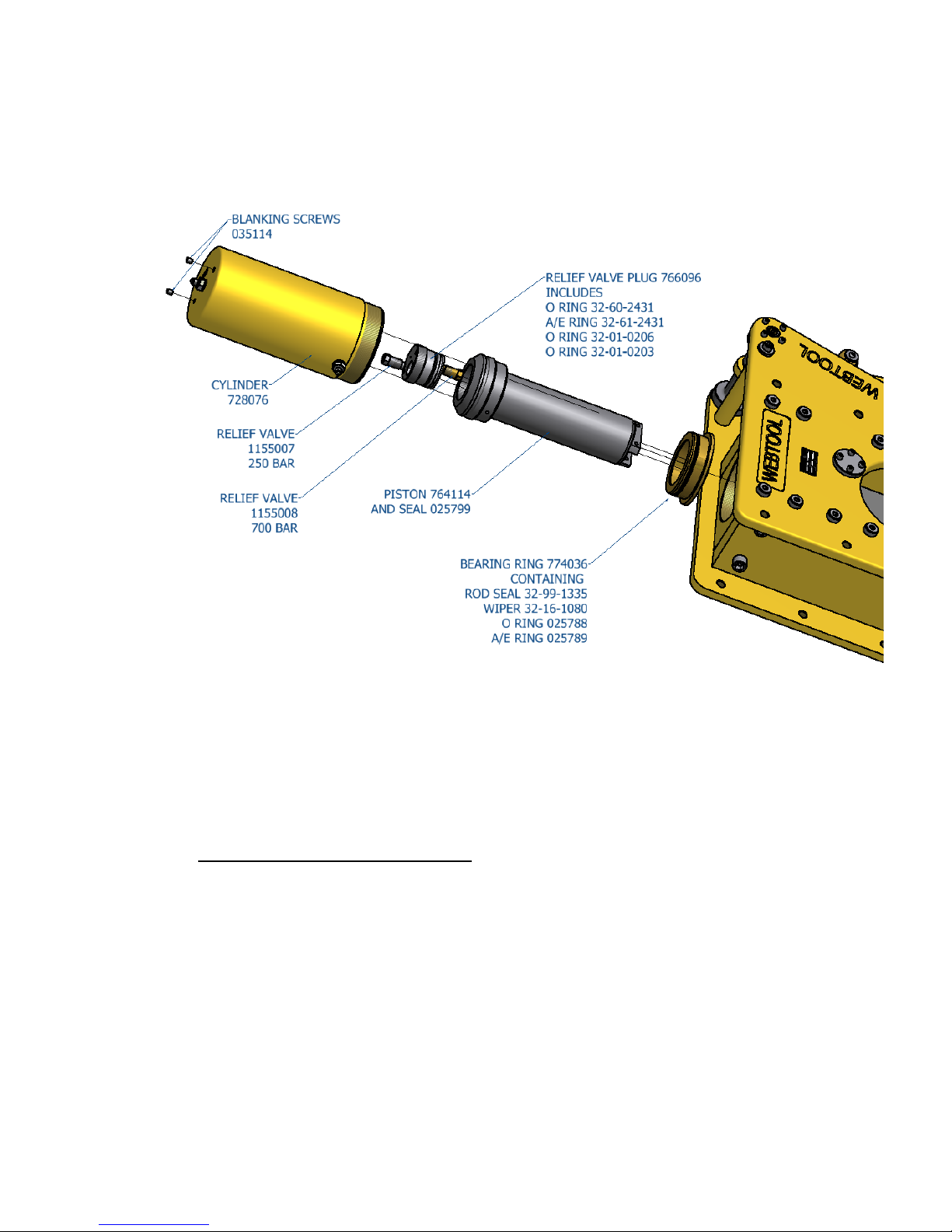
6. SERVICE
IMPORTANT –ENSURE THERE IS NO HYDRAULIC PRESSURE IN THE CYLINDER BEFORE
PERFORMING ANY SERVICE OR MAINTENANCE PROCEDURES ON THIS CUTTER
It is unlikely that service would be required on the hydraulic components of the tool under
normal circumstances, but a seal spares kit is available if required. The only parts that would
need intermittent replacement would be the anvil and blade, depending on the frequency of
use and materials being cut. These parts can be ordered up on the following spares reference
numbers, but in addition please quote the tool serial number.
HCV155 seal kit, cutter and auxiliaries Part Number 995285
Seal Kit auxiliary cylinder only Part Number 995122
Anvil Part Number SSC6489
Blade Part Number 705051c
Blade Retaining Pin Part Number 030636 2 off
We advise that any servicing should be carried out by an authorised distributor only.
If required, the tool can be returned to the manufacturer for servicing and testing.
If servicing is to be undertaken by the user, please see note on proof testing under
SAFETY (Section 1), and the following:-
All servicing operations should be carried out in a clean environment to prevent contamination
of the oil and mating components.
Care should be taken with all mating areas ie. threads and sealing faces, as any damage or
abrasive contamination could cause galling or seizing on re-assembly.

Page 7of 17
The cylinder is a pressure vessel and should not be drilled, machined, mutilated or damaged in
any way for mounting purposes or to assist in its removal for servicing, any warranty could be
invalidated by such actions. Also see section 9
The use of stilsons to remove the cylinder is not recommended as damage will occur.
7. REPLACEMENT OF THE ANVIL
Loosen the four screws 035079 and the set screw 035073. Attached a screw to the Pivot Pin
761265 and pull free.
The lever will now be free, lift it free from the anvil SSC6489
The anvil SSC6489 may now be removed from the body.
Re-assembly is the reverse of the above process.

Page 8of 17
8. REPLACEMENT OF THE CUTTING BLADE
First withdraw the anvil as described above.
Pump out the main ram until the blade retaining pins 030636 can be seen in the opening of the
cutter body.
Drift out the pins 030636 and slide the blade 705051C out of the tool.
Gloves may be worn to protect the hands when removing the blade from the tool
When refitting the new blade ensure the retaining pins are below the surface of the ram on
both sides.
9. REMOVAL OF THE MAIN CYLINDER
If it is necessary to renew the hydraulic seals, first remove the blade as described above in
section 8, the cylinder must then be removed from the tool. As an aid to this, remove the 2
blanking screws 035114, then a bar is to be fastened to the top of the cylinder using the 2
tapped holes, apply a torque and not a bending moment when unscrewing the cylinder. The

Page 9of 17
cylinder is a pressure vessel and should not be drilled, machined, mutilated or damaged in any
way for mounting purposes or to assist in its removal for servicing, any warranty could be
invalidated by such actions. Do not use Stilsons to remove the cylinder as damage will occur.
A cylinder assembly tool is available as an optional extra part number SK4377A
Removing the cylinder will expose the ram, bearing ring and relief valve plug and allow access to
all the seals, note the positions of the relief valves and ensure they are replaced in the correct
positions.
10. REMOVAL OF THE AUXILIARY CYLINDERS
First remove the hoses from the auxiliary cylinders. Free the lever as described in section 7,
remove the 4 cap screws 035079 and the mounting stud 079044, the cylinders are now free.
Remove the screw and washer from the cylinder rod pin, by pulling the lever away from the
body the cylinders will be free.

Page 10 of 17
11. REPLACING AUXILIARY CYLINDER SEALS
Remove the 4 screws 035067 to free the end cap SSC6476, remove the M4 set screw to allow
the piston block 709062 to be unscrewed, the piston can now be removed, all seals are now
accessible

Page 11 of 17
Cutter Seal Kit –including auxiliary cylinders
995285
Part No.
Description
Qty
025 799
Piston head seal
1
32-99-1335
Rod seal
1
025 789
Anti extrusion ring –cylinder/ram bearing ring
1
025 788
Piston seal –cylinder/ram bearing ring
1
32-16-1080
Wiper
1
025 801 *
Piston seal - Auxiliary cylinder
2
025 802 *
Rod seal –Auxiliary cylinder
2
025 569 *
Ram Wiper –Auxiliary cylinder
2
025 311 *
O Ring –Auxiliary cylinder
2
32-60-2431
O Ring –Relief valve plug
1
32-61-2431
A/E ring for 32-60-2431
1
32-01-0203
O Ring for 1155008
1
32-01-0206
O Ring for 1155007
1
Items marked thus * are in seal kit 995122 replacement seals for one auxiliary cylinder
HCV155 –Part List
980217
Part No.
Description
Qty.
982 130
Cutter body
1
728 076
Cylinder
1
764 114
Ram
1
774 036
Bearing ring
1
705 051c
Blade
1
766 100
Blanking plug
1
SSC6489
Anvil
1
030 636
Blade retaining pin
2
766 096
Relief valve plug
1
1155007
Relief valve 250 bar
1
1155008
Relief valve 700 bar
1
982 132
Auxiliary cylinder assembly
2
715 349
Anvil guide bush
1
715 351
Anvil bush
1
715 345
Pivot pin lever bush
2
761 247
Anvil sliding pin
1
749 044A
Pivot pin housing, left
1
749 044B
Pivot pin housing, right
1
761 265
Lever pivot pin
1
079 044
Auxiliary cylinder mounting stud
2
765 213
Lever
1
761 266
Cylinder rod pin, auxiliary cylinder
2
080 971
Washer
4
035 111
Socket cap screws M6 x 35
4
035 079
Socket cap screw M6 x 25
16
035 066
Socket cap screw M6 x 20
8
035 076
Socket button head screw M6 x 10
5

Page 12 of 17
035 073
Socket set screw M6 x 10
1
035 114
Socket set screw M8 x 10, cylinder blanking
2
766 095
Swival blanking cap JIC
2
752 342
Webtool nameplate
1
766 047
Plastic plug
4
791 157
Coupling , 7/16” JIC No.4 – ¼” BSP
2
752 573
Pressure warning label
1
Auxiliary Cylinder parts list (for 1 cylinder)
982132
Part No.
Description
Qty
709 062
Piston block
1
728 078
Lever cylinder
1
SSC 6476
End cap
1
764 116
Piston
1
026 701
Pellet
1
995 122
Seal kit auxiliary cylinder
1
043 206
Piston block screw
1
035 067
End cap screw
4
701 195
Adaptor
1
Completion Kit HCV155
999021
765 338
Manifold block
1
035 134
Intensifier captive screw
4
765 315
Intensifier captive plate
1
769 012
Connectors
2
035 150
Socket cap screws
2
725 005
Stainless steel intensifier
1
020 994
Lock nuts
4
766 086
Filter
2
32-07-0035
Bonded seals
10
32-67-1201
Bonded seals for intensifier
2
791 154
Male to male couplings ¼” BSP
8
791 159
Male to male couplings ¼” NPT to ¼” BSP
2
035 080
Blanking set screws
3
31-47-0310
Balls
3
1241059
Auxiliary hose
2
1241060
Auxiliary hose
2
1241058
Hose –cutting stroke 700 bar
1
1241057
Hose –return stroke 700 bar
1
025 932
A/E ring for seal 025674
2
025 674
O Ring
2
791 157
Male to male coupling ¼”BSP to No. 4 JIC
4

Page 13 of 17
This HCV155 cutter is compatible with the following optional extras, not supplied as standard.
Cylinder Assembly Tool - SK4377A
This tool can be used on RCV75, RCV75HD, RCV115, RCV135, RCV155, RCV190, HCV100,
HCV120, HCV250 and HCV270 cutting tools
Webtool Hydraulic Intensifier –HP690A (available in a range on intensification ratios)
For further information contact the manufacturer (Allspeeds Ltd) or an authorised distributor.

Page 14 of 17
OPTIONAL COMPLETION KIT 999021 FITTED TO HCV155
This is a special manifold block unique to the HCV155, fitted with intensifier and hoses, the
manifold has two connections for the blade movement on the side and two on the top for
activating the anvil in and out. All connections are clearly marked. if the intensifier is removed it
is important that it is replaced in exactly the same position, the manifold block is marked with
“R” and “IN” this corresponds with the same markings on the bottom of the intensifier.
The intensifier has 2 pins in the bottom, each has a seal, to replace the seals remove the 4 nuts
holding down the intensifier captive plate, remove the intensifier, the seals are now accessible.
Below is shown the cutter fitted with a completion kit, a side plate has been removed to show
more clearly the hose connections
The hoses connected to the main cylinder are rated at 700 bar, those for the auxiliary cylinders
are rated at 400 bar.
The couplings for the cutting stroke and return stroke are 7/16” JIC all other couplings in the
manifold block are ¼” BSP

Page 15 of 17
Below is shown a close up of the manifold block with hoses and connections removed for clarity,
all hydraulic connection points are clearly marked, if any hoses are removed it is very important
that they are replaced in the correct position.

Page 16 of 17
Below is a schematic drawing of the hydraulic system for the HCV155

Page 17 of 17
CUTTING EDGE TECHNOLOGY
Webtool specialises in engineering powerful hydraulic tools for
cutting and gripping rope, cable and umbilicals.
Models designed for use in subsea environments by ROV’s, and
surface applications in hostile environments.
Wire rope cutters (WCS and WCOS) –capable of cutting steel wire rope
up to 75mm diameter
Wire Rope Cutters (RCV) –capable of cutting steel wire rope up to
190mm diameter
Cable Cutters (HCV) –capable of cutting cable, umbilical and armoured
flexible pipe lines up to 330mm diameter
Softline Cutters (SL) –capable of cutting fibre ropes in various sizes
Wire Rope / Cable Grippers
Wire Rope Clamps
Automatic Shackles
Application specific solutions
Our in house design and manufacturing capability means we can
quickly and efficiently develop a solution to suit your particular
application. Contact our engineering department to discuss how we
can help.
Table of contents
Other Webtool Cutter manuals