Webtool HCV270 User manual

RISER/FLOWLINE/HOSE/UMBILICAL CUTTER HCV270
PRODUCT CODE No. 980216
INSTRUCTIONS FOR INSTALLATION,
OPERATION & MAINTENANCE
Revision 7 issue 6. Modification No. 20644 Date 17TH. Oct 2013
© Copyright Allspeeds Holdings Ltd.
This document must not be modified in any way.
Tel:
+44
(0)191 490 1547
Fax: +44 (0)191 477 5371
Email: northernsales@thorneandderrick.co.uk
Website: www.cablejoints.co.uk
www.thorneanderrick.co.uk

Page 2of 16
Description
The cutter is intended for use on Coflexip type riser and will cut hose up to 270mm diameter. It
may be used on alternative materials, such as electrical power or communication cables, up to a
maximum of 200mm diameter. Where small diameters are to be cut, effort should be made to
place the material centrally along the anvil to minimise any offset loading. The cutter is not
designed to cut large diameter wire rope.
IMPORTANT
If it is required to extend the recommended use of the cutter, for instance to cut solid steel bar
or wire rope, please refer to the manufacturer with full details of material size and tensile
strength. Cutting unsuitable materials could result in damage to the tool.
1. SAFETY
Before operation, read and understand this operations manual.
Whilst the tool is intended for remote or local operation sub-sea, there is no reason why it
should not be used above surface.
Ensure that the tool, hoses and pump are in good condition and properly connected.
Ensure that suitable pressure regulation equipment is used and that the unit is not subjected to
pressures higher than those stated in section 3
In all cases, where an operator is present, the safety aspects must be reviewed before the
cutting operation is commenced.
No attempt should be made to cut any material that is under tension.
Ensure that the operator is shielded from the cutting blade during the cutting operation.
When cutting near the very end of hose fragments can be expelled from the tool, please ensure
that the operator is shielded from these.
If in doubt please contact the manufacturer (Allspeeds Ltd) or an authorized distributor for
assistance.
If at any time it is necessary to carry out proof tests on the tool, e.g. after service on the
hydraulic cylinders, it must be returned to the supplier for testing where the following
procedures apply.
The maximum proof test pressure should not exceed 125% of the maximum working pressure
and this should only be done by Allspeeds using our specially adapted test rig.
The tool should be guarded during the proof test operation, and be carried out in
a safe working environment.
The proof pressure should be applied gradually, until the maximum pressure is reached.

Page 3of 16
Important: Please note this tool is designed for intermittent subsea use. Please refer to the
manufacturer (Allspeeds Ltd) or an authorized distributor should you wish to use this tool
subsea for any period over 14 days.
CAUTION –Any modification made to this tool will invalidate the warranty and may lead to
equipment failure or personal injury. If in doubt please contact the manufacturer (Allspeeds Ltd)
or an authorised distributor for assistance.
INSPECT THE TOOL BEFORE USE
With the cutter isolated from the hydraulic supply, check the condition of the blade edge. If the
blade is damaged or blunt replace with a fresh blade before cutting. This procedure is as
described in section 8.
Ensure that care is taken when checking the blade as the edge may be sharp
Check the condition of the anvil. It is normal that the anvil will show an indent where the blade
has pressed down into it and can withstand multiple cuts, but any excessively damaged anvil
should be replaced. This procedure is as described in section 7
CAUTION –USE OF BLADES AND PARTS NOT APPROVED BY WEBTOOL MAY RESULT IN TOOL
FAILURE AND CONSEQUENTIAL DAMAGE
2. CUTTING CAPACITY
The cutter is intended for use on Coflexip type riser and will cut hose up to 270mm diameter. It
may be used on alternative materials, such as electrical power or communication cables, up to a
maximum of 200mm diameter. Where small diameters are to be cut, effort should be made to
place the material centrally along the anvil to minimise any offset loading. The cutter is not
designed to cut large diameter wire rope.
3. INSTALLATION
Tapped Holes, ⅝” UNC, are provided in the tool body (see sketch) which can be
used for any attachment necessary to mount the cutter. The cylinder is a pressure vessel and is
not recommended as a mounting point, the cylinder should not be drilled, machined, mutilated
or damaged in any way, any warranty could be invalidated by such actions.

Page 4of 16
Two hydraulic supplies are required, ported as shown below. The maximum
working pressures are shown in the table below and pressure limiting valves must be fitted into
the supply to limit the pressures to these levels.
The weight of the tool is 352kg.
TABLE 1.
Function
Max. Working Pressure
Swept Volume
Port Tapping
psi
bar
ml.
U.S. Gallon
Main Ram Working Stroke
10,000
690
5300
(1.40)
⅜” NPT
Main Ram Return
Stroke
10,000*
690*
1910
(0.51)
⅜” NPT
Auxiliary Cylinders Out
Stroke
(to retract anvil)
2,750
190
132
(0.035)
¼” NPT
Auxiliary Cylinders Instroke
(to reset anvil)
2,750
190
81
(0.021)
¼” NPT
*N.B. Actual pressure required to return Ram < 200 psi (14 bar)

Page 5of 16
4. OPERATION
Before deployment, function test the tool and ensure that all operators are familiar with
this procedure. ROV observation of the tool should be maintained at all time during operation.
Prior to use, ensure no damage has occurred to the blade or anvil. Ensure the anvil is
fully retracted.
DEPLOYMENT -
Prior to use, the auxiliary cylinder outstroke should be operated to withdraw the anvil.
This clears access for the cutter to be placed over the hose.
Place the cutter over the hose. Ensure that the hose is as far into the cutter as possible so
that the anvil does not foul as it is reset.
Place the cutter over the hose. Ensure that the wire rope is as far into the cutter as possible.

Page 6of 16
Operate the auxiliary cylinder instroke to position the anvil fully home under the hose, the
main ram should not be activated until the auxiliary cylinders are operated to the full extent
of their stroke.
Operate the main ram down-stroke to sever the hose. Once the hose is severed, pressurize the
main ram retract port to withdraw the cutting blade. Then, and only then, retract the anvil. It is
important not to operate the anvil cylinder whilst the main ram and blade are in the fully
extended position.
If a further cut is required, the above procedure should be repeated.

Page 7of 16
N.B. Do not operate the auxiliary cylinders when the main ram is fully extended since this would
damage the anvil.
Please note that this tool has a relief valve fitted which will blow off at approx. 750 bar, DO NOT
leave the pressure on so that the relief valve is continually blowing off.
TROUBLESHOOTING
If the hose does not cut through completely on the first attempt, cycle the blade by retracting it
slightly and then attempting the cut again.
If the hose does not completely cut after multiple cycles of the blade, check the input pressure
to the main input of the cylinder. This can be a maximum of 700 bar (10,000psi).
If the rope to be cut is still not severed after multiple cycles and at a pressure of 700 bar, retract
the blade and then the anvil and return the tool to the surface for inspection of the blade and
anvil, replace if necessary.
IMPORTANT NOTE –ENSURE THAT THE BLADE IS FULLY RETRACTED AND THAT ALL PRESSURE
TO THE CUTTER IS RELIEVED AS IT IS RAISED TO THE SURFACE. FAILURE TO DO THIS CAN LEAD
TO A DANGEROUS BUILD UP OF PRESSURE IN THE CYLINDER.
5. AFTER USE
When the tool is retrieved, it should be hosed off with clean water, allowed to drain and
sprayed externally with a de-watering fluid. Before storage, inspect the general condition of the
tool. Particular attention should be paid to the anvil and blade. The anvil should be clean and
free from any damage or bruising on the outside diameter that would prevent it from retracting
properly. The blade edge should be smooth and free from any serrations. Note that a slight
ripple to the blade edge is acceptable and will not cause problems. Any minor damage can be
smoothed off with an oil stone if necessary.
IMPORTANT: Please note this tool is designed for intermittent subsea use. Please refer to the
manufacturer should you wish to use this tool subsea for any period over 14 days.
6. SERVICE
It is unlikely that service would be required on the hydraulic components of the tool under
normal circumstances, but a seal spares kit is available if required. The only parts that would
need intermittent replacement would be the anvil and blade depending on the frequency of use
and materials being cut. These parts can be ordered up on the following spares reference
numbers, but in addition please quote the tool serial number.
Seal Kit Part Number 995 288
Anvil Part Number SSC 6488
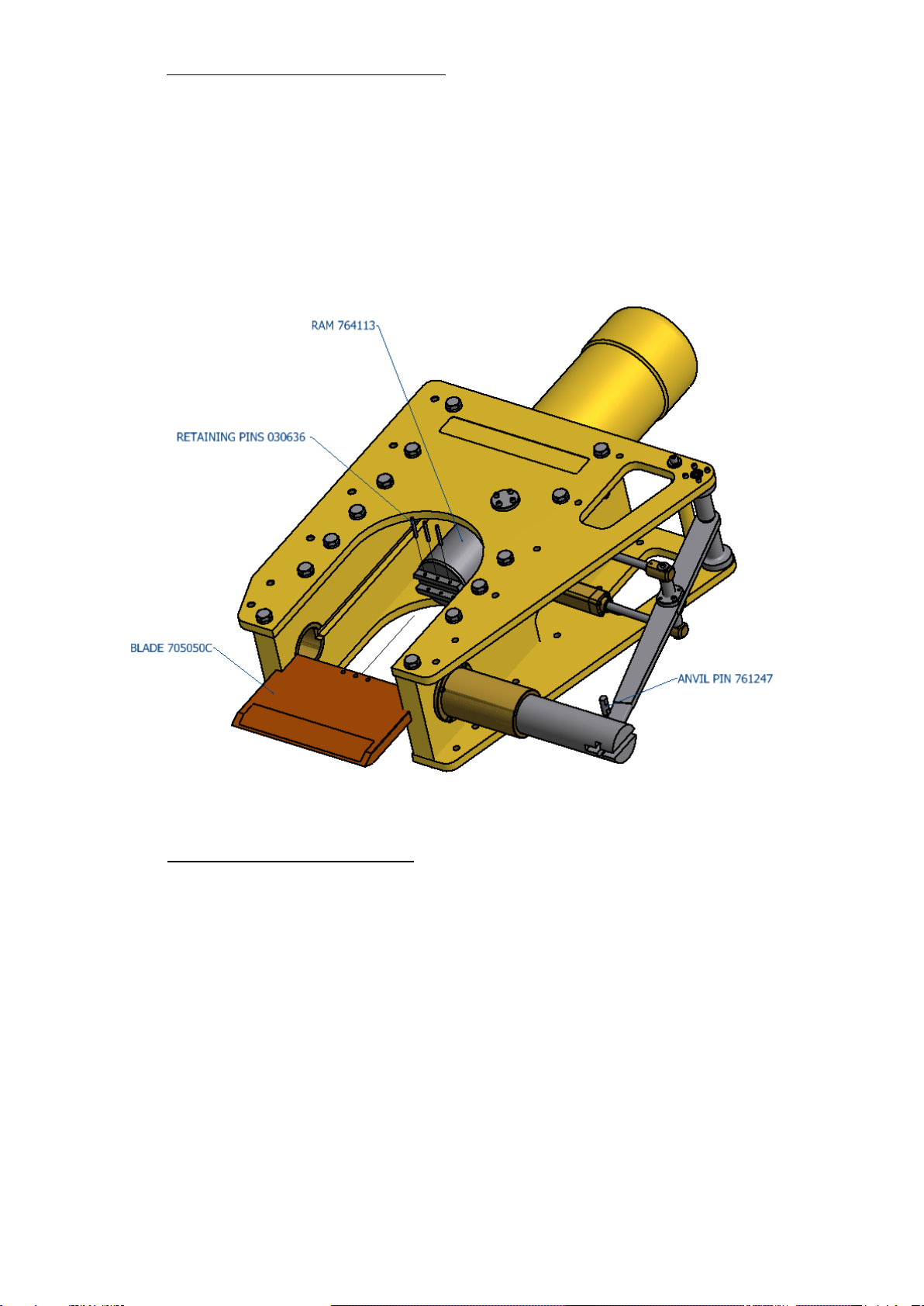
Blade Part Number 705 050C
We advise that any servicing should be carried out by an authorised distributor only.
If required, the tool can be returned to the manufacturer for servicing and testing.

Page 8of 16
If servicing is to be undertaken by the user, please see note on proof testing under
SAFETY (Chapter 1), and the following:-
All servicing operations should be carried out in a clean environment to prevent contamination
of the oil and mating components.
Care should be taken with all mating areas ie. threads and sealing faces, as any damage or
abrasive contamination could cause galling or seizing on re-assembly.
The cylinder is a pressure vessel and should not be drilled, machined, mutilated or damaged in
any way for mounting purposes or to assist in its removal for servicing, any warranty could be
invalidated by such actions.
The use of stilsons to remove the cylinder is not recommended as damage will occur.
7. REPLACEMENT OF THE ANVIL
Extend the auxiliary cylinders so that the lever arm 765212 exits the guide bush 715348.
Loosen the 8 off M6 screws 035079 holding pivot pin housings 749045A & B.
Loosen the M6 retaining screw 035073.
Withdraw the pivot pin 761267 far enough to release the lever arm. (There is an M6 tapped
hole in the end of the pivot pin to assist in withdrawing this)
The lever arm can be moved upwards to separate it, and the anvil pin 761247, from the anvil
SSC6488. The anvil may now be slid out from the guide bush. Re-assembly is the reverse of the
above process.

Page 9of 16
8. REPLACEMENT OF THE CUTTING BLADE
First withdraw the anvil as described above.
Pump out the main ram until the blade retaining pins 030636 can be seen in the opening of the
cutter body.
The three pins are ¼” (6.35mm) diameter and they should be knocked out enough to release the
blade.
9. REMOVAL OF THE MAIN CYLINDER
If it is necessary to renew the hydraulic seals, the cylinder must be removed from the tool. As an
aid to this, 2 off tapped holes are provided in the cylinder end face. These are M10 x12 deep on
130mm centres.
First, remove the anvil as described above, pump out the ram and remove the blade.
To use the holes in the top of the cylinder first remove the coupling, then the blanking screws
035050 and fasten a piece of flat bar, typically 30x10mm section and 900mm long centrally to
the top of the cylinder. This can be used to loosen or re-tighten the cylinder. Do not use Stilsons
to remove the cylinder as damage will occur.
Unscrew the cylinder 728075 and remove from the assembly, it will come free but still attached
will be the ram 764113 and bearing ring 774032.

Page 10 of 16
Put the assembled parts into a plastic dust bin or similar vessel, fit the coupling to the top of the
cylinder, attach a hand pump to the coupling and pump out the ram, importantly, by hand.
The ram can now be removed from the bearing ring and all seals will be accessible.
The ram has been fitted with a relief valve plug, this also contains seals, to remove the part the
two M8 tapped holes can be used to unscrew the plug, the two relief valves have been careful
set to blow off at a set pressure, these can be removed with a 17mm socket and 5mm allen key,
care should be taken not to disturb the settings.
When re assembling the relief valve plug with the ram, first fill the ram with oil to the bottom of
the counterbore, smear silver goop on to the threads of the plug, screw in the plug, remove the
set screw and ball in the top of the plug and top up the inside of the ram with oil until it fills the
screw hole, fit the ball and screw and lock tight.
Check that the plug and the relief valves are tight and below the top face of the ram.
Fit the ram into the bearing ring, place the cylinder upside down under a press, position the ram
on top of the cylinder and push home.
Position the assembly on top of the cutter, put grease on the threads and screw in the cylinder
using the two tapped holes and the flat bar, remove the bar, replace the screws and fit the
couplings.

Page 11 of 16
HCV 270 –Part List
980216
Part No.
Description
Qty.
728075
Cylinder
1
764113
Ram
1
774032
Bearing ring, main ram
1
SSC6488
Anvil
1
715348
Bush, anvil guide
1
715350
Bush, anvil
1
715345
Bush, lever, pivot pin
2
761247
Pin, sliding, anvil
1
749045A
Pivot pin housing, left hand
1
749045B
pivot pin housing, right hand
1
761267
Pin, pivot, lever
1
079043
Mounting stud, auxiliary cylinder
2
765212
Lever
1
761249
Cylinder rod pin, auxiliary cylinder
2
080971
Washer, special, M6
4
31-99-2809
Eye bolt, 5/8” UNC thread
2
705050C
Blade
1
766093
Relief valve plug
1
035080
Socket set screw
1
31-47-0310
Ball for relief valve plug
1
32-99-1131*
Seal, piston head*
1
32-99-1333*
Seal, rod*
1
32-60-5725*
Seal, ‘O’ ring, cylinder/ram bearing, upper*
1
32-61-5725*
AE ring, cylinder/ram bearing, upper*
1
32-60-5727*
Seal ‘O’ ring, cylinder/ram bearing, lower*
1
32-61-5727*
AE ring, cylinder/ram bearing, lower*
1
025568*
Wiper, rod*
1
32-60-3023*
O ring
2
32-61-3023*
AE ring for 32-60-3023
2
32-60-2419*
O ring
1
32-61-2419*
AE ring for 32-60-2419
1
32-01-0206*
O ring
1
035111
Screw, sock cap. M6 x 35
4
035079
Screw, sock cap, M6 x 25
16
035066
Screw, sock cap, M6 x 20
8
035076
Screw, sock button head M6 x 16
5
035073
Screw, sock set, M6 x 10
1
035080
Screw, sock set, M10 x 12, cylinder blanking
2
33-99-1163
Screw, taper pressure plug, ⅜ NPTF
1
030636
Pin, blade retaining
3
752342
Nameplate
1
752571
Cutting stroke label
1
752573
Pressure warning label
1
766047
Plug, blanking, ¼” BSP, red polythene
4
766061
Plug, blanking, ⅜” BSP, red polythene
2
982129
Body sub-assembly
1
982131
Auxiliary cylinder sub assembly (see separate parts list)
2
1155006
Relief valve 700 bar
1
1155007
Relief valve 250 bar
1
* These parts are in the seal kit along with the auxiliary seals in seal kit 995288

Page 12 of 16
Auxiliary Cylinder, Sub-Assembly –Part List
982 131
Part No.
Description
Qty.
709062
Piston block
1
728077
Cylinder
1
SSC6476
End cap
1
764115
Piston
1
026701
Pellet, aluminium, 3Ø
1
025311**
Seal, ‘O’ ring, end cap**
1
025569**
Scraper, rod**
1
025801**
Seal, piston**
1
025802**
Seal, rod**
1
043206
Screw, socket set, M4 x 6, piston block
1
035067
Screw, sock cap, M5 x 30, end caps
4
701195
Adaptor, 90º, ¼ NPT male / ¼ NPT female
1
** These parts are in the auxiliary seal kit 995122 and also in full seal kit 995288
This HCV270 cutter is compatible with the following optional extras, not supplied as standard.
Cylinder Assembly Tool - SK4377A
This tool can be used on RCV75, RCV75HD, RCV115, RCV135, RCV155, RCV190, HCV100,
HCV120, HCV250 and HCV270 cutting tools

Page 13 of 16
Webtool Hydraulic Intensifier –HP690A (available in a range on intensification ratios)
For further information contact the manufacturer (Allspeeds Ltd) or an authorised distributor.
Optional Completion kit 999018 Fitted to HCV270 including Manifold, Intensifier and Hoses
This cutter is also available fitted with a completion kit, which includes manifold block,
intensifier and hoses, the part number for this tool is 999018

Page 14 of 16
The manifold block is secured in position using the two socket cap screws on the anvil lever side
of the cutter
The manifold block is fitted with intensifier and hoses, if the intensifier is removed it is
important that it is replaced in exactly the same position. The hose connected to the ‘BLADE
DOWN’ port must be connected to the Intensifier port marked ‘IN’ and the hose connected to
the ‘BLADE UP’ to the Intensifier ‘R’ port.
Below is shown the cutter with a side plate removed to show the hose arrangement
The two hoses connected to the far ports on the underside of the auxiliary cylinders, are both
connected to the underside of the ‘ANVIL OPEN’ port, the two other hoses connected to the
front of the auxiliary cylinders connect to the underside of the ‘ANVIL CLOSED’ port.

Page 15 of 16
Below is shown the schematic drawing of the hydraulic system for the HCV270
HCV270 Completion Kit –Part List
999 018
SK4372
Manifold block
1
725005
Intensifier
1
1242046
Adaptor ¼” BSP male both ends, straight
10
1242005
Adaptor ¼” BSP to ¼” NPT male both ends, straight
4
791123
Quick connector male end
4
726356
Male ¼” BSP connector for 791123
4
32-07-0035
Bonded seal ¼” BSP
15
1242061
Adaptor ¼” BSP to 3/8” NPT male both ends, straight
1
1242059
Hydraulic fitting 90º
1
1242060
Connector, high pressure
1
1242007
Hydraulic hose 700 bar
1
1241046
Hydraulic hose 225 bar
1
1241047
Hydraulic hose 225 bar
2
1241048
Hydraulic hose 225 bar
1
1241049
Hydraulic hose 225 bar
2
1241030
Hydraulic hose 225 bar
1
33-99-1160
Pressure plug
3

Page 16 of 16
CUTTING EDGE TECHNOLOGY
Webtool specialises in engineering powerful hydraulic tools for
cutting and gripping rope, cable and umbilicals.
Models designed for use in subsea environments by ROV’s, and
surface applications in hostile environments.
Wire rope cutters (WCS and WCOS) –capable of cutting steel wire rope
up to 75mm diameter
Wire Rope Cutters (RCV) –capable of cutting steel wire rope up to
190mm diameter
Cable Cutters (HCV) –capable of cutting cable, umbilical and armoured
flexible pipe lines up to 330mm diameter
Softline Cutters (SL) –capable of cutting fibre ropes in various sizes
Wire Rope / Cable Grippers
Wire Rope Clamps
Automatic Shackles
Application specific solutions
Our in house design and manufacturing capability means we can
quickly and efficiently develop a solution to suit your particular
application. Contact our engineering department to discuss how we
can help.
Tel:
+44
(0)191 490 1547
Fax: +44 (0)191 477 5371
Email: northernsales@thorneandderrick.co.uk
Website: www.cablejoints.co.uk
www.thorneanderrick.co.uk
This manual suits for next models
1
Table of contents
Other Webtool Cutter manuals