Webtool RCV190 User manual

Instruction Manual
for
Allspeeds Ltd.
Royal Works, Atlas Street
Clayton Le Moors, Lancashire, UK.
BB5 5LW
RCV190
Allspeeds Product Code 980230
Allspeeds Document Revision 6 issue 3
Date: 14/09/2023
Original instructions

980230 –RCV190 Manual Page 2 of 25
Rev 6 Issue 3. Date: 18/09/23
Table of Contents
1Important Notice –Read Before Use................................................................................... 3
2Introduction....................................................................................................................... 3
3Technical Data.................................................................................................................... 4
3.1 Physical......................................................................................................................................... 4
3.2 Hydraulic Requirements............................................................................................................... 4
3.3 Environmental Considerations ..................................................................................................... 4
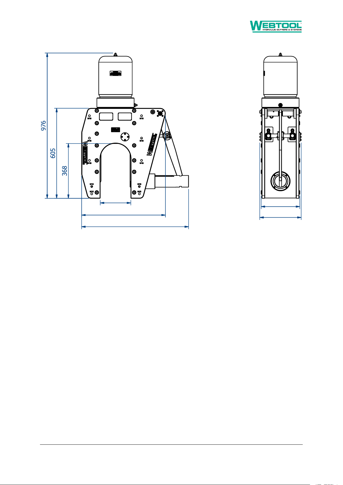
3.4 Dimensions................................................................................................................................... 5
4Declaration of Incorporation............................................................................................... 6
5General Safety Rules .......................................................................................................... 7
5.1 Warnings....................................................................................................................................... 7
5.2 Important Information ................................................................................................................. 7
5.3 Safety for Operation..................................................................................................................... 7
5.4 Safety for Maintenance................................................................................................................ 8
5.5 Warning Symbols.......................................................................................................................... 8
6Installation......................................................................................................................... 9
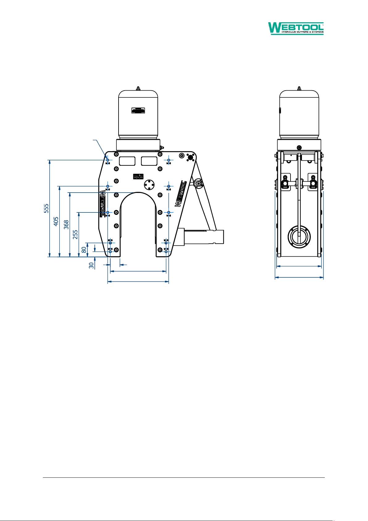
6.1 Mounting Holes............................................................................................................................ 9
7Hydraulic Connections...................................................................................................... 10
8Operating Instructions...................................................................................................... 11
8.1 Before Use.................................................................................................................................. 11
8.2 Deploying the Tool ..................................................................................................................... 11
8.3 Pre-Cut Check............................................................................................................................. 12
8.4 Extend the Blade (Cut Cycle) ...................................................................................................... 12
8.5 Retract the Blade (Return Cycle) ................................................................................................ 12
9Maintenance.................................................................................................................... 13
9.1 Maintenance Notes.................................................................................................................... 13
9.2 Maintenance Schedule............................................................................................................... 13
9.3 Remove & Replace Anvil............................................................................................................. 14
9.4 Remove & Replace Blade............................................................................................................ 17
9.5 Seal Detail................................................................................................................................... 19
10 Parts List.......................................................................................................................... 22
11 Decommissioning............................................................................................................. 23

980230 –RCV190 Manual Page 3 of 25
Rev 6 Issue 3. Date: 18/09/23
1Important Notice –Read Before Use
2Introduction
This manual covers the installation, operation and maintenance of a RCV190 as Allspeeds part
number 980230.
This is a double acting, hydraulically operated tool suitable for cutting steel wire rope and alternative
materials, such as electrical power or communication cables up to 190mm (7.5”) in diameter. It
requires two separate dual line hydraulic supply (feed and return) for the main cutter activation and
the hydraulically operated anvil.
Do not operate the blade unless the anvil is fully closed.
Ensure that the auxiliary cylinders are pressurised (200 bar)
to keep the anvil closed throughout the cut cycle.
Read, understand and follow the instructions within the
operating manual before deploying or operating the RCV190 cutter.
Failing to follow the instructions and operating the cutter with a
partially closed anvil will result in serious damage to the RCV190.
IF IN DOUBT, ASK!
See section 8 for more details

980230 –RCV190 Manual Page 4 of 25
Rev 6 Issue 3. Date: 18/09/23
3Technical Data
RCV190 (part number 980230)
3.1 Physical
Weight of RCV190 in air 296 kg (excluding hydraulic fluid and hoses)
Weight of RCV190 in water 257 kg (excluding hydraulic fluid and hoses)
Overall Dimensions 560mm (718mm) x 280mm x 976mm
3.2 Hydraulic Requirements
3.2.1 Main Cutter Cylinder
Cylinder Type Double acting (feed and return ports)
Maximum Operating Pressure 690 Bar (10,000 PSI)
Swept Volume Cut Stroke 5.2 Litre
Swept Volume Return Stroke 1.4 Litre
3.2.2 Anvil Auxiliary Cylinders
Cylinder Type Double acting (feed and return ports)
Maximum Operating Pressure 210 Bar (3,000 PSI)
Swept Volume Anvil In 0.08 Litre
Swept Volume Anvil Out 0.06 Litre
IMPORTANT –The maximum operating pressure stated above should not be exceeded during use of
this tool. Ensure that all fittings and hoses used are suitable for use at this pressure and rated
accordingly.
This RCV190 is compatible with the following hydraulic fluids:
Good quality hydraulic oil (e.g. Shell Tellus 32, 68 or similar)
Water glycol (e.g. Castrol Transaqua HT2).
Please note that whilst compatible, the use of water glycol fluids may reduce system life.
Ensure that the fluid used is cleaned to NAS Class 6 or better.
3.3 Environmental Considerations
This cutter should not be operated outside of the recommended temperature range of -5°C to +60°C.
This cutter is suitable for use subsea but should be regularly checked, cleaned and dewatered using a
suitable dewatering spray.

980230 –RCV190 Manual Page 5 of 25
Rev 6 Issue 3. Date: 18/09/23
3.4 Dimensions
Figure 1 –Overall dimensions

980230 –RCV190 Manual Page 6 of 25
Rev 6 Issue 3. Date: 18/09/23
4Declaration of Incorporation
DECLARATION OF INCORPORATION
Company name:
Allspeeds Ltd
Company address:
Royal Works, Atlas Street, Clayton le Moors, Accrington, Lancashire
BB55LW, UK
Machinery covered by this
declaration:
Description:
Hydraulic Cutting Tool
Model:
RCV190
Type:
980230
Serial No.:
The machinery conforms to the following essential requirements
of the Machinery Directive 2006/42/EC:
The machinery also conforms to
the following Directives:
N/A
The following standards have
been applied:
N/A
This machinery must not be put into service until the machinery into which it is to be incorporated
has been declared in conformity with the provisions of the machinery directive
The technical documentation is compiled in accordance with part A of
Annex VII of the Machinery Directive 2006/42/EC
Person authorised to compile the
relevant technical documentation
(based in the European
Community):
Name:
Chris Bond
Address:
Royal Works, Atlas Street, Clayton le Moors,
Accrington, Lancashire BB55LW, UK
The relevant authorised person undertakes to transmit, in response to a reasoned request by the national
authorities, relevant information on the machinery. This information will be transmitted by: (email, post)
Person authorised to make this
declaration:
Name:
Rory McGarry
Position in
company:
Technical Director
Signature :
Place of
Declaration:
Accrington, Lancashire, UK
Date of
Declaration:
16/12/20

980230 –RCV190 Manual Page 7 of 25
Rev 6 Issue 3. Date: 18/09/23
5General Safety Rules
5.1 Warnings
These warning are provided to improve safety and should be carefully read before installing, using or
maintaining the equipment.
5.2 Important Information
It is vital that these instructions are available to the equipment users. It is also important that they
are retained with the equipment if it is sold or transferred to another user.
5.3 Safety for Operation
IMPORTANT - This is an inherently dangerous piece of cutting equipment and is supplied without
guarding. It is vital that the installer and end user perform a risk assessment and implement any
safety features that they deem necessary and enforce a safe system of work before use.
To prevent the risk of injury, the cutter should only be used by fully trained and competent
operators.
•Make sure that all safety devices are in place and functioning correctly
•Make sure the working area is free of any obstructions
•Check that all hydraulic hoses are in good condition
•Ensure that all operators are clear of the area before cutting commences
Recommended PPE for operation and maintenance includes safety shoes, safety glasses, ear
defenders and gloves.
IMPORTANT - If the item being cut is under tension there is the risk of it recoiling when severed.
Ensure that all operators are out of the immediate area before operation.
Any spilt oil or trailing hoses may create a slipping or tripping hazard. Care must be taken around the
work area. Energised hoses may move about during operation and should be fitted with whip-check
devices to contain them in case of a burst.

980230 –RCV190 Manual Page 8 of 25
Rev 6 Issue 3. Date: 18/09/23
5.4 Safety for Maintenance
Repairs carried out by untrained or unauthorised personnel may result in personal injury or serious
malfunction of the tool.
Ensure that the cutter is isolated from and free of hydraulic pressure before any maintenance is
carried out.
5.5 Warning Symbols
General hazard. Hydraulic cutting tool with inherently
dangerous moving parts. Please read and understand this
manual to avoid the risk of injury.
Cut or severing hazard due to the cutting blade.

980230 –RCV190 Manual Page 9 of 25
Rev 6 Issue 3. Date: 18/09/23
6Installation
6.1 Mounting Holes
The cutter body contains a number of mounting holes, as shown on the drawing below:
Figure 2 –Mounting holes
Ensure that the tool is securely mounted at multiple points and that mounting method is robust
enough to support the tool. Consult tool mass in section 3.1 when considering mounting possibilities.

980230 –RCV190 Manual Page 10 of 25
Rev 6 Issue 3. Date: 18/09/23
7Hydraulic Connections
Figure 3 –Hydraulic ports
It is the responsibility of the end user to ensure that a suitable hydraulic supply is installed. It is
recommended that a relief valve should also be incorporated in the return line to prevent excessively
high pressures in the annular side of the hydraulic cylinders should the return to tank become
blocked for any reason.

980230 –RCV190 Manual Page 11 of 25
Rev 6 Issue 3. Date: 18/09/23
8Operating Instructions
8.1 Before Use
With the hydraulic supply isolated, check the following parts of the cutter:
Item
Procedure
Check the condition of the anvil
As described in section 9.3
Check the condition of the blade
As described in section 9.4
Before use of the tool, ensure that all operators are at a safe distance from the cutter, and that any
guarding or safety features are installed and operational.
Check that the hydraulic supply is set to an appropriate level for operation as stated in section 3.2.
8.2 Deploying the Tool
Begin the operation with the anvil fully retracted. To achieve this, pressurise the ‘Anvil Out’ port on
the RCV190.
Place the cutter over the workpiece. Ensure that the workpiece is fully inserted into the mouth of the
tool so that there is no risk of the anvil fouling against it as it is closed.
Close the anvil over the workpiece by pressurising the ‘Anvil In’ port on the RCV190. Ensure that the
‘Anvil Out’ port is open to tank.
Fully inspect the tool to ensure the anvil is fully closed before continuing.
Figure 4 –Rope position

980230 –RCV190 Manual Page 12 of 25
Rev 6 Issue 3. Date: 18/09/23
8.3 Pre-Cut Check
IMPORTANT - Ensure that the anvil is fully closed before
performing a cutting operation.
IMPORTANT - Maintain pressure on the auxiliary anvil instroke to
keep the anvil closed throughout the cut cycle.
DO NOT OPERATE THE MAIN RAM IF THE ANVIL IS NOT FULLY
CLOSED AND PRESSURISED
8.4 Extend the Blade (Cut Cycle)
To extend the blade, pressurise the ‘Blade Down’ port on the RCV190 whilst ensuring that the ‘Blade
Up’ port is open to tank. Do not exceed the maximum operating pressure. Continue to apply pressure
until the cut is complete.
IMPORTANT –Do not attempt to open the anvil without first retracting the main
ram.
8.5 Retract the Blade (Return Cycle)
To retract the blade, pressurise the ‘Blade Up’ port on RCV190 whilst ensuring that the ‘Blade Down’
port is open to tank. Do not exceed the maximum operating pressure.

980230 –RCV190 Manual Page 13 of 25
Rev 6 Issue 3. Date: 18/09/23
9Maintenance
It is unlikely that service would be required on the hydraulic piston of the tool under normal
circumstances, but a seal spares kit is available (995133) and it is recommended to stock this at all
times.
The only parts that would need intermittent replacement would be the anvil and blade depending on
the frequency of use, materials being cut and the corrosive conditions present during operation.
IMPORTANT - Replacement parts must always be sourced from Allspeeds Ltd. The use of unofficial
components will invalidate the warranty and may lead to tool damage or system failure.
9.1 Maintenance Notes
IMPORTANT –This cutter should only be serviced by qualified personnel. If in any doubt please
contact Allspeeds Ltd or a distributor.
Most maintenance task can be carried out with standard tools.
All servicing operations should be carried out in a clean environment to prevent contamination of the
oil and mating components.
Care should be taken with all mating areas, including threads and sealing faces, as any damage or
abrasive contamination could cause galling or seizing on re-assembly. Please note a suitable anti-
galling paste should be used (we recommend Swagelok Silver Goop) on all stainless steel threads.
The cylinder (728090) is a pressure vessel and should not be drilled, machined, mutilated or damaged
in any way for mounting purposes or to assist in its removal for servicing, any warranty could be
invalidated by such actions.
The use of a Stilson wrench to remove the cylinder is not recommended as damage will occur.
Before carrying out any maintenance tasks ensure that the equipment is fully isolated and that there
is no residual pressure in the system.
9.2 Maintenance Schedule
This tool requires the following operations or service tasks to be completed as listed:
Task
See section
Frequency
Visual inspection of blade and anvil
9.3, 9.4
14 days or after cut, whichever is soonest.
Function test (extend and retract ram)
8.4, 8.5
14 days if unused
Clean and dewater
7 days
Replace blade
9.4
As required
Replace anvil
9.3
As required
Replace seals
9.5
12 months
Table 1 –Maintenance schedule

980230 –RCV190 Manual Page 14 of 25
Rev 6 Issue 3. Date: 18/09/23
9.3 Remove & Replace Anvil
IMPORTANT –The anvil may have sharp edges and imbedded material left behind from cutting
operations. Wear suitable gloves when handling the anvil.
IMPORTANT –Ensure that the hydraulic supply is isolated before proceeding.
IMPORTANT - Replacement parts must always be sourced from Allspeeds Ltd. The use of unofficial
components will invalidate the warranty and may lead to tool damage or system failure.
The anvil will show an indent where the blade contacts it during a cut, but can be reused. Any
excessively damaged or worn anvil should be replaced as described below.
Ensure that the blade is retracted before removing the anvil. This is as described in section 8.5.
With the anvil open or closed, remove one off screw (035076) and then remove reaction pin
(761267). The anvil arm should now be free to move vertically.
Figure 5 –Anvil removal step 1

980230 –RCV190 Manual Page 15 of 25
Rev 6 Issue 3. Date: 18/09/23
Figure 6 –Anvil removal step 2

980230 –RCV190 Manual Page 16 of 25
Rev 6 Issue 3. Date: 18/09/23
IMPORTANT –Mass of anvil (SSC6500) is 14.7kg. Ensure a safe system of work at all times.
Slide the anvil (SSC6500) out of the cutter.
Figure 7 –Anvil removal step 3
Anvil replacement is the reverse of the disassembly procedure.

980230 –RCV190 Manual Page 17 of 25
Rev 6 Issue 3. Date: 18/09/23
9.4 Remove & Replace Blade
IMPORTANT - The cutting edge may be sharp following tool operation, extreme caution and care
should be taken when checking it. Wear suitable gloves when handling the blade.
IMPORTANT - Ensure that the hydraulic supply is isolated before proceeding.
IMPORTANT - Replacement parts must always be sourced from Allspeeds Ltd. The use of unofficial
components will invalidate the warranty and may lead to tool damage or system failure.
The blade edge should be regularly checked to ensure that it is in good condition. This would be a
consistent blade edge with no chips or deformations noted along the entire cutting edge.
For safety we recommend that this operation is performed with the tool led down.
Begin the anvil pumped out to its full extent or with it fully removed as described in section 9.3. The
Main ram should be in the fully extended position.
Remove the 3 off blade pins (030636). If the blade is fully extended then the pins should be clearly
visible at the top of the blade.
IMPORTANT –Mass of blade (705064C) is 6.8kg. Ensure a safe system of work at all times.
Once blade pins are removed the blade is free to slide in the tool, care must be taken to prevent the
blade from falling or causing injury to operator.
Figure 8 –Blade pins removal

980230 –RCV190 Manual Page 18 of 25
Rev 6 Issue 3. Date: 18/09/23
The blade can now be slid out of the cutter body.
Figure 9 –Blade removal
Blade replacement is the reverse of the disassembly procedure.

980230 –RCV190 Manual Page 19 of 25
Rev 6 Issue 3. Date: 18/09/23
9.5 Seal Detail
IMPORTANT –Ensure that the hydraulic supply is isolated before proceeding.
IMPORTANT - Replacement parts must always be sourced from Allspeeds Ltd. The use of unofficial
components will invalidate the warranty and may lead to tool damage or system failure.
IMPORTANT –Changing the seals will likely result in oil spills. Hydraulic oil spills present slip hazards.
Ensure a safe system of work at all times.
If it is necessary to inspect or renew the hydraulic seals, the cylinder must be removed from the tool.
As an aid to this, 2 off tapped holes are provided in the cylinder end face. These are 2 off M8 x 10mm
spaced 136mm apart. Never use Stilsons or pipe clamps on the cylinder as damage may occur. If in
doubt contact Allspeeds for advice.
A cylinder assembly tool is available if required from Allspeeds (SK43377A).
Begin operation with the blade removed. See section 9.4 for this procedure.
Firstly, remove the coupling, hose and blanking plugs (035114) from the top of the tool and attach
the cylinder assembly tool (SK4377A). This can be used to loosen or re-tighten the cylinder.
IMPORTANT –Mass of Cylinder (728090) is 43.38 kg and Ram (764138) is 46.79 kg. Ensure a safe
system of work at all times.
Unscrew the cylinder and remove from the assembly. Use M8 holes to facilitate safe lifting. Care
should be taken as any contained oil within the cylinder will now be free to spill in the work area. The
cylinder will come free but seal stiction may mean that the ram comes also. If this happens, carefully
lay the cylinder assembly down in a safe location, connect a handpump or other hydraulic supply to
the cylinder and pump the ram out of the cylinder. Again, care should be taken as any contained oil
within the cylinder will now be free to spill in the work area.

980230 –RCV190 Manual Page 20 of 25
Rev 6 Issue 3. Date: 18/09/23
Figure 10 –Cylinder removal
The ram has been fitted with a relief valve plug assembly (766093), this also contains seals, to
remove this, locate off the two off M8 x 12mm deep holes and unscrew the plug. The two relief
valves have been carefully set to blow off at a set pressure and care should be taken not to disturb
the settings during removal. Remove these parts with a 17mm socket and 5mm hex bit.
With these parts now separate all main seals can be accessed and replaced.
Figure 11 –Seal access
Other manuals for RCV190
1
This manual suits for next models
1
Table of contents
Other Webtool Cutter manuals
Popular Cutter manuals by other brands

Scheppach
Scheppach MNF1400 Translation from the original instruction manual

Xhorse
Xhorse Dolphin XP-005L user manual

Florida Pneumatic
Florida Pneumatic Universal Tool UT8748E General Safety Information & Replacement Parts

Cembre
Cembre HT-TC051Y Operation and maintenace manual

BGS technic
BGS technic 3205 manual

Full Spectrum Laser
Full Spectrum Laser HL40-5g Hobby Advanced user manual