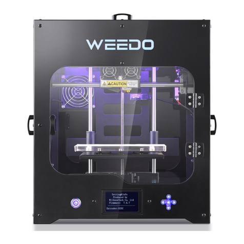
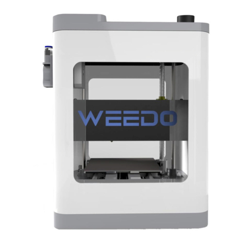
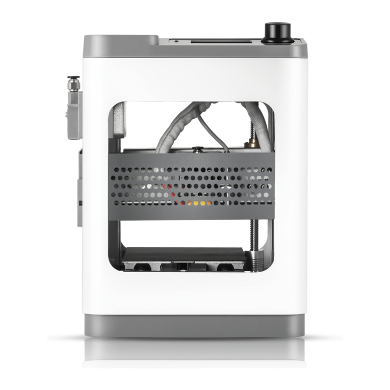
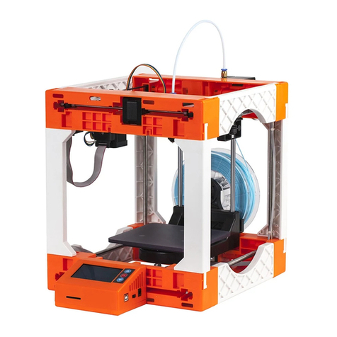
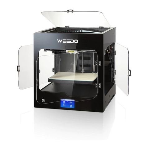
WEEDO F150S User manual

1
WEEDO F150S 3D Printer
User Manual

2
Contents
1. Application Notices........................................................................................................................................... 3
1.1. About the User Manual..............................................................................................................................3
1.2. Safety Precautions..................................................................................................................................... 3
1.3. Printing Consumables................................................................................................................................ 3
1.4. Environment requirements........................................................................................................................4
2. Introduction to the Printer................................................................................................................................4
2.1 Appearance Introduction............................................................................................................................4
2.2 Technical Parameters..................................................................................................................................5
3. Install the software of the printer.....................................................................................................................6
3.1 Install Wiibuilder software..........................................................................................................................6
3.2 Wiibuilder Instructions for advanced settings............................................................................................7
4. Print the first model......................................................................................................................................222
4.1. Connect the power supply.....................................................................................................................222
4.2 Loading the filament............................................................................................................................... 222
4.3 Printing preparation................................................................................................................................233
4.4 Printing Mode......................................................................................................................................... 233
4.5 Removing Model....................................................................................................................................... 23
5. Details of the Printing Operation....................................................................................................................24
5.1 Operation Panel Setting............................................................................................................................24
5.1.1 Introduction of the Operation Panel..................................................................................................... 24
5.1.2 Operation Panel Menu........................................................................................................................25
5.1.3 Common operations of the control panel.......................................................................................... 25
5.1.4 Printer Preheat....................................................................................................................................................................26
5.1.5 Debuggung of Printing Function...................................................................................................................................26
5.1.6 Filament Replacement.....................................................................................................................................................27
5.1.7 Printer Jog Bebugging.......................................................................................................................................................27
5.1.9. Auto Home............................................................................................................................................ 29
5.1.10. Stop printing/Pause printing...............................................................................................................30
5.1.11. Adjust the temperature...................................................................................................................... 31
6. Daily Repair and Maintenance.......................................................................................................................... 31
6.1. Printer Daily Maintenance Guide.............................................................................................................31
6.1.1.Clean and replace the nozzle ...........................................................................................................31
6.1.2 Replacing the tape of the glass plate.....................................................................................................32
7. Optical Shaft and Screw Rod Maintenance..............................................................................................................34
8.Printing Nozzle Maintenance and Replacement.......................................................................................................35

3
9. Frequently Asked Questions and Troubleshooting (FAQ)......................................................................................355
1. Application Notices
1.1. About the User Guide
This User Guide contains important information on the installation, use, maintenance and other questions
frequently raised up about the 3D printer. Please read this user guide carefully before using this 3D printer. For
damages to the 3D printer and other losses caused by the violation of safety precautions and operational
processes given in this User Guide, the user should take all the responsibilities.
1.2. Safety Precautions
1) The temperature of the nozzle would be up to 200 ℃during printing and after printing; therefore, it is
prohibited to directly touch the printing nozzle during these time.
2) The temperature of the printing platform would be up to 100 ℃during the printing of ABS consumables or
after printing; therefore, it is prohibited to directly touch the printing platform during these time.
3) The 3D printer is equipped with active air filtration system which can handle most of the irritant gases exuding
from the heated filaments during printing. For continuous printing of a long time, it is better to place the printer in
a well-ventilated environment.
4) The structure of this 3D printer is very complex; please refer to this user guide for troubleshooting. If the
problem still cannot be solved, please contact our after-sale service. Our company will not offer warranty for
printers with unauthorized repair by the user.
5) There is high voltage within the 3D printer and it is prohibited for non-professionals to disassemble the printer.
All the consequences for violation of this precaution should be the responsibility of the user.
6) Please use the power cord and the USB data cable supplied by our company. For printer failure and other
consequences because of using the third-party power cable or USB data cable, the user should take all the
responsibilities.
7) When the 3D printer is connected to the power, please plug the power cord into three-hole flat socket
complying with the international standard. The power cord cannot be forced into a two-hole socket. The ground
wire must be connected to the ground and shall not be suspended. Our company will not be responsible for
mechanical failure or other accidents caused by the disconnection of the ground wire.
8) The input voltage of the 3D printer is 100-220V. Please feel free to use it in or outside the mainland China.
9) If unexpected power outages are frequent in your area, please equip the 3D printer with UPS power.
1.3. Printing Consumables
Please use the printing consumables provided by our company for this printer. Printing consumables sold at the
retail market are different in specifications and varying in quality; As a result, it is easy to block the printer extruder,
damage the extruder and motor. Our company will not offer warranty for printer failure for using third-party
printer consumables.
1.4. Environment requirements
This 3D printer uses a fully enclosed structure, which means that it has strong adaptability to the ambient
temperature. It can work properly in an environment from 5 ℃to 40 ℃. If the ambient temperature is beyond
this range, the quality of the printing products will decline.
If the filaments will not be used for a long time, please store them in a sealed package, and it is especially true for
PLA consumables which will absorb moisture in prolonged exposure to air and affect the quality of finished
printing products.

4
2. Introduction of the Printer
The printer applies the FDM (Fused Deposition Modeling) principle, slice and convert the STL three-dimensional
model, then print out the physical object layer by layer. This printer has a series of innovative design such as a
metal frame, a fully enclosed structure, an electric heating platform with the characteristic of high printing speed,
good printing quality, easy to use, easy maintenance and supporting USB cable print.
2.1 Appearance Introduction
Front view of the Printer
○
1Up Cover ○
2Front Door ○
3Power socket
○
4LCD display screen ○
5Rotary Switch ○
6Printing platform
○
7Nozzle
Right view of the printer
○
1
○
3
○
2
○
6
○
7
○
5
○
4

5
○
1Filament holder ○
2SD card socket ○
3USB socket for printer
2.2 Technical Parameters
Printing parameters
Machine parameters
Printing Size
200*150*150mm
Display Type
English
Thickness of one
layer
0.1-0.4mm
Machine Size
380*340*420mm
Nozzle Diameter
0.4mm
Machine
Weight
15kg
Printing Speed
20-130mmmm/s
Input Voltage
100-240V,120W
Positioning
Accuracy
Z axis 0.0025mm
XY axis 0.011mm
Maximum
Power
24V,5A
Consumables parameters
Software parameters
Consumables Type
ABS /PLA/PLA Pro
Printing
software
Wiibuilder
Consumables
Diameter
1.75mm
File Format
STL/GCODE/OBJ
Consumables Color
Optional for mufti-colors
Operating
System
Windows/MacOS
○
1
○
3
○
2

6
Printing
mode
USB/SD Card
3. Install the Slicing Software of the Printer
Software
Wiibuilder
Wiibuilder is a host computer software for 3D printers, which can be sliced to
generate files for offline printing, online printing, 3D model editing, and
management of 3D printers. Wiibuilder uses a multithreading slicing engine,
including user interface and professional interface.
3.1 Install Wiibuilder software
Run the software installation package, Wiibuilder in the installation wizard window, click "next"-"next"-"Install"-
"finish". In the selection installation path window, use the default path of the program.

7
When you first time use Wiibuilder, you can set it up according to the software interface reminder.
When the software is started, parameters can be set up through the "configuration" menu in the
upper left corner of the software, choose “GUI choices" , “Easy GUI” is user interface, “Expert GUI"
is professional interface.
3.2 Wiibuilder Instructions for advanced settings
Open the Wiibuilder software, load the file that need to be printed, and click the "slicing" button in
the function bar on the top right side of the software.

8
Click the "advanced configure" , you will see the following interface:
There are nine settings in the settings box above the advanced settings menu, which are "speed",
"infill", "support", "build plate adhesion", "retraction", "material", "empty walk", "machine" and
“line width”.

9
In the settings box below the advanced settings menu, there are four settings, namely "dual
extrusion", "warping prevention", "seam" and "others".
3.2.1、"Speed" interface:
Top/bottom speed (mm/s): the printing speed of the upper and bottom surfaces of the model.
Outer shell speed (mm/s): the printing speed of the model shell.
Inner shell speed (mm/s): the printing speed of the shell in the model.
Infill speed (mm/s): the speed of infilling inside the printing model.
Support infill speed (mm/s): the printing speed of model support infilling;
Supporting interface speed (mm/s): the printing speed of the upper and lower surfaces of the
model support.
Initial layer speed (mm/s): the printing speed of the first layer of the model.
Travel speed (mm/s): the movement speed of the nozzle without entering the printing state.
The above parameter will be changed automatically when users change the speed in the basic
interface, so it is generally not necessary to change these parameter; If the speed of some parts is
specified, it can be set separately according to the demand.
3.2.2、"Infill"interface:
Infill pattern: the filling mode inside the model, the user can change the filling mode according to
the requirements of the intensity and beauty of the model to be printed, that is, to change the
filling shape inside the print model.
Click the "infill pattern" drop-down menu to select the filling mode, including lines, grid, triangle, zig

10
zag, concentric, cross and octet as follows:
The shape of each filling method is as follows:
Lines— ;Grid— ;Triangles— ;
Zig Zag— ;
Concentric— ;Cross— ;Octet— 。
Infill before walls: that is to choose whether to print the model after filling and print the outline.
Outer before inner: that is to choose whether to print the outline of the model before printing the
internal walls.
Gradual infill steps: that is, for the model that needs to gradually change the fill rate of the model,
determine how many layers change the fill rate once.
Generally, the above items do not need to be changed.
3.2.3、"Support" interface:

11
Support pattern: the supporting shape of the model, including lines, grid, triangles, zig zag and
concentric.
The drop down menu for the support mode is shown as follows: ,Users can set
different forms of support according to different models, so that support can be conveniently
removed and better support and model contact surfaces can be obtained.
Among them, lines, grid and zig zag shape support are mostly to be choose.
Lines support is applied to models which requiring more support, and it is easy easier to remove.
Grid support is applied to small models, which need fewer support models and support can be
removed.
Zig zag support is applied to some models which are particularly difficult to remove. The support of
this shape is stronger than that of the lines support and is better than the grid support.
Overhang angle: the angle between the support and the contact surface of the model, the size of
the angle will affect the use effect of the support and the difficulty of the later stage to remove the
support. The default setting is 60 degrees. The larger the angle is, the easier it is to remove the
support. The smaller the angle, the better the support effect.
Support filling density (%): the filling density of the support. The higher the filling density, the higher
the support strength; the lower the filling density, the lower the support strength.
Support top gap (mm): the distance between the top and the model surface, the larger the value
and the larger the distance, the support effect may be poor. The model adds the prop up, the
smaller the value and the smaller the distance, the surface will have residual material on the model
surface when the support is stripped from the model surface, which affects the model surface.
Smoothness; the user can print the test on the default value, up or down the parameter according
to the actual printing situation, so that the model gets better support effect and is easily stripped
from the model to get a better model surface.
Support bottom gap (mm): the spacing between the bottom of the support and the model surface,
which is similar to the adjustment mode of the above "support top distance model gap (mm)"
function.
Distance X/Y (mm): the spacing of the horizontal plane specified by the support distance model,
which is similar to the above "support top distance model gap (mm)" function adjustment.
Enable support: when the surface of the model needs to be added, the support surface can be
selected to obtain a better model surface.
Support top (mm): that is to support the thickness of the top surface, generally set the default.
Support bottom (mm): that is to support the thickness of the bottom surface, generally set the
default.

12
Support interface (%): that is, the filling rate of the supporting surface is generally set by default.
Support surface infill pattern: the filling mode of the supporting surface, including lines, mesh,
triangles, zig zag and concentric.
3.2.4、"Build plate adhesion" interface:
Raft air gap (mm): the space between the the adhesion and the model, the gap of the space
determines the difficulty of removing it from the model. See the following figure:
Raft extra margin(mm):That is, the distance between the adhesion edge and the model, it is
usually set by default.
Raft base thickness(mm):That is, the thickness of the model bottom adhesion, it is usually set by
default.
Initial layer Z overlap: it is the overlap rate between the first and second layers of the model printing,
and the default is generally set.
Brim line amount:that is the number of ring gaskets which added to the edge of the model contact
with the platform, it is generally set to the default.

13
Skirt line count :that is to add the anti overflow line at the edge of the model contact with the
platform, it is usually set by default.
3.2.5、"Retraction" interface:
In order to prevent stringing during printing process, retraction setup is added in the software.
Horizontal travel retraction: that is, when the nozzle is not printing, the nozzle will turn on the
retraction setting when horizontal movement.

14
Retract at layer change: that is to say, the nozzle will turn on the retraction setting when printing
different layers of the model.
Retraction speed (mm/s): that is, the retraction speed of the nozzle, which is usually set by default.
Retraction distance(mm):that is, the amount of material returned by the nozzle, which is usually
set by default.
Z hop height(mm):that is to say, when the nozzle returns material, the lifting amount of the
nozzle , which is usually set by default.
Retraction Minimum travel(mm):that is, the nozzle movement distance before printing and before
the nozzle retracting filaments, which is usually set by default.
3.2.6、"Material" interface:
Filament flow(%):that is, the flow rate of the consumables in the melting state,it is set according
to the consumable material. In general, the flow rate of PLA and PLA Pro is set to 90, and the flow
rate of ABS is set to 100.
Filament diameter(mm):that is, the diameter of the consumable material, according to the nozzle
diameter used by the printer and the line diameter of the consumable material, the diameter of the
consumable material of the WEEDO series printer is 1.75mm at present.
Automatic change temperature:when printing, the nozzle will automatically change the printing
temperature according to the temperature characteristics of the consumables, the general
consumables are set by default, no need to select.
3.2.7、"Travel" interface:

15
Combing Mode: when the nozzle is not printed, the way of the nozzle's running, including off, all
and no skin, it is usually set by default.
Start layers at same position: that is to change the accuracy of the model in the same plane, and it is
generally set the default.
Layer start position X(mm):that is, you want to change the X axis coordinates of the position of the
model layer.
Layer start position Y(mm):that is, you want to change the Y axis coordinates of the position of the
model layer.
3.2.8、"Machine" interface:
WEEDO series 3D printers include single nozzle and double nozzle machines. At present, the WEEDO
series 3D printers use the 0.4mm diameter nozzle.
3.2.9、“Line Width” interface

16
Outer Wall Line Width(mm): Width of the outermost wall line. By lowering this value, higher levels
of detail can be printed.
Inner Wall(s) Line Width(mm):Width of a single wall line for all wall lines except the outermost one.
Top/bottom Surface Skin Line Width(mm): Width of a single top/bottom line.
Infill Line Width(mm): Width of a single infill line.
Support Line Width(mm): Width of a single support structure line.
Skirt/Brim Line Width(mm):Width of a single skirt or brim line.
Raft Top Line Width(mm): Width of the lines in the top surface of the raft. These can be thin lines so
that the top of the raft becomes smooth.
Raft Middle Line Width(mm): Width of the lines in the middle raft layer. Making the second layer
extrude more causes the lines to stick to the build plate.
Raft Base Line Width(mm):Width of the lines in the base raft layer. These should be thick lines to
assist in build plate adhesion.
3.2.10、"Double nozzle" interface:
The interface is the parameter setting of WEEDO double nozzle series.

17
Standby temperature: that is when a double nozzle machine is printing, one of the nozzles stays at
the temperature waiting to be printed.
Prime tower: when the double nozzle model is printed, one of the nozzles is waiting to be printed.
The residual temperature of the nozzle leads to the overflow of the consumable material from the
nozzle. The erasing tower can erase the spillover of the nozzle, which is located on the side of the
print model, that is, the length of the side length of the waiting nozzle printing and erasing tower.
Ooze shield distance: when a double nozzle is printed, one of the nozzles is waiting to be printed.
The residual temperature of the nozzle leads to the overflow of the nozzle from the nozzle or
prevents the print head from touching the model and damages the model surface. Therefore, a
circle of protection layers is printed on the edge of the model, which refers to the protection layer
and the mode’s distance.
Support extruder, support interface extruder, build plate adhesion extruder and infill extruder: that
is to set up the printing support, the support surface, the bottom plate and the filled nozzle. In
general, the main part of the printing is the right head, which is generally set by default.
3.2.11、"Warping prevention" interface:
When printing a large model, the model can not be stuck well and easy to warping edge.
Parameters can be set under this column to prevent warping; there are three main ways:

18
1Z axis offset: when the Z axis bias is changed to negative, the gap between the model and
the print base plate is reduced, so that the model and the printing plate are pasted more
tightly to prevent the warping.
2The extra contour of the surface layer is to increase the number of contour in the outer
contour of the surface of the model and the printed plate, so that the contact surface of
the model bottom and the print floor is greater, so as to prevent the warping edge.
○
3 the initial layer temperature increment: that is to set the model to print the first layer
temperature higher than the later printing temperature, and the high temperature will make the
bottom layer of the model stick more firmly and prevent the warping edge.
After changing the parameters, the printing results of the above models are as follows:
3.2.12、"Seams" interface:

19
If the general model is not set, there will be concave lines or dots after printing.
The right picture is the state of the model in the software, that is, the concave line or point on the
solid model is a blank joint.
Therefore, when the model is sliced, the "seam" should be set.
Joint type:As a picture
The position of the seams in the printing model is the nearest position. The printing model effect is
as follows:
Set the seam position of the printing model as the specified position. The printing model effect is as
follows:

20
The joint position of the printing model is set at random, and the printing model effect is as follows:
The setting of the printing model is the sharp corner position. The printing model effect is as
follows:
Joint position X coordinates: determine the X axis coordinates of the specified joint position.
Joint position Y coordinates: determine the Y axis coordinates of the specified joint position.
The seam concealment: the seam will be hidden, and there will be no concave lines or dots on the
surface of the printing model.
The relative position of the seams is determined by determining whether the joint position is
relatively set or not.
3.2.13、"Other" interface:
Table of contents
Other WEEDO 3D Printer manuals