WEEDO X40 User manual

X40/X40V2 3D Printer
Quick Start Guide
INTRODUCTION
Thank you for purchasing this X40/X40V2 3D Printer! This printer uses the FFF (Fused Filament Fabrication) method of
printing. It features a metal frame, open structure design and heated build platform. It can print 1.75mm ABS, PLA,
Metal fill, Wood fill, and other filament types with melting points below 250°C (Default hot end). The machine with
independent dual extruders can print at a speed up to150mm/s and 300x300x400mm printing area. It can print from
sliced g-code files stored on a micro SD™ card or from our App (Poloprint Pro). It supports auto-leveling, automatic
shut-down, with a 4.3-inch touch screen, a removable and a heated build plate.
CUSTOMER SERVICE
The WEEDO Customer Service department is dedicated to ensuring that your ordering, purchasing, and delivery
experience is second to none. If you have any problem with your order, please give us an opportunity to make it right.
You can contact a WEEDO Customer Service representative through the Live Chat link on our website www.weedo.ltd
or via email at support@weedo3d.com. Check the website for support times and links. You can also search our
product wiki website: www.weedo3dprinter.com.

NOTES
Children are not allowed Pay attention to the voltage
Prevent pinching and cutting Keep clean and dry Safe operation
The temperature of the nozzle parts
and platform can reach 250°C .It is
forbidden to touch while the printer
is printing or cooling.
Please check whether the input voltage
value of the switching power supply meets
the standard of the country or region.
Please pay attention to the sharp edges
and corners of the profile.
If something goes wrong with the
machine, please contact our after-sales
service.
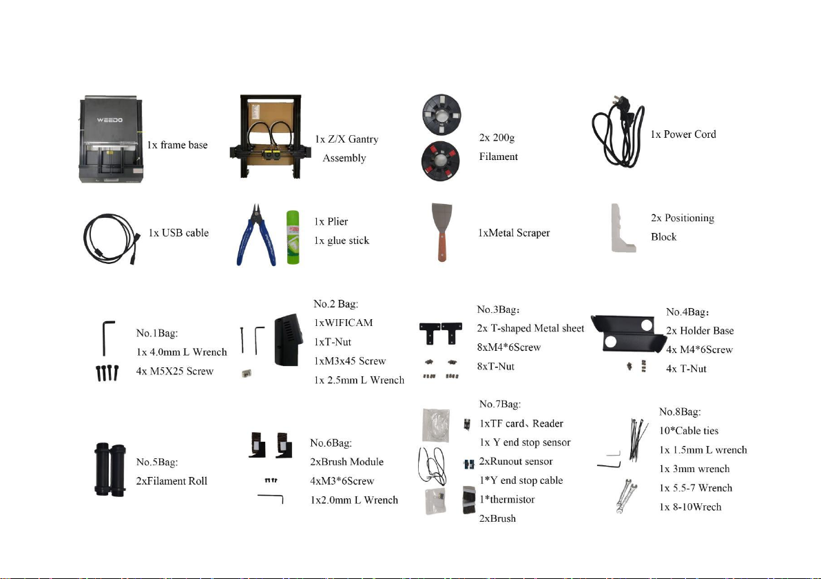
PARTS LIST

OVERVIEW
Left view
Right view
12
13
14
15
1. Left X End Stop Sensor
2. Proximity
3. Left Extruder
4. Start Button
5. Touch Screen
6. Wi-Fi Camera Module
7. Build Platform
8. Nozzle brush
9. Right Extruder
10. Right X End Stop Sensor
11. Filament Holder
12. Power Interface
13. Power switch
14. TF slot
15. Voltage regulator
switching
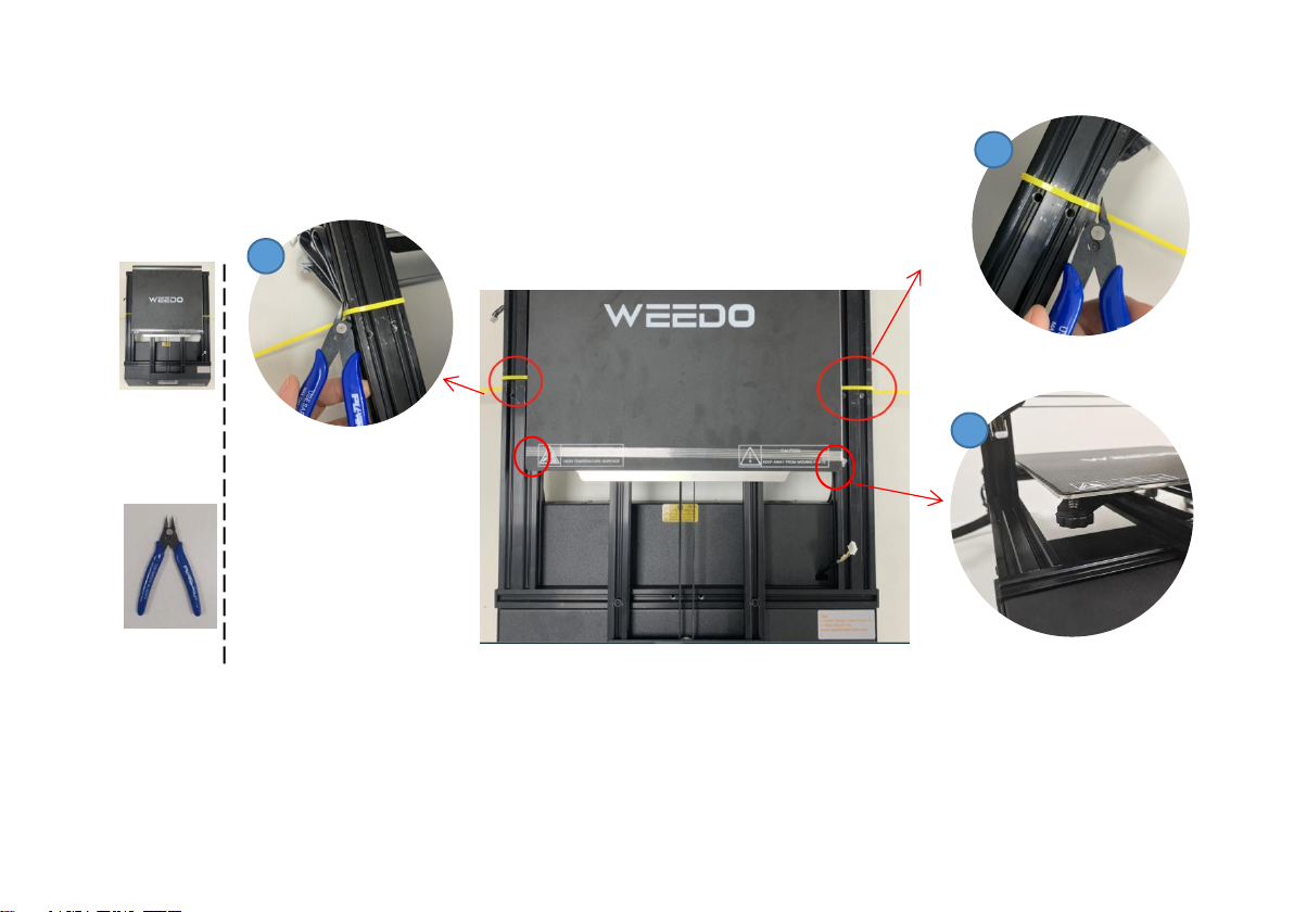
1. Cut the tie on the frame base.
2. Tear off the tape and make sure the platform does not move.
3. Check that the four Leveling Nuts are not falling off. Tighten them.
2
1x 3D
printer
Frame
base
1x pliers
Step 1: Open the accessory box and get the frame base
3
Tips: Do not cut the
cables on the host!
Tips: There are slight scratches on the aluminum profile because the machine has been installed and
tested before leaving the factory, Which is a normal phenomenon.
1

4
No.1Bag:
1x 4.0mm L
Wrench
4x M5X25
Screw
Step 2: Install the Z/X Gantry onto the base
2
3
5
1
4. Pour the base to the right,pluck
the wire above the screw hole
with your finger.
Tips:Be careful not to let the screw
through the wire during installation
and press the sprinkler line when
moving the machine.
2. Take a foam on the
right side of the base.
1. Place the Z/X Gantry
above the base.
Tips: If the right extruder
pneumatic coupling falls off,
it needs to be retwisted with a
wrench.
3. Screw the M5X25 into the
hole with an L-shaped
4.0mm wrench.
Tips: If it's deformed,you can
align the Gantry with the base
so that the screw goes into the
screw hole.
5. Adjust the direction of the
wrench, insert the short side ,
tighten all screws forcefully.
1
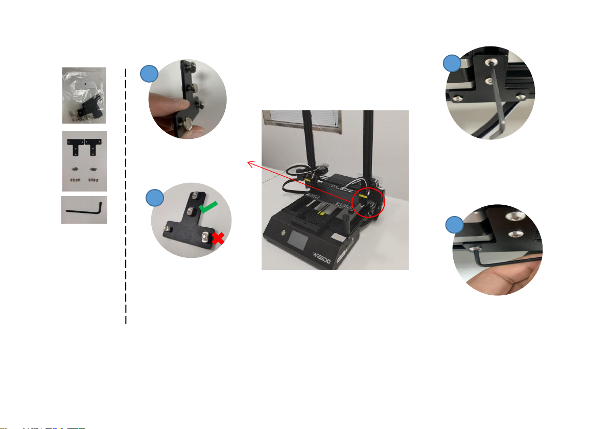
Step 3: Install T-shaped fixtures on both sides of the
printer
2
4
Tips:Pay attention to the installation
direction of T-nut.
Tips:Get the 2.5mm L wrench ready, it will be used in the next step.
No.2Bag:
1x 2.5 mm L Wrench
No.3Bag:
2x T-shaped Metal
sheet
8x M4*6Screw
8x T-Nut
1. Install screws and T-nuts
on T-shaped fixtures by
hand.
2. Insert the long side of
the 2.5mm L-shaped
wrench into the screw cap.
4. Adjust the L-shaped wrench
and insert the screw cap with the
short side to tighten all screws.
3. Screw the four screws on the
T-shaped fixture into the
aluminum profile, rotate the T-nut
to 90-degrees.
3

Tips: Make sure the cables are connected and fastened.
3
1
2
Step 4: Connect the Y and Z Motor Cable and Extruder Cable
1. Connect the Y Motor Cable on the
back of the host, check the Y end
stop sensor is installed properly.
2. Plug the motor cable and sprinkler
cable on both sides of the printer
respectively.

No.2Bag:
1x WIFICAM
1x 2.5mm L Wrench
1x M3x45 Screw
1x T-Nut
3
1
Step 5: Install the WIFICAM module
Tips: Hide the cables so the platform
won't scratch them
1. Insert the M3X45 screw into the
WIFICAM module with the long edge
of the L-shaped wrench.
2. Screw the T-nut on the
M3X45 screw by hand.
2
3. Connect the cable to the
WIFICAM module, Install the
WIFI module on the front right.
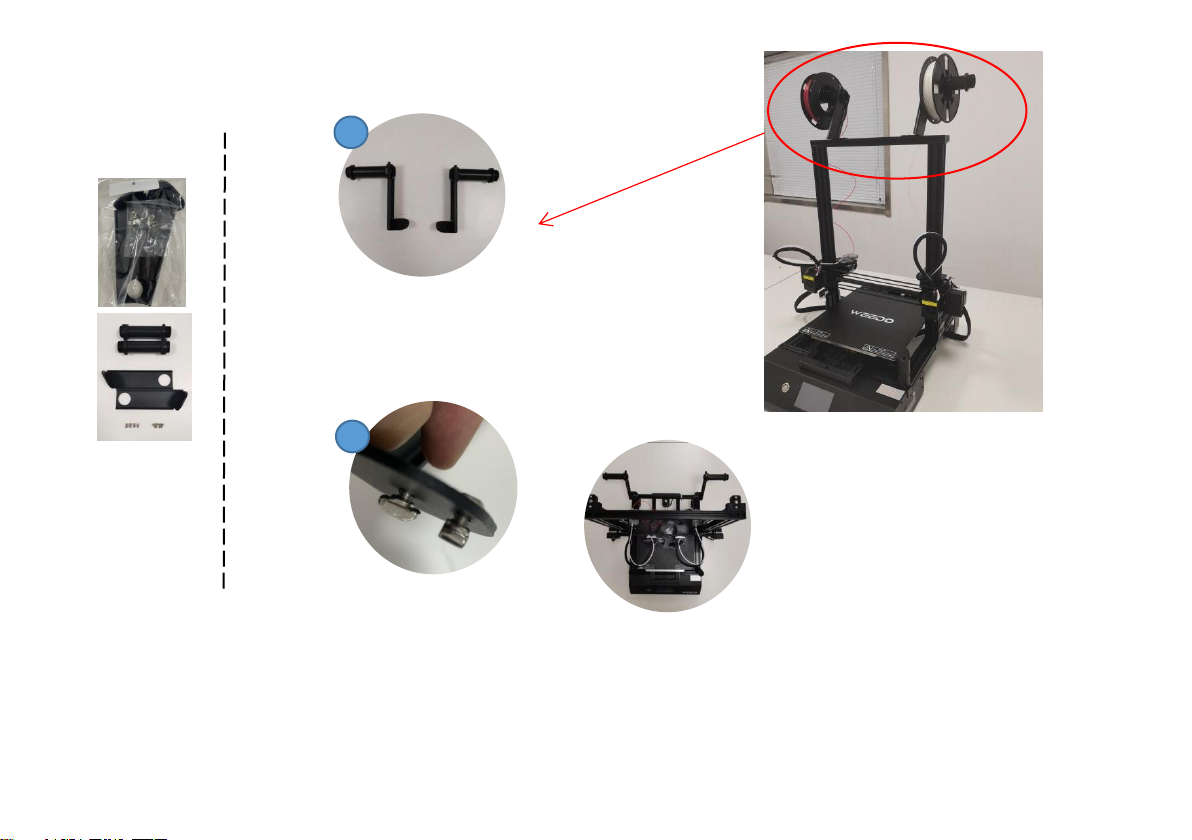
Tips: The filament holder installation location shown below is recommended by WEEDO X40 users. If your machine has limited
space, you can also install the holder on the aluminum profile bar at the top of the printer.
No.4/5 Bag:
2x Filament Roll
2x Filament Holder
4x M4*6Screw
4x T-Nut
1
2
Step 6: Install the Filament Holder
1. Screw the Round tube to the
filament holder.
2. Install the filament holder to
the top beam, about 9 inches
apart between two holders.
Other manuals for X40
2
This manual suits for next models
1
Table of contents
Other WEEDO 3D Printer manuals


