manuals.online logo
Brands
  1. Home
  2. •
  3. Brands
  4. •
  5. WAGO
  6. •
  7. Circuit Breaker
  8. •
  9. WAGO EPSITRON 787-1662 User manual

WAGO EPSITRON 787-1662 User manual

Funktionsschaltbild
Function diagram
Schéma fonctionnel
CONTROL UNIT
LOAD 1 LOAD 4LOAD 3
S1
OUT 1(+)
IN 4 (–) IN 2 (+)IN 3 (–) IN 1 (+)
OUT 4(+)OUT 3(+)
+
S2
–
S3
AC
DC
DC 24 V
LOAD 2
OUT 2(+)
MAX. 40 A
deutsch
Der elektronische Schutzschalter teilt den Laststrom auf mehrere 24-V-Abzweige auf
und überwacht sie zuverlässig auf Überlast und Kurzschluss. Kurzfristige Strom-
spitzen, z.B. durch einen hohen Einschaltstrom, lässt die Elektronik zu, Abzweige mit
längerer Überlast schaltet sie stromlos.
Der Auslösestrom eines jeden Ausgangs kann individuell mit einem von vorne zugäng-
lichen Stromwahlschalter eingestellt werden. Die Ausgänge werden zeitversetzt und
lastabhängig eingeschaltet, um Spitzeneinschaltströme zu verringern. Bei Überschrei-
tung des Nennstromes wird der Ausgang nach einer definierten Auslösezeit automa-
tisch abgeschaltet und kann nach einer kurzen Wartezeit (thermische Entspannung)
mittels Taster oder per Signalkontakt wieder eingeschaltet werden. Der Taster dient
ebenfalls zum manuellen Abschalten des jeweiligen Ausgangs. Über Signalkontakte
lassen sich betriebsrelevant e Informationen auslesen als auch gezielt einzelne Ausgän-
ge ein- oder ausschalten. Über eine mehrfarbige LED wird der Status des jeweiligen
Ausgangs angezeigt.
Funktionsbeschreibung
Bitte lesen Sie diese Warnungen und Sicherhinweise sorgfältig durch, bevor Sie das
Gerät in Betrieb nehmen. Das Gerät darf nur durch fachkundiges und qualifiziertes
Personal installiert werden. Bei Funktionsstörungen oder Beschädigungen schal-
ten Sie sofort die Versorgungsspannung ab und senden das Gerät zur Überprüfung
ins Werk. Das Gerät beinhaltet keine Servicebauteile. Bei Auslösen einer internen
Sicherung liegt höchstwahrscheinlich ein interner Defekt am Gerät vor. Die angege-
benen Daten dienen allein der Produktbeschreibung und sind nicht als zugesicherte
Eigenschaften im Rechtssinne aufzufassen.
Bestimmungsgemäßer Gebrauch
Dieses Gerät ist für den Einbau in ein Gehäuse konzipiert und zur Verwendung für allge-
meine elektronische Geräte, wie z.B. Industriesteuerungen, Bürogeräte, Kommunikati-
onsgeräte oder Messgeräte geeignet. Benutzen Sie dieses Gerät nicht in Steuerungs-
anlagen von Flugzeugen, Zügen oder nuklearen Einrichtungen, in denen eine Funktions-
störung zu schweren Verletzungen führen oder Lebensgefahr bedeuten kann.
Installation
Die Installation ist entsprechend den örtlichen Gegebenheiten, einschlägigen Vor-
schriften, nationalen Unfallverhütungsvorschriften und den anerkannten Regeln der
Technik durchzuführen. Dieses elektrische Betriebsmittel ist eine Komponente, die
zum Einbau in elektrische Anlagen oder Maschinen bestimmt ist und erfüllt die Anfor-
derungen der Niederspannungsrichtlinie (2006/95/EG). Der geforderte Mindestab-
stand zu benachbarten Teilen ist einzuhalten, um die Kühlung nicht zu behindern!
Vor Inbetriebnahme lesen
Bedienelemente
Fig. 1
1
2
3
4
5
6
Plombierbare Abdeckung der Stromwahlschalter
Eingang (+24 V und 0 V)
Der Anschluss 0V dient nur der Eigenversorgung des Schutzschalters.
Ausgänge zum Anschluss der Verbraucherkreise. Die 0 V der Verbraucher sind
über getrennte Leitungen direkt zur Stromversorgung zu führen.
Stromwahlschalter
Taster An/Aus/Reset mit integrierter LED
Signal- und St euerkontak te S1 /S2/S3
S1= 24 V - Eingang (Ein/Aus/Reset )
S2= 24 V - Ausgang (Status aller Ausgänge)
S3= 24 V - Ausgang (Sammelmeldung für ausgelöste Ausgänge)
Betriebszustände,
Signalisierung, Reaktionen
1) Nach Abschluss der Modulinitialisierung werden die Ausgänge lastabhängig eingeschaltet.
2) Der Ausgang wird gemäß Auslösekennlinie automatisch abgeschaltet. Bei Abschaltung Übergang nach
Betriebszustand Z4.
3) Der Zust and jedes Ausgangs wird beim Ausschalt en des Gerätes gespeichert.
4) Nach einer Wartezeit (thermische Entspannung) Übergang nach Betriebszustand Z5. Beim Ausschalten
des Gerätes wird die restliche Wartezeit gespeichert und beim Wiedereinschalten abgewartet. Dadurch
wird auch bei sofortigem Wiedereinschalten des Gerätes eine Überlastung der Schaltelemente zuverlässig
verhindert.
5) Der betroffene Ausgang kann durch zweimaligen Tastendruck oder über einen Impuls (> 0,5s) an
Signaleingang S1 wiedereingeschaltet werden, Übergang nach Betriebszustand Z1.
Betriebszustand /
Beschreibung Ausgang LED Signalausgang S3
(Summensignal)
Taster wird gedrückt
=> Übergang nach...
Steuereingang S1
=> Übergang nach ...
Z 0 Modulinitialisierung 1) aus aus 0 V --- ---
Z 1 Ausgang eingeschaltet,
Funktion OK
ein grün 24 V Z 3 Z 3 (via Bitmuster)
Z 2 Ausgangsstrom >
Nennstrom 2)
ein grün
blinkend
24 V Z 3 Z 3 (via Bitmuster)
Z 3
Ausgang ist manuell
oder per Signaleingang
S1 abgeschaltet 3)
aus rot 24 V Z 1 Z 1 (via Bitmuster)
Z 4
Ausgang ist aufgrund
eines Überstroms ab-
geschaltet, thermische
Entspannung aktiv 4)
aus rot
blinkend
0 V --- ---
Z 5
Ausgang ist aufgrund
eines Überstroms
abgeschaltet, thermi-
sche Entspannung ist
beendet 5)
aus orange
blinkend
0 V Z 3 Z 1 (mittels Impuls > 0,5s)
Z 6 Gerätefehler (defekte
Sicherung detektiert)
aus rot schnell
blinkend
0 V Z 6 ---
Prüfzeichen
Markings
Approbation
U o
UL 2367 UL 508 Germanischer Lloyd
EPSITRON - Elektronischer Schutzschalter
EPSITRON - Electronic fuse unit
EPSITRON - Disjoncteur électronique
EPSITRON ®787-1662 787-1662/0106-0000
787-1664 787-1664/0106-0000
deutsch / english / français
Bedienungsanleitung / Instruction Manual / Manuel d‘utilisation
1
2
3
4
5
6
Fig. 1
787-1662/1664/0106-0000 / 2015•02
english français
The electronic circuit breaker distributes and monitors the load current over several
current circuits. Overloads and short circuits on an output are reliably recognized.
The electronics permit brief current peaks and switch longer overloads off. The rated
current for each output can be individually set with a current- selector -switch acces-
sible from the front. The outputs are time-delay and load-depend activated to avoid
overload current.
If the rated current is exceeded for a cer tain time, the output will be switched off au-
tomatically and can be switched on after a waiting time (thermal relaxation) using the
pushbutton or the remote signal-input S1. The pushbutton can also be used to switch
the output manually. It is possible to read out the state of each output using the three
signal contacts. The state of each output is also indicated with a multi-colored LED.
Product Description
Le disjoncteur électronique permet la distribution du courant de charge sur plusieurs
sorties 24 V DC et les contrôle fiablement en cas de surchage ou court-circuit. La
protection électronique autorise des pics de courant tel qu’un courant d’appel élevé au
démarrage. Elle se désactivera en cas de charges plus longues.
Le courant de déclenchement de chacune des sorties peut être paramétré
individuellement via les sélecteurs situés à l’avant de l’appareil. Les sorties sont
activées avec un décalage en tenant compte des charges afin d’éviter les pics de
courant. En cas de dépassement du courant nominal, la sortie sera automatiquement
désactivée après un délai de déclenchement défini et pourra après un bref temps
d’attente (détente thermique) être réactivée à l’aide du bouton ou de l‘entrée de
commande S1. Le bouton sert aussi pour la désactivation manuelle des sorties
respectives. Il est possible de visualiser les états de fonctionnement via les sorties de
signalisation, ainsi que d’activer ou désactiver individuellement les sorties. L’état des
sorties sera indiqué individuellement par une LED multicolore.
Fonctionnement général
Before operating this unit please read the manual thoroughly. This device may only be
installed and put into operation by qualified personnel. If damage or malfunction should
occur during operation, immediately turn power off and send unit to the factory for
inspection. The unit does not contain serviceable parts. The tripping of an internal fuse
is caused by an int ernal defect.
The information presented in this document is believed to be accurate and reliable and
may change without notice.
Intendend Use
This device is designed for installation in an enclosure and is intended for general use
such as in industrial control, office, communication, and instrumentation equipment.
Do not use this device in aircraft, trains and nuclear equipment where malfunction may
cause severe personal injury or threat en human life
Installation
Installation must be carried out according to the prevailing local conditions and safety
regulations, national accident prevention regulations and the generally accepted rules
of technology. This equipment is a component designed for installation into electrical
systems and machines, and fulfills the requirements of the low voltage guidelines
(2006/95/EG). The required minimum spacing to neighboring components must be
observed to guarantee the required cooling!
Read this first
Veuillez lire soigneusement ces avertissements et consignes de sécurité avant de
mettre l’appareil en service. L’appareil ne doit être installé que par du personnel
compétent et qualifié. En cas de dysfonctionnement, couper immédiatement la tension
d’alimentation et retourner l’appareil à l’usine pour vérification. L’appareil ne contient
pas de pièces échangeables. En cas de déclenchement d’un fusible interne, l’appareil
présente vraisemblablement un défaut. Les données indiquées sont à but descriptif.
Elles ne doivent pas être interprétées comme des caractéristiques assurées au sens
juridique du terme.
Usage conforme
Cet appareil est conçu pour être installé en armoire et convient à une utilisation sur
des installations électriques générales telles que des commandes industrielles, des
appareils de bureau, de communication ou de mesure. Ne pas utiliser cet appareil à
bord des commandes d’avions, de trains, ou installations nucléaires, dans lesquelles un
dysfonctionnement peut entrainer des blessures graves ou signi fier un risque mor tel
Installation
L’installation doit être réalisée conformément aux recommandations locales, aux
directives nationales relatives à la prévention des accidents ainsi que les normes
techniques reconnues. Cet équipement est un composant destiné à un montage
sur des systèmes et des machines électriques. Il est conforme aux conditions de la
Directive Basse tension (2006/98/CE). La distance minimale requise avec les modules
avoisinants doit être respectée afin de ne pas entraver le refroidissement.
A lire avant la mise en service
1
2
3
4
5
6
Sealed cover of the current-selector-switches
DC input (+24 V and 0 V)
The 0 V connection of the device merely serves to supply the internal electronic
circuits.
Outputs for connecting the load circuits. The 0 V of the loads must be supplied
directly to the power supply by means of separate lines.
Current-selector-switches
Pushbuttons On/Of f/Reset with integrated LED
Signaling contacts S1/S2/S3
S1= 24 V - input (On/Of f/Reset)
S2= 24 V - output (status output channels)
S3= 24 V - output (Summation message for tripped output s)
User elements
Fig. 1
1
2
3
4
5
6
Capot de protection des sélecteurs
Entrée DC (+24 V et 0 V).
La connexion du 0 V est utilisée uniquement pour l‘alimentation du disjoncteur
Sorties pour le raccordement des charges. Le 0 V des charges doit être raccordé
directement à l‘alimentation électrique par des câbles séparés.
Sélecteur
Bouton marche/ arrêt / réinitialisation avec LED intégrée
Commande S1 et sor ties de signalisation S2/S3
S1 =24 V- Entrée (Marche/arrêt/ Réinitialisation)
S2= 24 V- Sortie (indique l’état de fonctionnement de toutes les sorties)
S3= 24V - Sortie (message collectif pour toutes les sorties déclenchées).
Eléments de commande
Fig. 1
Operating states,
Signaling, Reactions
Etats de fonctionnement,
signalisation, réactions
1) After the initialization of the device the outputs are switched on (load dependent).
2) The output is automatically deactivated in accordance with tripping-curves-characteristics.
3) The state is saved at power- o f f of all output s.
4) After a specific time interval (Thermal relief) change to operational condition Z5. If the unit is switched off
the remaining time is saved and will resume with the next switch on. This reliably prevents overloading if the
unit is immedia tely sw itched back on.
5) The affected output can be reset by pressing the push button twice or through an impulse (>0,5s) on signal
input S1. Change to operational condition Z1.
1) Une fois le module initialisé, les sorties seront activées dépendamment de la charge.
2) La sortie est désact ivée automatiquement conformément à la carac t éristique de déclenchement
3) L’é tat de fonc tionnement de chaque sortie est enregistré à la coupure de l’appareil.
4) Après un délai d’attente (détente thermique), la sortie peut être réactivée. Le temps d’attente restant est
enr egistré lors de la coupur e de l’appar eil et son expiration se f era au redémarrage.
5) La sortie concernée peut être réinitialisée en pressant 2 X sur le bouton ou via une impulsion (>0.5s) sur la
l‘entrée de commande S1 , passage à l‘état Z1.
State / Description Output LED Signal output S3
(Summation)
Pushbutton pressed
=> go to...
Signal input S1
=> go to...
Z 0 Initialization 1) off off 0 V --- ---
Z 1 Output on, function OK on green 24 V Z 3 Z 3 (via bit-streaming)
Z 2 Output current > rated
current 2)
on green
flashing
24 V Z 3 Z 3 (via bit-streaming)
Z 3
Output was switched
off manually or through
signal input S1 3)
off red 24 V Z 1 Z 1 (via bit-streaming)
Z 4
Output was switched
off automatically (over
current), thermal
relaxation active 4)
off red
flashing
0 V --- ---
Z 5
Output was switched
off automatically (over
current), thermal
relaxation finished 5)
off orange
flashing
0 V Z 3 Z 1 (through impulse > 0,5 s)
Z 6 Output malfunction
(internal fuse blown)
off red flasing
fast
0 V Z 6 Z 6
Etat de fonctionnement /
Description Sortie LED Sor tie de signal S3
Message collectif
Bouton est actionné
=> aller à...
Entrée de commande S1
=> aller à...
Z 0 Initialisation de module 1) arrêt arrêt 0 V --- ---
Z 1 Sortie activée, Fonction OK marche vert 24 V Z 3 Z 3 (via configuration
binaire)
Z 2 Courant de sortie > Courant
nominal 2)
arrêt clignote
vert
24 V Z 3 Z 3 (via configuration
binaire)
Z 3
La sortie est déactivée
manuellement ou par l‘entrée de
signal S1 3)
arrêt rouge 24 V Z 1 Z 1 (via configuration
binaire)
Z 4
La sortie est désactivée en raison
d‘un courant de surcharge,
détente thermique active 4)
arrêt clignote
rouge
0 V --- ---
Z 5
La sortie est désactivée en raison
d‘un courant de surcharge,
la détente thermique est terminée 5)
arrêt clignote-
orange
0 V Z 3 Z 1 (par impulsion
>0,5 s)
Z 6
Erreur de l‘appareil (fusible interne
défectueux détecté)
arrêt clignote
rapidement
rouge
0 V Z 6 Z 6
787-1664
787-1662
787-1664/0106-0000
787-1662/0106-0000
Eingangsdaten Input data Entrée
Output: 2 - 10 A / channel Output: 1 - 6 A / channel
Eingangsnennspannung Nominal input voltage
Tension nominale d‘entr ée
DC 24 V
Eingangsspannungsbereich Input voltage range
Plage de tension d‘entr ée
18 - 30 Vdc
Maximale Restwelligkeit/Rippel der spei-
senden Eingangsspannung
Maximal residual ripple of supplied input
voltage
Ondulation résiduelle maximale/ondulation
de la tension d‘entrée d‘alimentation
3%
Erforderliche Eingangsspannung zum
Einschalten der Ausgänge
Required input volt age for turning on of
outputs
Tension d‘entrée requise pour l‘acti vation
des sorties
20 V
Max. Dauerstrom des Moduls Max. total input curr ent Courant permanent max. du module
4 channel: 40 A
2 channel: 20 A
4 channel: 24 A
2 channel: 12 A
Max. Dauerstrom pro Klemmenpol Max. inpu t curr en t for each pole of terminal Courant permanent max . par pôle de borne 40 A
Überspannungsschutz
Suppressordiode
Over voltage protection
Suppressor diode
Protection contr e les surtensions
Diode transil
33 V
Ruhestrom im Leerlauf @ 24 V St and- by current @ 24 V Courant de repos à vide @ 24V 35 mA
Verlustleist ung im Leerlauf @ 24 V Power losses in st and- by mode @ 24 V Perte s en puissance à vide @ 24V 0,84 W
Anschlüsse Eingang Terminals input Raccordement entrée WAGO Series 831, max 6 mm² (2 x „+“)
WAGO Series 721, max 2,5 mm² (2 x „- “)
Ausgangsdaten Output data Sortie
Ausgangsnennspannung Nominal ou tput volt age Tension nominale de sortie DC 24 V
Ausgangsnennströme
einstellbar
Nominal output current
adjustable
Courants nominaux réglable des sorties 4 channel: 4 x (2, 3, 4, 6, 8, 10 A)
2 channel: 2 x (2, 3, 4, 6, 8, 10 A)
4 channel: 4 x (1, 2, 3, 4, 5, 6 A)
2 channel: 2 x (1, 2, 3, 4 , 5, 6 A)
Maximaler Spannungsabfall zwischen Ein-
und Ausgang
Maximum voltage drop between input and
output
Chute de tension ma ximale entre entr ée
et sortie
4 channel: 200 mV @ 4 x 10 A
2 channel: 200 mV @ 2 x 10 A
4 channel: 120 mV @ 4 x 6 A
2 channel: 120 mV @ 2 x 6 A
Modulinitialisierungszeit Initialization time Temps d‘initialisation de module 250 ms
Zuschaltverzögerung der Kanäle
lastabhängig
Turn-on delay of outputs
load dependent
Retard d‘ac tivat ion des canaux
selon la charge
min. 50 ms / ma x. 5 s
Wartezeit nach Abschaltung eines Aus-
gangs (Thermische Entspannung)
Kur zschluss (A ) ... Überlast (B)
Waiting periode after switch- o f f of an
output (thermal relaxation)
short circ uit (A) ... overload (B)
Temps d‘attente après mise hors service
d‘une sortie (dét ent e ther mique)
court-cir cuit (A) ... surcharge (B )
500 ms (A) … 20 s (B)
Maximale Verlustleistung Maximum power losses Perte s en puissance ma ximales 4 channel: 10 W @ 4 x 10 A
2 channel: 5,5 W @ 2 x 10 A
4 channel: 4,2 W @ 4 x 6 A
2 channel: 2,5 W @ 2 x 6 A
Wirkungsgrad Efficiency Rendement 99%
Maximale Last kapazität pro Ausgang Maximum turn-on capaci t y for each output Charge capacitive maximale par sortie > 50 … 500 mF
Integrierte Ausgangssicherungen pro
Ausgang
Internal ou tput fuse for each output Fusibles de sortie in terne par sortie 15 A
Rückspeisefestigkeit Resist ance to reverse feed ma x. Tension de retour max. 35 V
Parallelschaltung von Ausgängen Parallel use of output s Mon tage en parallèle de sorties -
Serienschaltung von Ausgängen Serial use of ou tputs Mon tage en série de sor ties -
Anschlüsse Ausgänge Terminals outputs Raccordement sorties 4 channel: Wago Series 721, max 2,5 mm² (4 x „+“ )
2 channel: Wago Series 721, max 2,5 mm² (2 x „+“)
Signalisierung Signaling Signalisation
Statusanzeige (pro Ausgang)
LED (r ot, grün, orange)
Status display (for each output)
LED (r ed, green, orange)
Indication du statut (par sortie)
LED (r ouge, verte, orange )
√
Signaleingang S1
(Ein/Aus/Reset)
Signal input S1
(On/Off/Reset)
Entr ée de commande S1
(Marche/Arrêt/Réinitialisation)
DC 24 V
Level high = min. 15 V, max. 30 V
Level low = min. 0 V, ma x. 5 V
Jitter: ± 5 % or ± 5 ms
Signalausgang S2
(Zustand der Ausgänge, kurzschlussfest)
Signal output S2
(status output channels, shor t circui t
proof)
Sortie de signalisation S2
(interrogation de l‘état des sorties, résis-
tant au cour t-cir cuit)
DC 24 V, max. 25 mA
Signalausgang S3
(Sammelmeldeausgang, kurzschlussfest)
Signal output S3
(summation message, short circuit proof)
Sortie de signalisation S3
(sor tie de message collec t if, résist an t au
court-circuit)
DC 24 V, max. 25 mA
S3 = 24 V: Status OK
S3 = 0 V: minimum one channel is t ripped
Anschlüsse Signalisierung Terminals signaling Raccordement signalisation WAGO Series 721, max 2,5 mm² (S1, S2, S3)
Umwelt Environment
Environnement
Lagertemperatur Storage temperature Température de stockage -25 °C ... +85 °C
Umgebungstemperatur Operational temperature Température ambiante -25 °C ... +70 °C
Konvektionskühlung Convection cooling Refroidissement par convection √
Luftfeuchtigkeit, keine Betauung Humidity, no condensation Humidi té de l‘air , absence de condensation 5 … 96 %
Einsatz in Bereichen mit
Verschmutzungsgrad 2
For installation in Pollution
Degree 2 environment
Pour installation dans un
environnement de pollution 2
√
Zum Anschluss Kupferkabel mit min. 60 °C
oder 60/75 °C verwenden
Use Copper Conductors only, rated 60 °C
or 60/75 °C
Utiliser uniquement des câbles de conne -
xion en cuivre supportant des plages de
températur es 60 °C ou 60/ 75 °C
√
Derating Derating Derating Max. out put current per channel:
10 A
total current (all channels
togehther):
max. 40 A @ 40 °C
max. 35 A @ 50 °C
max. 25 A @ 60 °C
max. 20 A @ 70 °C
no Derating
Erforderlicher Mindestabstand (seitlich) Required minimum spacing (left/right) Distance minimale requise (latérale) -
Erforderlicher Mindestabstand (oben/
unten)
Required minimum spacing (over/under) Distance minimale re quise (en haut /en bas) 40 mm
Allgemeine Daten G eneral data Données générales
Schutzar t nach IEC 60529 Degree of pr otection acc . to IEC 60529 Type de protection selon EN 60529 IP 20
Schutzklasse nach EN 61140 Protection class ac c. to EN 61140 Classe de protection selon EN 61140 III
Normen Safety standards Normes
Sicherheit Safety Sécurité EN 60950-1, EN 50178, EN /IEC 60204-1
EMV EMC CEM EN 61000-6-2, EN 61000-6-3
Schutzkleinspannung (SELV/PELV) Sa fet y extra- low volt age (SELV/PELV ) Trè s basse tension de sécuri té (TBT S/
TBTP)
IEC 60364- 4- 41 (DIN VDE 0100-410)
CE gemäß 2004/108/EG (EMV-Richtlinie) CE ac c. to 2004/108/ EG (EMC- Directive) Conf or me à la directi ve 200 4/108/EG
(CEM)
√
Prüfzeichen
Markings Approbation
UL 2367 UL 2367 UL 2367 Special-purpose Solid-state overcurrent protectors
UL 508 UL 508 UL 508 List ed for the use as Industrial Cont rol Equipment;
U.S.A. (UL 508) and Canada
GL GL
GL
GL (Germanischer Lloyd) classified, Environmental cat egor y: C, EMC2
Mechanische Daten Measures and weights Caractéristiques mécaniques
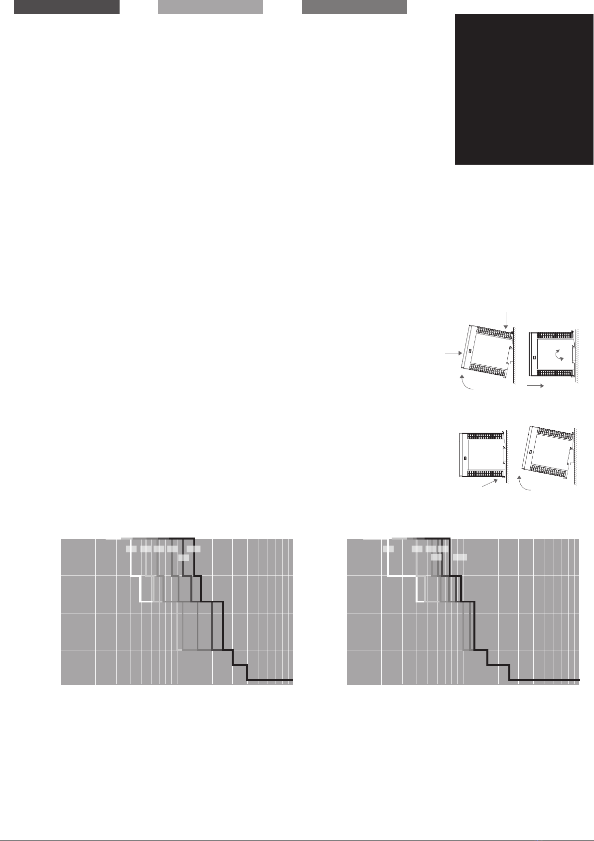
Befestigung auf Normprofilschiene
DIN EN 60715-TH35-15/ 7,5
Mounting on standard rail
DIN EN 60715-TH35-15/ 7,5
Montage sur rail
DIN EN 60715-TH35-15/ 7,5
√
Gewicht Weight Poids 0,2 kg
Maße (B x H x T)
Tiefe ab Oberkante TH35 inkl. Federleisten
Dimensions (W x H x D)
depth wit hout TH35, bu t incl. terminals
Dimensions (L x H x P) ;
prof ondeur sans TH35, mais avec bornes
45 x 90 x 115,5 mm
Bestellnummern Order numbers Références produit
Bestellnummer Order number Référence produit 4 channel: 787-1664
2 channel: 787-1662
4 channel: 787-1664/0106-0000
2 channel: 787-1662/0106-0000
Technische Daten Technical data Données techniques
Sicherungskennlinie
Tripping characteristic
Caractéristique du disjoncteur
Fig. 4a
I
II
III
IV
V
Fig. 4b
II
I
deutsch english français
Der elektronische Schutzschalter ist
mit drei Signal- bzw. Steuerkontakten
ausgestattet.
Über den Steuereingang S1 und den
Signalausgang S2 lassen sich sowohl
betriebsrelevante Informationen aus dem
Schutzschalter digital auslesen als auch
gezielt einzelne Ausgangskanäle ein- oder
ausschalten. Ein Reset von allen ausge-
lösten Ausgängen ist ebenfalls möglich,
sofern für mindestens 0,5 Sekunden 24
V an den Steuereingang S1 eingespeist
wird.
Mittels einer übergeordneten Steue-
rung (z.B. SPS) kann über ein codiertes
Bitmuster (Manchester-Code nach IEEE
802.3) an den Steuereingang S1 und
den Signalausgang S2 der Zustand der
Ausgänge des Schutzschalters gesteuert
und ausgele sen werden, siehe auch die
detaillierte Beschreibung im Handbuch.
Der Signalausgang S3 dient als aktive
24 V Sammelmeldung und signalisiert
das Abschalten mindestens eines Kanals
aufgrund eines Überstroms.
The electronic circuit breaker is equipped
with three signal contacts.
Each output can be switched on and swit-
ched of f (send bit streaming - Manches-
ter-Code in acc. with IEEE 802.3) by using
the remote signal-input S1. This signal
input S1 provides also the possibility
to reset of tripped outputs by placing a
defined signal at the input. It is possible
to read out the state of each output
by using the signal output S2 (read bit
streaming - Manchester-Code in acc.
with IEEE 802.3).
The signal output S3 works as active-
high 24 V summation message. If mini-
mum one output is tripped, the state of
this output will change from 0 V to 24 V.
Le disjoncteur électronique dispose d‘une
commande et de deux signalisations.
L‘entrée de commande S1 ainsi que la
sortie de signalisation S2 permettent de
visualiser en numérique les informations
relatives au fonctionnement du
disjoncteur ainsi que de désactiver
individuellement des canaux de sortie
ciblés. Une réinitialisation de toutes
les sorties déclenchées est possible en
appliquant une tension de 24V à l’entrée
S1 pendant au moins 0,5 seconde.
Au moyen d’un dispositif de commande
supérieur (par exemple une interface
API) il est possible via une configuration
binaire codée (se reporter au code
Manchester conformément à IEE
802.3), de commander et visualiser à
l‘entrée de commande S1 et à la sortie
de signalisation S2, l‘état des sorties du
disjoncteur (se reporter à la description
détaillée du manuel).
La sortie de signalisation S3 sert de
message collectif 24 V et signale la
désactivation d‘au minimum 1 canal en
raison d‘une surintensité de courant.
Signalisierungs- und
Steuerkontakte S1/S2/S3
Signal- and control
contacts S1/S2/S3
Commande S1 et sorties de
signalisation S2/S3 T
Hinweis:
Eine detaillierte Beschreibung finden Sie im
Handbuch des Schutzschalters, das auf der
Produktseite unter www.wago.com/epsitron
kostenlos zum Download bereitsteht.
Notice:
You can download the complete manual with
detailed description from our product site under
www.wago.com/epsitron.
Indication:
Vous trouverez une description détaillée dans
le manuel du disjoncteur de protection que vous
pouvez télécharger gratuitement sur la page
produit à l‘adresse www.wago.com/epsitron
Mounting
Fig. 4a
AUF TRAGSCHIENE AUFRASTEN
I) Gerätevorderseite leicht nach oben
drehen
II) Auf Hutschiene aufsetzen
III) Bis zum Anschlag nach unten
schieben
IV) Unten gegen die Befestigungsebene
drücken (klick)
V) Leicht am Gerät rütteln, um Verrie-
gelung zu prüfen
Fig. 4b
DEMONTAGE VON TRAGSCHIENE
I) Verriegelungslasche mit Schrauben-
dreher nach unt en ziehen und öf fnen.
II) Gerät aus Tragschiene aushängen.
Montage
Fig. 4a
SNAP ON SUPPORT RAIL
I) Tilt the unit slightly rearwards
II) Fit the unit over top hat rail
III) Slide it downward until it hits the stop
IV) Press against the bottom front side
for locking (click)
V) Shake the unit slightly to check the
locking action
Fig. 4b
REMOVAL FROM DIN RAIL
I) Locking tab with a screwdriver and
pull down t o open.
II) Unhook the device from DIN rail.
Montage
Fig. 4a
POUR FIXER LE MODULE SUR LE RAIL
I) Pencher légèrement le module vers
l‘arrière
II) Placer le module sur le bord supérieur
du rail.
III) Encliqueter le module vers le bas
jusqu‘à l‘arrêt.
IV) Afin de verrouiller le module, pousser
sur la partie inférieure (clic)
V) Vérifier l‘enclenchement en secouant
légerement le module.
Fig. 4b
DEMONTAGE DU RAIL
I) Tirer le dispositif de verrouillage à
l‘aide d‘un tournevis vers le bas
pour ouvrir.
I I ) D é c r o c h e r l ‘ a p p a r e i l d u r a i l D I N .
1 10
10
100
1000
10000
100000
100
Auslösezeit (ms)
Tripping time (ms)
Temps de déclenchement (ms)
ü
Ausgangsstrom (A)
Output current (A)
Courant de sortie (A)
ü
1 A 2 A 3 A
4 A
5 A
6 A
787-1664/0106-0000
787-1662/0106-0000
1 10
10
100
1000
10000
100000
100
Auslösezeit (ms)
Tripping time (ms)
Temps de déclenchement (ms)
ü
Ausgangsstrom (A)
Output current (A)
Courant de sortie (A)
ü
2 A 3 A 4 A 6 A
8 A
10 A
787-1664
787-1662
WAGO Kontakttechnik GmbH & Co. KG
Hansastr. 27
32423 Minden
Germany
Phone: +49 571-887-0
Fax: +49 571-887-169
[email protected]
www.wago.com
Technische Änderungen vorbehalten.
Subject to change.
Sous réserve de modifications techniques.

This manual suits for next models

3

Other WAGO Circuit Breaker manuals

WAGO 787-1668/0000-0080 User manual

WAGO

WAGO 787-1668/0000-0080 User manual

WAGO EPSITRON ECB 787-1664/0000-0011 User manual

WAGO

WAGO EPSITRON ECB 787-1664/0000-0011 User manual

WAGO 787-2861 Series User manual

WAGO

WAGO 787-2861 Series User manual

WAGO EPSITRON 787-1668 Series User manual

WAGO

WAGO EPSITRON 787-1668 Series User manual

WAGO EPSITRON ECB 787-1668/0106-0054 User manual

WAGO

WAGO EPSITRON ECB 787-1668/0106-0054 User manual

Popular Circuit Breaker manuals by other brands

Circutor RECmax-CVM series instruction manual

Circutor

Circutor RECmax-CVM series instruction manual

ABB Emax manual

ABB

ABB Emax manual

Eaton DILMS80 Series Instruction leaflet

Eaton

Eaton DILMS80 Series Instruction leaflet

Eaton Series NRX user manual

Eaton

Eaton Series NRX user manual

ABB VD4 Series product manual

ABB

ABB VD4 Series product manual

Siemens GMI Series Installation operation & maintenance

Siemens

Siemens GMI Series Installation operation & maintenance

Huayi LW36A-126 operation instruction

Huayi

Huayi LW36A-126 operation instruction

ABB SACE Tmax XT quick start guide

ABB

ABB SACE Tmax XT quick start guide

Rockwell Automation Allen-Bradley 140M-C-TRE installation instructions

Rockwell Automation

Rockwell Automation Allen-Bradley 140M-C-TRE installation instructions

Leviton 46596 Installation

Leviton

Leviton 46596 Installation

LOVATO ELECTRIC SRATH21 installation manual

LOVATO ELECTRIC

LOVATO ELECTRIC SRATH21 installation manual

Schrack MC1-XD installation instructions

Schrack

Schrack MC1-XD installation instructions

CHINT YBLX-K3 Mounting instructions

CHINT

CHINT YBLX-K3 Mounting instructions

ABB VBF Series Instruction for Installation, Service and Maintenance

ABB

ABB VBF Series Instruction for Installation, Service and Maintenance

Eaton AGM2-10-PKZ0 Instruction leaflet

Eaton

Eaton AGM2-10-PKZ0 Instruction leaflet

Allen-Bradley 140U Instruction leaflet

Allen-Bradley

Allen-Bradley 140U Instruction leaflet

Malmbergs MB-2169869 instruction manual

Malmbergs

Malmbergs MB-2169869 instruction manual

National Instruments IMAQ 6822 BNC installation guide

National Instruments

National Instruments IMAQ 6822 BNC installation guide

manuals.online logo
manuals.online logoBrands
  • About & Mission
  • Contact us
  • Privacy Policy
  • Terms and Conditions

Copyright 2025 Manuals.Online. All Rights Reserved.