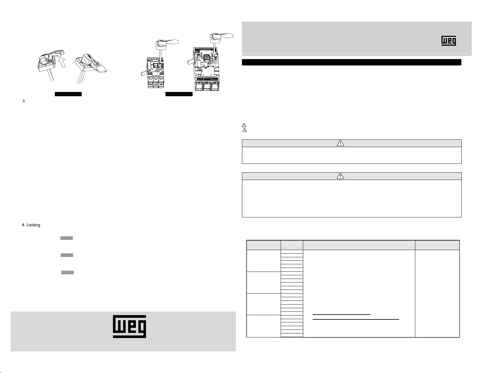
manuals.online logo
Brands
  1. Home
  2. •
  3. Brands
  4. •
  5. WEG
  6. •
  7. Circuit Breaker
  8. •
  9. WEG EHU ACW400 User manual

WEG EHU ACW400 User manual

This manual suits for next models

3

Other WEG Circuit Breaker manuals

WEG AGW650+MRXL User manual

WEG

WEG AGW650+MRXL User manual

WEG ACW400 User manual

WEG

WEG ACW400 User manual

WEG AGW650 User manual

WEG

WEG AGW650 User manual

WEG FHU ACW800 User manual

WEG

WEG FHU ACW800 User manual

WEG DWB800 User manual

WEG

WEG DWB800 User manual

WEG CESTARI Worm Gearbox line User manual

WEG

WEG CESTARI Worm Gearbox line User manual

WEG UBW225 User manual

WEG

WEG UBW225 User manual

WEG DW-161 User manual

WEG

WEG DW-161 User manual

WEG CWB40 80 Series User manual

WEG

WEG CWB40 80 Series User manual

WEG ABW Series User manual

WEG

WEG ABW Series User manual

WEG DWB100 User manual

WEG

WEG DWB100 User manual

WEG ACW100 User manual

WEG

WEG ACW100 User manual

WEG MRX ACW100 User manual

WEG

WEG MRX ACW100 User manual

WEG DWB600 User manual

WEG

WEG DWB600 User manual

WEG DWA 630 User manual

WEG

WEG DWA 630 User manual

WEG UBW2500 User manual

WEG

WEG UBW2500 User manual

WEG MPW25 User manual

WEG

WEG MPW25 User manual

WEG ACW Series User manual

WEG

WEG ACW Series User manual

WEG FHU ACW125 User manual

WEG

WEG FHU ACW125 User manual

WEG VBWC Series Manual

WEG

WEG VBWC Series Manual

WEG UBW800S User manual

WEG

WEG UBW800S User manual

WEG SSW900-CRS485-W User manual

WEG

WEG SSW900-CRS485-W User manual

WEG AM DWA400 User manual

WEG

WEG AM DWA400 User manual

WEG UBW250 User manual

WEG

WEG UBW250 User manual

Popular Circuit Breaker manuals by other brands

Siemens 3VT9524-4TG30 quick start guide

Siemens

Siemens 3VT9524-4TG30 quick start guide

Acrel ASCB1 Series Installation and operation manual

Acrel

Acrel ASCB1 Series Installation and operation manual

ABB SACE Emax 2 E2.2 manual

ABB

ABB SACE Emax 2 E2.2 manual

Eaton NOVA LBS 15 Installation and operation instructions

Eaton

Eaton NOVA LBS 15 Installation and operation instructions

ABB SACE Emax E1 quick start guide

ABB

ABB SACE Emax E1 quick start guide

Siemens SIRIUS 3RV1742 Original operating instructions

Siemens

Siemens SIRIUS 3RV1742 Original operating instructions

TERASAKI NHP TemBreak PRO P160 Series installation instructions

TERASAKI

TERASAKI NHP TemBreak PRO P160 Series installation instructions

Siemens Sentron 3VA9157-0PK1 Series operating instructions

Siemens

Siemens Sentron 3VA9157-0PK1 Series operating instructions

hager TS 303 User instruction

hager

hager TS 303 User instruction

ETI EFI-4B Instructions for mounting

ETI

ETI EFI-4B Instructions for mounting

Gladiator GCB150 Installation instruction

Gladiator

Gladiator GCB150 Installation instruction

nader NDM3EU-225 operating instructions

nader

nader NDM3EU-225 operating instructions

Eaton 50DHP-VR Instruction handbook

Eaton

Eaton 50DHP-VR Instruction handbook

ABB SACE Emax 2 E6.2 Instruction handbook

ABB

ABB SACE Emax 2 E6.2 Instruction handbook

Gewiss 90 RCD Installation

Gewiss

Gewiss 90 RCD Installation

OEZ LFN Instructions for use

OEZ

OEZ LFN Instructions for use

Eaton Power Defense PDG2 Instruction leaflet

Eaton

Eaton Power Defense PDG2 Instruction leaflet

Bticino L4412CM2 quick start guide

Bticino

Bticino L4412CM2 quick start guide

manuals.online logo
manuals.online logoBrands
  • About & Mission
  • Contact us
  • Privacy Policy
  • Terms and Conditions

Copyright 2025 Manuals.Online. All Rights Reserved.

ACW400 ACW800
Fig 11Fig 10
Installation Instruction
1. Check points before use
Check the packed parts described at Table 1, Fig 1 as soon as you receive them.
1.Do not use deformed or damaged MCCB or operating handle.
2.Mounting, , wiring, maintenance and checking should be done by authorized or certified personnel.
3. Operating handle should not be used in severe environment such as high temperature, humidity, dusty, corrosive gas, excessive vibration
and impuls.
4.Mounting should be done according to the instruction manual. Mistakes on mouting may be a cause for a MCCB or operating handle to
cause an accident such as operator injury .
withdrawing
himself
DANGER
CAUTION
Table 1. Parts list according to the handle type
*Turn off the power before mounting, withdrawing, wiring, maintenanceor inspection, Or it may be a cause for electrical shock or fire.
Read the instruction manual and safety precautions before use products.
This manual should be given to the person who use products and maintain them.
S
Before installation, wiring, operation, maintenance or inspection of the device,
Please follow the instructions, they are very important.
*In this instruction, level of dangerous are classified by 'DANGER' and 'CAUTION'.
AFETY PRECAUTIONS
be sure to read the warning message carefully and ensurance
proper operation.
ROTARY HANDLE EHU ACW400 EHU ACW800 EHX ACW400 EHX ACW800
DANGER
CAUTION It may result in death or serious injury.
It may result in injury or physical damage.
After installation, test operation before use.
1) Operation of Handle
Close the door and rotate the Handle to RESET position.
Rotate the Handle to ON and OFF positions to check operations.
It is possible that there is problem if Handle returns to TRIP or OFF positions when you try to turn the circuit breaker ON.
In this case, please go the Handle and circuit breaker to chek if they are correctly installed.
2) Opening and Closing of Panel door
Opening and closing of panel door is possible when the Handle is on 'OFF' position.
Door cannot be opened when Handle is on 'ON' position.
The SHAFT should be inserted to the groove of HANDLE ASS'Y smoothly.
Handle
automatically
Test
1) HANDLE LOCK(OFF)
Using the padlock through the hole of LOCK PLATE, HANDLE LOCK(OFF).
Operate the handle to the 'OFF' position and pull the LOCK PLATE.
2) HANDLE LOCK(ON)
Using the padlock through the hole of LOCK PLATE, HANDLE LOCK(ON).
Operate the handle to the 'ON' position and pull the LOCK PLATE.
3) BASE LOCK(OFF)
If you want to prevent circuit breaker operation, you can use the BASE LOCK(OFF).
There are aligned holes at lower left side of BASE ASS'Y at the 'OFF' position that can be used for locking
the circuit breaker in the OFF position. ײ10.
F gi10.
F gi10.
F g 1i1.
Handle has three kinds of locking.
ACW TypeHandle Appendix
Handle mounted on
Panel Door
BASE ASS'Y
assembled
on the circuit breaker
Connected with Shaft.
Parts list
1
Instruction Manual
4-4. M4 X L12 SCREW 2ea
4-5. M4 NUT 2ea
5. SUPPORTER 1ea
. BASE ASS'Y
2. SHAFT (12 inch, 16 inch, 24 inch)
3. HANDLE ASS'Y
4. SPARE PART
4-1. M4 X L22 SCREW 2ea
4-2. NO.8-32 UNC-2A, L100 (EHU ACW125~EHU ACW250) :
SCREW 4ea
NO.10-24 UNC-2A, L100 (EHU ACW400) : SCREW 4ea
1/4"-20 UNC-2A, L140 (EHU ACW800) : SCREW 4ea
4-3.
6. 1 Gasket(Neoprene 1 sheet); or
7. 2 Gasket(VFS-1G 1 sheet, Neoprene 1 sheet)
EHU 12
EHU 16
EHU 24
EHX 12
EHX 16
EHX 24
EHU 12
EHU 16
EHU 24
EHX 12
EHX 16
EHX 24
EHU 12
EHU 16
EHU 24
EHX 12
EHX 16
EHX 24
EHU 12
EHU 16
EHU 24
EHX 12
EHX 16
EHX 24
ACW125
ACW250
ACW400
ACW800
ACW400
ACW800
VFS-1R Gasket
(Red)
Neoperen Gasket
(Black)
Fig 7
Fig 4
ON
TRIP
OFF
BASE ASS'Y
SHAFT BASE
Screw(M4x22)
Supporter
Supporter
SHAFT BASE
ACW400
ACW800
ACW400 ACW800
° ±Push
Nut (M4)
Fig 3Fig 2Fig 1
® ¯A
Unblocked hole SHAFT HOLDER
(Internal element)
BACK BASE
V LEVER
(Internal element)
Fig 9
10.84 (275.4) 5.09 (129.5)
ACW400 ACW800
basing on 12 inch
4.97(126.2)
6.02(152.8)
8.12(206.2)
17.04 (432.9)
17.5 (444.6)
18.71 (475.3)
18.54 (470.8)
19 (482.5)
20.2 (513.2)
10.83 (275.12) 6.59 (167.4)
basing on 12 inch
Fig 8
9.61(244.1)
7.50(190.7)
6.46(164.1)
0.433 (11) 0.433 (11)
Mounting Screw
1.39 (35.3)
1.83 (46.5)
2.22 (56.3)
2.76 (70)
Fig 5 Fig 6
® ¯B
TAPPING
(4 Holes)
BAR PLATE
ACW400 ACW800
1) ount the support on BASE ASS'Y with two screws, M4 X L22 and nuts.
At this time, the center of support should be aligned to the center of groove in SHAFT BASE.
2) Before installation of Handle, Push the TRIP-BUTTON of the circut breaker to power it off.
Circuit breaker handle should move to the middle side (TRIP position) after pressing the BUTTON.
Fig1.
Fig2.
Fig3.
Fig4.
3) The BAR PLATE of ACW125/ACW250(EHU1,2/EHX1,2) should be at OFF position when you unpack it. First, lay the BASE
ASS'Y on the circuit breaker so that circuit breaker¯s handle projects through the hole of BAR PLATE. Then, Pull the BA
SE
ASS'Y to align mounting holes of BASE ASS'Y with circuit breaker's mounting holes. Tighten up with mounting screws pr
ovided
whith the handle.
When you want to attach the new Handle on circuit breaker already mounted, remove two of four mounting screws of circui
t
breaker and replace them with Handle mouting screws.
In this case, first remove the two screws from
circuit breaker on diagonal side, align the Handle to the right position and
thighten two Handle mounting screws to empty mounting holes.
Fig 5.
4) Assemble the HANDLE ASS'Y to the panel door.
Before assembling,
You can change operating angle, by rotating the HANDLE ASS'Y position by 90 degree at same center point in clockwise di
rection only.
In this case, please check whether the length of handle interferes with the panel opening before changing.
You may use the ~X types(ex;EHX16 ACW125) for IP65 protection such as appling to NEMA 4 panel.
This handle has two Gaskets, one for NEMA12 and the other for NEMA4.
From the surface of panel, the NEMA4 gasket (Neoprene;BLACK) should be attached first, following by the other gasket
before
assembling the HANDLE ASS'Y.
drill holes in the cover as shown on Fig. 6. Use two M4xL22 screws to secure the handle. Tighten to 7lb.in (0.8N.m)
Fig 7.
Fig 8.
Fig 9.
5) if the length of shaft doesn't fit on your panel, .
Cutting should be done on side that is not connect to the HANDLE ASS'Y.
Connect the Shaft after cutting and check if the door can be opened when the HANDLE is in the 'OFF' position.
Tighten the screw M5 X L14 located at the SHAFT BASE to secure the shaft.
The SHAFT should be inserted to the handle as shown.
You can cut the shaft
2.Assembly procedures