WEG DeviceNet CFW500 Instructions for use

Motors | Automation | Energy | Transmission & Distribution | Coatings
SOLAR PUMP DRIVE
CFW500
Application Manual
Language: English
Document: 10005553220 / 00

Application Manual
Solar Pump Drive
Series: CFW500
Language: English
Document Number: 10005553220 / 00
Publication Date: 02/2018

Contents
Solar Pump Drive | 3
CONTENTS
ABOUT THE MANUAL.................................................................................. 4
ABBREVIATIONS AND DEFINITIONS..........................................................................................................4
NUMERICAL REPRESENTATION ................................................................................................................4
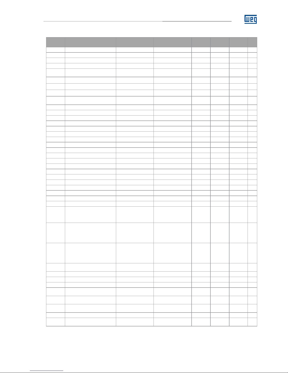
QUICK PARAMETER REFERENCE ............................................................. 5
FAULTS AND ALARMS ................................................................................ 7
1 SAFETY INSTRUCTIONS .......................................................................... 8
1.1 SAFETY WARNINGS IN THIS MANUAL ................................................................................................8
1.2 SAFETY WARNING IN THE PRODUCT .................................................................................................8
1.3 PRELIMINARY RECOMMENDATIONS..................................................................................................8
2 PHOTOVOLTAIC WATER PUMPING SYSTEM ...................................... 10
2.1 OVERVIEW OF THE CFW500 IN PHOTOVOLTAIC SYSTEMS...........................................................10
2.2 GENERAL CHARACTERISTICS OF THE SOLAR PUMP....................................................................10
3 INSTALLATION ........................................................................................ 12
3.1 SIZING OF PHOTOVOLTAICS SOLAR MODULES .............................................................................12
3.2 CONNECTIONS .....................................................................................................................................13
3.2.1 Frame A
.........................................................................................................................................................14
3.2.2 Frames B, C, D and E
................................................................................................................................15
3.2.3 Frames B, C, D and E with Hybrid Power
............................................................................................16
4 CONTROL METHOD BY MAXIMUM POWER POINT TRACKING......... 17
5 PARAMETERS DESCRIPTION................................................................ 18
5.1 VOLTAGE REGULATOR .......................................................................................................................18
5.1.1 Photovoltaic Generator Data
...................................................................................................................18
5.1.2 Voltage Setpoint Limits
.............................................................................................................................19
5.1.3 Voltage PID Controller
..............................................................................................................................19
5.1.4 System Start Configuration
.....................................................................................................................20
5.1.5 Solar Weg Detector
...................................................................................................................................21
5.2 PRESSURE CONTROLLER ..................................................................................................................22
5.2.1 Pressure PID Controller
............................................................................................................................22
5.2.2 Sleep Mode
..................................................................................................................................................23
5.3 PROTECTIONS ......................................................................................................................................24
5.3.1 Dry Pump
......................................................................................................................................................24
5.3.2 Minimum Output Pressure
.......................................................................................................................25
5.3.3 Maximum Output Pressure
......................................................................................................................25
5.4 CONTROL SETPOINT ...........................................................................................................................26
5.4.1 Reset of P1014 and P1015
.......................................................................................................................26
5.5 HMI MONITORING ................................................................................................................................27
5.6 READING PARAMETERS .....................................................................................................................27
6 POWER UP AND START UP ................................................................... 29

About the Manual
Solar Pump Drive | 4
ABOUT THE MANUAL
This manual provides the necessary information for the configuration of Solar Pump Drive application developed
with the CFW500 inverter SoftPLC function. This application manual must be used together with the CFW500
user’s manual, the SoftPLC function manual and the WLP software manual.
ABBREVIATIONS AND DEFINITIONS
PLC Programmable Logic Controller
CRC Cycling Redundancy Check
RAM Random Access Memory
USB Universal Serial Bus
WLP Ladder Language Programming Software
NUMERICAL REPRESENTATION
Decimal numbers are represented by means of digits without suffix. Hexadecimal numbers are represented with
the letter 'h' after the number.

Quick Parameter Reference, Faults and Alarms
Solar Pump Drive | 5
QUICK PARAMETER REFERENCE
Parameter
Description Adjustable Range Factory Setting User
Setting Properties
Groups
Page
P0100
Acceleration Time
0.1 to 999.0 s
5.0 s
BASIC
-
P0101
Deceleration Time
0.1 to 999.0 s
5.0 s
BASIC
-
P0133
Minimum Speed
0.0 to 500.0 Hz
30.0 Hz
BASIC
-
P0134
Maximum Speed
0.0 to 500.0 Hz
50.0 Hz
BASIC
-
P0136
Manual Torque Boost
0.0 to 30.0%
According to
inverter model
V/F
MOTOR,
BASIC
-
P0142
Maximum Output Voltage
0.0 to 100.0 %
100.0 %
cfg V/F
-
P0143
Intermediate Output Voltage
0.0 to 100.0 %
66.7 %
cfg V/F
-
P0144
Minimum Output Voltage
0.0 to 100.0 %
33,3 %
cfg V/F
-
P0202
Type of Control
0 to 5
0 = V/F
cfg
STARTUP
-
P0203
Special Function Sel.
0 to 3
0 = None
cfg
-
P0204
Load/Save Parameters
0 to 10
0 = Not Used
cfg
-
P0205
Main Display Parameter
0 to 1500
4
HMI
-
P0206
Secondary Display Parameter
0 to 1500
5
HMI
-
P0207
Parameter for Bar
0 to 1500
3
HMI
-
P0209
Ref. Eng. Unit
0 to 19
13 = Hertz (Hz)
HMI
-
P0216
HMI Backlight
0 to 1
0 = Off
cfg
HMI
-
P0220
LOC/REM Selection Source
0 to 11
1 = Always Remote
cfg
SPLC
-
P0222
REM Reference Sel.
0 to 17
12 = SoftPLC
cfg
SPLC
-
P0226
REM Rotation Selection
0 to 12 0 = Clockwise cfg
SPLC
-
P0227
REM Run/Stop Selection
0 to 5 5 = SoftPLC cfg
SPLC
-
P0228
REM JOG Selection
0 to 6 0 = Disable cfg
SPLC
-
P0230
Dead Zone (AIs)
0 to 1
1 = Active
cfg
SPLC
-
P0231
AI1 Signal Function
0 to 15
1 = Not Used
SPLC
-
P0233
AI1 Input Signal
0 to 3
1 = 4 to 20 mA
SPLC
-
P0235
AI1 Input Filter
0.00 to 16,00 0,30
SPLC
-
P0236
AI2 Signal Function
0 to 15 1 = Not Used
cfg
SPLC
-
P0238
AI2 Input Signal
0 to 3 0 = 0 to 10 V
cfg
SPLC
-
P0263
DI1 Input Function
0 to 46 1 = Run / Stop cfg
SPLC
-
P0264
DI2 Input Function
0 to 46
40 = Pressure Control
42 =
Power by Group or
Network
40 = Pressure Control
cfg
SPLC
-
P0265
DI3 Input Function
0 to 46
41 = 1st DI for Control
Setpoint Selection
42 =
Power by Group or
Network
41 = 1st DI for Control
Setpoint Selection
cfg
SPLC
-
P0266
DI4 Input Function
0 to 46
41 = 2nd DI for Control
Setpoint Selection
42 =
Power by Group or
Network
41 = 2nd DI for Control
Setpoint Selection
cfg
SPLC
-
P0275
DO1 Output Function
37 = Triggers External
Power
11 = Run
SPLC
-
P0320
Flying Start/Ride-Through
0 to 3 3 = Ride-Through cfg
SPLC
-
P0331
Voltage Ramp
0.2 to 60.0 s 10.0 s
SPLC
-
P0340
Auto-Reset Time
0 to 255 s 255 s
SPLC
-
P0400
Motor Rated Voltage
200 to 600 V
According to
inverter model cfg VVW
SPLC
-
P0401
Motor Rated Current
0.0 to 200.0 A
According to
inverter model
cfg
SPLC
-
P0402
Motor Rated Speed
0 to 30000 rpm
According to
inverter model
cfg
SPLC
-
P0403
Motor Rated Frequency
0 to 500.0 Hz 50.0 Hz
cfg
SPLC
-
P0510
SoftPLC Eng. Unit 1
0 = None
13 = Hz
13 = Hz
HMI, SPLC
-

Quick Parameter Reference, Faults and Alarms
Solar Pump Drive | 6
Parameter
Description Adjustable Range Factory
Setting
User
Setting
Properties
Groups Pag
e
P1010
Solar Pump Drive Application Version
0.00 to 10.00
ro
SPLC
21
P1011
Current Tracking Setpoint
0 to 1000 V
ro
SPLC
21
P1012
Actual Pression Setpoint / Speed
0.0 to 300.0 [Eng. Un.1]
ro
SPLC
22
P1013
Output Pressure
0.0 to 300.0
ro
SPLC
22
P1014
Operating Time CFW500
0 to 65535 h
ro
SPLC
22
P1015
Counter kWh
0 to 65535 kWh
ro
SPLC
22
P1019
Increment Rate MPPT
1 to 20
5
SPLC
22
P1020
Maximum Power Voltage (Vmpp)
0 to 1000 V
185 V
SPLC
23
P1021
Open Circuit Voltage (Voc)
0 to 1000 V
45 V
SPLC
23
P1022
Minimum Setpoint Vdc
0 to 1000 V
167 V
SPLC
23
P1023
Maximum Setpoint Vdc
0 to 1000 V
204 V
SPLC
23
P1024
PID Proportional Gain Vdc
0.000 to 32.000
1.000
SPLC
24
P1025
PID Integral Gain Vdc
0.00 to 32.00
20.00
SPLC
24
P1026
PID Integral Gain Vdc
0.000 to 32.000
0.00
SPLC
24
P1027
Starting Time
0 to 30000 s
15 s
SPLC
24
P1028
Starting Value of AI2
0.0 to 100.0 %
0.0 %
SPLC
25
P1029
Actuation Value DOx
0.0 to 100.0 %
0.0 %
SPLC
25
P1030
Pressure Control
0 = Disabled
1 = Enabled
2 = Enabled via DI2
0
SPLC
25
P1031
Pressure Sensor Scale
0.0 to 300.0 10.0
SPLC
25
P1032
PID Proportional Gain Pressure
0.000 to 32.000
1.000
SPLC
20
P1033
PID Integral Gain Pressure
0.00 to 320.00
10.00
SPLC
26
P1034
PID Integral Gain Pressure
0.000 to 32.000
0.000
SPLC
26
P1035
Pump Motor Speed below which
Solar Pump Drive goes to Sleep
Mode
0.0 to 300.0 Hz 0.0 Hz
SPLC
26
P1036
Time Delay for Solar Pump Drive goes
to Sleep Mode
1 to 65000 s
10 s
SPLC
26
P1037
Control Process Variable Deviation for
Solar Pump Drive to Wake Up
0.0 to 300.0 0.0
SPLC
26
P1038
Vdc Start Level
0 to 1000 V 0 V
SPLC
21
P1040
Time Delay for Dry Pump Fault (F781)
0 to 65000 s
0 s
SPLC
21
P1041
Motor Speed for Dry Pump
0.0 to 300.0 Hz
49.0 Hz
SPLC
22
P1042
Motor Torque for Dry Pump
0.1 to 100.0 %
20.0 %
SPLC
22
P1043
Time Reset Fault for Dry Pump
0 to 6500 min
0 min
SPLC
22
P1044
Minimum Output Pressure
0.0 to 300.0
0.0
SPLC
22
P1045
Minimum Fault Pressure Time
0 to 65000 s 0 s
SPLC
22
P1046
Maximum Output Pressure
0.0 to 300.0
0.0
SPLC
23
P1047
Maximum Fault Pressure Time
0 to 65000 s 0 s
SPLC
23
P1049
Actuation Time DOx
0 to 65000 s
0 s
SPLC
23
P1051
Control Setpoint 1
0.0 to 300.0 [Eng. Un.1] 60.0
SPLC
23
P1052
Control Setpoint 2
0.0 to 300.0 [Eng. Un.1] 1.5
SPLC
24
P1053
Control Setpoint 3
0.0 to 300.0 [Eng. Un.1]
1.5
SPLC
24
P1054
Control Setpoint 4
0.0 to 300.0 [Eng. Un.1]
1.5
SPLC
24
P1059
Operation (P1014) time and kWh
(P1015) Reset
0 = Not Used
1 = Resets Time Counter
2 = Reset kWh
0
SPLC
24

Quick Parameter Reference, Faults and Alarms
Solar Pump Drive | 7
FAULTS AND ALARMS
Fault / Alarm Description Possible Causes
F021:
Undervoltage on the DC Link
Undervoltage fault on the intermediate
circuit.
Wrong voltage supply; check if the data on the
inverter label comply with the power supply and
parameter P0296.
„Supply voltage too low, producing voltage on the
DC Link below the minimum value (in P0004):
Ud < 200 Vdc in 200-240 Vac (P0296 = 0).
Ud < 360 Vdc in 380-480 Vac (P0296 = 1).
Ud < 500 Vdc in 500-600 Vac (P0296 = 2).
Phase fault in the input.
„Fault in the pre-charge circuit.
A750:
Sleep Mode Active
It indicates that the Solar Pump Drive is in the
sleep mode
Value of the pump motor speed is below the
threshold programmed in P1035 during the time
programmed in P1036
A752:
Starting Time
It indicates that the time between start
attempts has elapsed
Starting Time was due to lack of Solar Drive
power
F761:
Minimum Pressure
Minimum system pressure failure
The system pressure is below the value of P1044
for the time programmed in P1045
F763:
Maximum Pressure
Maximum system pressure failure
The system pressure is above the value of P1046
for the time programmed in P1047
F781:
Dry Pump
It indicates that the pump was stopped due
to dry pump protection
During a time (P1040) the value of the pump
motor speed
remains above of the threshold
programmed in P1041 and motor torque remains
below the threshold programmed in P1042

Safety Instructions
Solar Pump Drive | 8
1 SAFETY INSTRUCTIONS
This manual contains the information necessary for the correct use of the frequency inverter CFW500 applied to
photovoltaic systems for water pumping.
It was developed to be operated by people with proper technical training or qualification to handle this kind of
equipment.
1.1 SAFETY WARNINGS IN THIS MANUAL
DANGER!
The procedures recommended in this warning aim at protecting the user against death, serious
injuries and considerable material damages.
ATTENTION!
The procedures recommended in this warning aim at preventing material damages.
NOTE!
The information mentioned in this warning is important for the proper understanding and good
operation of the product.
ATTENTION!
The voltage Voc should not be higher than 410V for equipments with nominal voltage 200 –
240 Vac and 810 V for equipments with nominal voltage 380 – 480 Vac to avoid damaging the
frequency inverter.
1.2 SAFETY WARNING IN THE PRODUCT
The following symbols are attached to the products as a safety warning:
High voltages presente.
Components sensitive to electrostatic discharges. Do not touch them.
Connection of the shield to the grounding.
1.3 PRELIMINARY RECOMMENDATIONS
DANGER!
Only persons with adequate technical training or qualification to operate this type of equipment.
These people should follow the safety instructions defined by a local regulations. Failure to
follow the safety instructions could result in death and/or equipment damage.

Safety Instructions
Solar Pump Drive | 9
NOTE!
For the purposes of this manual, qualified persons are those trained and are therefore suitable
for:
1. Install, ground, energize and operate the CFW500 in accordance with these manual and
legal safety procedures.
2. Wear protective equipment in accordance with established local standards.
3. Provide first aid.
DANGER!
Always open switch Q1 to disconnect the DC side of photovoltaic modules, before touching any
electrical components connected to the product. Wait for at
least ten minutes in order to
guarantee the full discharge of the capacitors. Always connect the grounding point of the
inverter to the protection grounding.
ATTENTION!
The electronic cards have components sensitive to electrostatic discharges. Do not touch the
components or connectors directly. If necessary, first touch the grounding point of the inverter
which must be connected to the protection ground or use a proper grounding strap
NOTE!
Read this manual thoroughly before installing or connecting the CFW500.

Photovoltaic Water Pumping System
Solar Pump Drive | 10
2 PHOTOVOLTAIC WATER PUMPING SYSTEM
This document presents information necessary to configure all the functions of the frequency inverter CFW500.
Applied to photovoltaic water pumping systems. For more detailed information on the function of expansion and
communications accessories, refer to the following manuals:
■ CFW500 Frequency Inverter Documentation;
■ CFW500 SoftPLC Manual;
■ CFW500 Programming Manual;
■ CFW500-CRS485 - Plug-in Module Input/Output.
These file are available on the WEG’s website - www.weg.net.
2.1 OVERVIEW OF THE CFW500 IN PHOTOVOLTAIC SYSTEMS
The frequency inverter CFW500 is a high-performance converter AC/DC and AC/DC that allows a speed and
torque control of induction three-phase motors. The frequency inverter CFW500 also features PLC (Programmable
Logic Controller) through the SoftPLC feature (integrated).
The function of the CFW500 in photovoltaic water pumping systems is to convert energy generated by
photovoltaic modules into alternating form, and to apply this energy in the activation of water pumps, according
to Figure 2.1.
Figure 2.1 – Block Diagram of a photovoltaic pumping system
Where:
(1) Solar photovoltaic plant
(2) Frequency Inverter CFW500 WEG
(3) Water pump
(4) Water tank
2.2 GENERAL CHARACTERISTICS OF THE SOLAR PUMP
The main characteristic of the Solar Pump Drive developed for the CFW500 inverter SoftPLC function is the control
of one pump using for this a frequency inverter using the power supply by a photovoltaic system, thus allowing
control of the speed of the pump.
Each is notable for the following characteristics:
■Acceleration and deceleration ramps for the pump driven by inverter;
■Maximum and minimum speed limits for the pump driven by inverter;
■ Selection the manual control mode, automatic or via digital input. If the control is in manual mode the control
setpoint will be speed, if it is in automatic the control setpoint will be pressure;
■Selection of the control setpoint via logical combination of the two digital inputs (maximum of 4 setpoints);
■Selection of the control process variable via analog input AI1;
■Selection of the engineering unit and range of the control process variable sensor via CFW500 parameters;
■Voltage setpoint Vdc minimum and maximum;
■Gain, offset and filter adjustments for the control signals via analog inputs;
■PID controller gains setting of the pressure control;
■PID controller gains setting of the voltage control;

Photovoltaic Water Pumping System
Solar Pump Drive | 11
■Enable or not of the sleep mode with the PID controller enabled;
■Wake up/Start level mode to activate the pump;
■Minimum output pressure protection;
■Maximum output pressure protection;
■Dry pump protection through evaluation of motor torque and pump speed;
■Counter hours of operation and energy produced by the solar modules and consumed by the pump.
NOTE!
For applications where the cable between motor and inverter is greater than 100 meters,
consult the WEG for sizing.

Installation
Solar Pump Drive | 12
3 INSTALLATION
3.1 SIZING OF PHOTOVOLTAICS SOLAR MODULES
To install/dimension solar photovoltaic modules must accomplish its 3 main characteristics:
■ Peak Power (Wp) Is the maximum measured power that the solar photovoltaic module establishes for the STC
condition.
■ Open Circuit Voltage (Voc) is the voltage measured at the terminals of the module when it is uncharged, for the
STC condition.
■ Maximum Power Voltage (Vmpp) is a specific value of the voltage which it is multiplied by the output current, it
will give the maximum output power, for the STC condition.
The Standard Test Conditions (STC) is the values presented were measured by standard tests under irradiation
conditions of 1000W/m² with an air mass (PM) of 1,5 and a cell temperature of 25ºC.
In the plant where such modules are installed, the climatic conditions may be different, it being necessary to
calculate a new open circuit voltage value for the scaling of the photovoltaic water pumping system. The main
factor that will affect the operation of the system will be the temperature, since the low temperatures will raise the
voltage of the open circuit (Voc).
The equation that considers all variables is complex, as well as knowing the exact values of these variables, for
this reason is presented below a simple equation that approaches the value to reality:
=()1+ ()
100
Where:
■Voc:Open circuit voltage of the photovoltaic solar module at the installation local (V);
■Np: Number of photovoltaic solar modules connected in series;
■Voc(STC):Open circuit voltage of photovoltaic solar module in STC condition;
■Tmin:Minimum operating temperature of the module at the operating local (ºC);
■T(STC): Standard panel test temperature, 25 °C;
■β: Temperature Coefficient You specified by the module data.
With this information calculates the number of solar modules that must be connected in series to operate in the
operating voltage range of the inverter. This serial connection, in turn, shall be replicated in parallel as many times
as necessary to meet the operating power of the system.
The operating voltage of the inverter varies according to the model, being 250-380Vdc for 220Vac single phase
and three phases, and 450-760Vdc for 380-440Vac models. Particular attention should be paid to the open-
circuit voltage (Voc), which should not exceed the inverter's overvoltage protection voltage. In case of voltage you
are higher, this will end up damaging the equipment.
The frequency inverters operate with undervoltage and overvoltage protection, so that if the voltage reaches these
limit values, the inverter will interrupt its operation. Table 3.1 shows the inverter operating voltage information, as
well as the overvoltage and undervoltage limits.
Table 3.1 – Voltage levels of the CFW500
CFW500
Power Supply Voltage
Monophasic
220Vac
Mon/Trif
220Vac
220Vac
Three-Phase
380
480Vac
Operating Voltage
250-380Vdc
250-380Vdc
250-380Vdc
450-760Vdc
450-760Vdc
Undervoltage Protection
200Vdc
200Vdc
200Vdc
360Vdc
360Vdc
Overvoltage Protection
410Vdc
410Vdc
410Vdc
810Vdc
810Vdc
To facilitate the understanding of sizing, we use the following system as an example:

Installation
Solar Pump Drive | 13
■CFW500 Monophasic/Three-Phase 220V;
■2CV Three-Phase Pump;
■Solar modules model GCL-P6/72 from the manufacturer GCL.
The photovoltaic solar panel model GCL-P6/72 of the manufacturer GCL has the following characteristics (STC):
Table 3.2 – Technical characteristics of the Photovoltaic Solar Module Polycrystalline
Electrical Characteristics
Nominal Power Output (Pmpp) 310 W
Voltage at Pm Point (Vmpp) 37 V
Current at Pm Point (Impp) 8,38 A
Open Circuit Voltage (Voc) 8,99 V
Short Circuit Current (Isc) 45,4 A
Module Efficiency 1,89 A
For example, is defined the serial connection of four photovoltaic solar modules , generating for the standard test
condition (STC) a maximum power voltage of 185Vdc, with an open circuit voltage (Voc) of 42,73/44,95Vdc.
By choosing to connect four solar modules in series, we are inserting power steps for the sizing of the system,
being it of 1550W. To comply with a 2CV pump it is recommended that the minimum peak power be 1471W.
The set of 5 solar modules GCL-P6/72 have the technical characteristics reported in table 3.3.
Table 3.3 – Technical information for serial connection of eight solar modules GCL-P6/72
Specific Information PV Installation (STC) 25ºC x PV Quantity
Nominal Power Output (Pmpp) 800 W
Voltage at Pm Point (Vmpp) 185 V
Current at Pm Point (Impp) 8,38 A
Open Circuit Voltage (Voc) 44,95 V
Short Circuit Current (Isc) 45,4 A
The connection of the eight solar modules must be carried out according to the diagram in figure 3.1.
Figure 3.1 – Connection of solar modules
3.2 CONNECTIONS
The type of connection to be used will be determined by the voltage of the equipment.

Installation
Solar Pump Drive | 14
3.2.1 Frame A
For inverters CFW500 and Frame "A", models without access to the DC bus terminals, the following connection
is recommended:
Figure 3.2 – Connection diagram of the water pumping photovoltaic system for inverter frame A
NOTE!
Take care to don't reverse the positive and negative voltage connections from the solar modules.
NOTE!
The inputs/outputs connections may be different from what is indicated in this diagram, depending
on the needs of the application.

Installation
Solar Pump Drive | 15
3.2.2 Frames B, C, D and E
For CFW500 frequency inverters of frames B, C, D and E, models with access to the DC bus (Ud + and Ud-) the
following connection is recommended.
Figure 3.3 – Connection diagram of the water pumping photovoltaic system for inverter
frames B, C, D and E
NOTE!
Take care to don't reverse the positive and negative voltage connections from the solar modules.
NOTE!
The inputs/outputs connections may be different from what is indicated in this diagram, depending
on the needs of the application.

Installation
Solar Pump Drive | 16
3.2.3 Frames B, C, D and E with Hybrid Power
For CFW500 frequency inverters of frames B, C, D and E, models with access to the DC bus (Ud + and Ud-) and
require hybrid power, the following connection is recommended.
Figure 3.4 – Connection diagram of the water pumping photovoltaic system for inverter
frames B, C, D and E with hybrid power
NOTE!
Take care to don't reverse the positive and negative voltage connections from the solar modules.
NOTE!
When closing the contactor K1 it must be timed to avoid that the starting peak of the generator
reaches the voltage input of the frequency inverter.
NOTE!
The inputs/outputs connections may be different from what is indicated in this diagram, depending
on the needs of the application.

Control Method by Maximum Power Point Tracking
Solar Pump Drive | 17
4 CONTROL METHOD BY MAXIMUM POWER POINT TRACKING
The strategy of control method of variable reference is constantly tracking the maximum power point of the system
(MPPT).
The maximum power point of a solar module changes according to the solar irradiance incident on the solar cell,
as well as the temperature, wind velocity, inclination of the solar photovoltaic module, passing of clouds, thus
generating the need of the constant search for maximum power of the system. Compared to the fixed-point
method, MPPT provides a higher system efficiency, which can reach 20%.
Figure 4.1 – Maximum Power Point Tracking
Where:
(1) Automatic Proportional Voltage Value at Maximum System Power
(2) Minimum Control Setpoint Level per MPPT (P1022)
(3) Maximum Control Setpoint Level per MPPT (P1023)
() Increment Rate MPPT (P1019)

Parameters Description
Solar Pump Drive | 18
5 PARAMETERS DESCRIPTION
The CFW500 inverter parameters (P0000 to P0999) and the SoftPLC function parameters (P1000 to P1059) for
the Solar Pump Drive application will be presented next.
NOTE!
The Solar Pump Drive application only works on CFW-11 inverter with
firmware higher than V2.02
.
So upgrading the CFW-11 inverter firmware to the working of this application is required.
NOTE!
The adjustable range of the CFW500 parameters has been customized for Solar Pump Drive
application. Refer to the CFW500 programming manual for more details on the parameters.
Symbols for property description:
CFG
Configuration parameter, value can be programmed only with motor stopped
RO
Read-only parameter
RW
Read and write parameter
5.1 VOLTAGE REGULATOR
This group of parameters allows the user to configure the operating conditions of the voltage regulator for
operation by the photovoltaic modules, both for direct pumping and pressure regulation.
P1019 – Increment Rate MPPT
Adjustable 1 to 20 Factory Setting: 5
Range:
Properties:
Access groups via HMI: SPLC
Description:
This parameter defines the variation rate of voltage setpoint for maximum power point tracking. Initially leave this
parameter with the defect value “5” and in case of Setpoint variation it is not fast enough to gradually increase
until the optimum operating result is achieved.
5.1.1 Photovoltaic Generator Data
P1020 – Maximum Power Point Voltage (Vmpp)
Adjustable 0 to 1000 V Factory Setting: 185 V
Range:
Properties:
Access groups via HMI: SPLC
Description:
This parameter defines the maximum power point the installed photovoltaic module system. This data will appear
on each of installed photovoltaic panels and will be named Vmpp under the STC test conditions. Thus, in the case
presented above, the value to be configured would be 185 Vdc (5 modules in series x 37 Vdc at maximum power
point).
P1021 – Open Circuit Voltage (Voc)
Adjustable 0 to 1000 V Factory Setting: 45 V
Range:
Properties:
Access groups via HMI: SPLC

Parameters Description
Solar Pump Drive | 19
Description:
This parameter defines the value of open circuit voltage of the installed PV panels. This data will appear on each
of the installed photovoltaic panels and will be named Voc under the STC test conditions. Thus, in the case
presented above, the value to configure would be 45 Vdc (5 modules in series x 8,99 Vdc of open circuit).
5.1.2 Voltage Setpoint Limits
P1022 – Minimum Setpoint Vdc
Adjustable 0 to 1000 V Factory Setting: 167 V
Range:
Properties:
Access groups via HMI: SPLC
Description:
This parameter defines the minimum value of the voltage setpoint that the system must use during the process
of maximum power point search. This parameter can start the adjustment of 10% below the maximum voltage
supply point (P1020). So, for example, we could set this value to 167 Vdc.
P1023 – Maximum Setpoint Vdc
Adjustable 0 to 1000 V Factory Setting: 204 V
Range:
Properties:
Access groups via HMI: SPLC
Description:
This parameter defines the maximum value of the voltage setpoint that the system must use during the process
of maximum power point search. This parameter can start the adjustment of 10% above the maximum voltage
supply point (P1020). So, for example, we could set this value to 204Vdc.
5.1.3 Voltage PID Controller
This group of parameters allows the user to configure the PID controller gains for the DC voltage control supplied
by the photovoltaic modules. The PID controller always will attempt to search the work point defined by Tracking
Setpoint and for this will act on the output frequency of the motor.
P1024 – Voltage PID Proportional Gain
Adjustable 0.000 to 32.000 Factory Setting: 1.000
Range:
Properties:
Access groups via HMI: SPLC
Description:
This parameter defines the proportional gain value of the PID controller for the DC voltage control.
P1025 – Voltage PID Integral Gain
Adjustable 0.00 a 320.00 Factory Setting: 20.00
Range:
Properties:
Access groups via HMI: SPLC
Description:
This parameter defines the integral gain value of the PID controller for the DC voltage control.

Parameters Description
Solar Pump Drive | 20
P1026 – Voltage PID Derivative Gain
Adjustable 0.000 to 32.000 Factory Setting: 0.000
Range:
Properties:
Access groups via HMI: SPLC
Description:
This parameter defines the derivative gain value of the PID controller for the DC voltage control.
5.1.3.1 PID Controller Gain Adjustment
In controlling pumping systems, a Proportional-Integral (PI) velocity regulator is sufficient to achieve good control
performance. The proportional gain KP(P1024) and integral KI(P1025) must be changed if the controller response
is not satisfactory, i.e. if there are oscillations in the output pressure around the setpoint, very slow response time
or constant error in relation to the setpoint. Here are some suggestions for regulator adjustment:
■ Output pressure oscillation: In most cases this is due to excessive gain of the PID controller, reduce the KPand
KIgains gradually and observe the response;
■ Very slow response time: Increasing the KPgain the system must respond faster, however from a limit the
system may have surges;
■ Constant error in the output: In this case, increasing the gain KIeliminates the constant error of the output, i.e.
when the output cannot reach the setpoint. Excessive KIgain can generate oscillations at the output, then
decrease the gain KPso that the total gain is reduced while maintaining gain KI.
5.1.4 System Start Configuration
This group of parameters allows the user to configure system start options.
NOTE!
See also parameter P1038 as a condition for starting the system autonomously.
P1027 – Time Between Starts
Adjustable 0 to 30000 s Factory Setting: 15 s
Range:
Properties:
Access groups via HMI: SPLC
Description:
This parameter defines the time between starts, when the system is stopped by power failure or when it reaches
the limit set in the parameter P1029. This delay is to avoid continuous starts and stops, and in the case of
submersible pumps, preventing the restart of the pump before the empty pipe.
Entrada DI2
NOTE!
If the run command is removed from the system, the time will be reset and once go back to operate
the run command the start will be realized immediately without consider any time.
P1049 – DO Actuation Time
Adjustable 0 to 65000 s Factory Setting: 0 s
Range:
Properties:
Access groups via HMI: SPLC
Other manuals for DeviceNet CFW500
12
Table of contents
Other WEG DC Drive manuals

WEG
WEG CFW-11 Series User manual

WEG
WEG CFW-11 Series Owner's manual

WEG
WEG CFW100 series Owner's manual

WEG
WEG CFW300 V1.3X Owner's manual

WEG
WEG CFW-11 Series User manual

WEG
WEG CFW-11 Series User manual

WEG
WEG Easy Drive CFW10 User manual

WEG
WEG MVW3000 Series User manual

WEG
WEG CFW100A01P6S220 User manual

WEG
WEG DeviceNet CFW500 User manual

WEG
WEG CFW501 User manual

WEG
WEG CFW-11 Series Owner's manual

WEG
WEG DeviceNet CFW500 User manual

WEG
WEG CFW-09 User manual

WEG
WEG bacnet CFW701 User manual

WEG
WEG CFW900 User manual

WEG
WEG CFW100 series User manual

WEG
WEG CFW-11 Series User manual

WEG
WEG MW500 series User manual

WEG
WEG CFW-11 Series User manual