manuals.online logo
Brands
  1. Home
  2. •
  3. Brands
  4. •
  5. Weinmann & Schanz
  6. •
  7. Digital Manifold
  8. •
  9. Weinmann & Schanz 671 Series Guide

Weinmann & Schanz 671 Series Guide

This manual suits for next models

1

Popular Digital Manifold manuals by other brands

Kermi x-net comfort 5/4" Operator's manual

Kermi

Kermi x-net comfort 5/4" Operator's manual

WABCO TP0223 Service information

WABCO

WABCO TP0223 Service information

Refco DIGIMON4 Installation and operating guide

Refco

Refco DIGIMON4 Installation and operating guide

TESTO 550 quick start guide

TESTO

TESTO 550 quick start guide

Dräger PAS X-plore Instructions for use

Dräger

Dräger PAS X-plore Instructions for use

Immergas ERP DIM BASE Instructions and warnings

Immergas

Immergas ERP DIM BASE Instructions and warnings

Enerpac MPFL-50V instruction sheet

Enerpac

Enerpac MPFL-50V instruction sheet

Refco DIGIMON instruction manual

Refco

Refco DIGIMON instruction manual

Fieldpiece SMAN460 Operator's manual

Fieldpiece

Fieldpiece SMAN460 Operator's manual

TESTO 550s instruction manual

TESTO

TESTO 550s instruction manual

Refco DIGIMON manual

Refco

Refco DIGIMON manual

CPS Products BLACKMAX MD100 Series owner's manual

CPS Products

CPS Products BLACKMAX MD100 Series owner's manual

CPS BlackMax MD50W owner's manual

CPS

CPS BlackMax MD50W owner's manual

Warmup WHS-M-S3-Series installation manual

Warmup

Warmup WHS-M-S3-Series installation manual

Tyco RM-1 quick start guide

Tyco

Tyco RM-1 quick start guide

Sartorius Microsart Series operating instructions

Sartorius

Sartorius Microsart Series operating instructions

Fieldpiece SMAN2 user manual

Fieldpiece

Fieldpiece SMAN2 user manual

Phenomenex Presston 1000 AH1-7033 user guide

Phenomenex

Phenomenex Presston 1000 AH1-7033 user guide

manuals.online logo
manuals.online logoBrands
  • About & Mission
  • Contact us
  • Privacy Policy
  • Terms and Conditions

Copyright 2025 Manuals.Online. All Rights Reserved.

Collettori in materiale composito specifici per impianti a pannelli radianti
Manifolds in composite specifically designed for radiant panel systems
Verteiler aus Technopolymer für Fußbodenheizungsanlagen
Collecteurs en matériau composite pour planchers chauffants/rafraîchissants
Colectores de material plástico específicos para instalaciones de suelo radiante
Colectores em material composto específicos para instalações de chão radiante
Kunststofverdeler voor vloerverwarming- en koeling
671-673 series
68344.02
1
INDICE - INDEX - INHALT - TABLE DES MATIÈRES -
ÍNDICE - ÍNDICE - INHOUD
MANUALE DI INSTALLAZIONE
E MESSA IN SERVIZIO
INSTALLATION AND
COMMISSIONING MANUAL
ANLEITUNG FÜR INSTALLATION
UND INBETRIEBNAHME
MANUEL D'INSTALLATION
ET DE MISE EN SERVICE
MANUAL DE INSTALACIÓN
Y PUESTA EN SERVICIO
MANUAL DE INSTALAÇÃO E
COLOCAÇÃO EM
FUNCIONAMENTO
HANDLEIDING VOOR
INSTALLATIE EN
INBEDRIJFSTELLING
673 SERIES
671 SERIES
Funzione -Avvertenze
Function -Instructions
Funktion -Wichtige Hinweise
Fonction -Signalisations
Función - Advertencias
Função - Advertências
Functie -Waarschuwingen
2
Gamma prodotti - Caratteristiche tecniche
Product range - Technical specifications
Produktübersicht - Technische Eigenschaften
Gamme de produits - Caractéristiques techniques
Gama de productos - Características técnicas
Gama de produtos - Características técnicas
Productassortiment - Technische specificaties
3
Componenti caratteristici
Characteristic components
Hauptkomponenten
Composants spécifiques
Componentes característicos
Karakteristieke componenten
4
Composizione confezione - Caratteristiche idrauliche
Package content - Hydraulic characteristics
Lieferumfang - Hydraulische Eigenschaften
Contenu - Caractéristiques hydrauliques
Contenido del embalaje - Características hidráulicas
Composição da embalagem - Características hidráulicas
Características hidráulicas - Composição da embalagem
Inhoud van verpakking - Hydraulische kenmerken
5
Lettura e regolazione della portata
Flow reading and adjustment
Ablesen und Regelung der Durchflussmenge
Lecture et réglage du débit
Lectura y regulación del caudal
Leitura e regulação do caudal
Aflezing en inregeling
6
Installazione
Installation
Installation
Installation
Instalación
Instalação
Installatie
7
Riempimento circuiti
Filling the circuits
Befüllen der Kreise
Remplissage des circuits
Llenado de los circuitos
Enchimento dos circuitos
Vullen van de kringen
10
Prova idraulica
Hydraulic test
Hydraulischer Test
Test hydraulique
Prueba hidráulica
Teste hidráulico
Hydraulische test
12
Messa in servizio
Commissioning
Inbetriebnahme
Mise en service
Puesta en servicio
Colocação em funcionamento
Inbedrijfstelling
13
Manutenzione
Maintenance
Wartung
Entretien
Mantenimiento
Manutenção
Onderhoud
15
Accessori - Note di sicurezza
Accessories - Safety information
Zubehör - Sicherheitshinweise
Accessoires - Consignes de sécurité
Accesorios - Notas de seguridad
Acessórios - Notas de segurança
Accessoires - Veiligheid
16
I
GB
D
F
E
P
NL
2
Funzione
Function
Funktion
Fonction
Función
Função
Functie
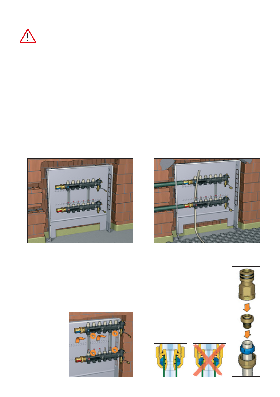
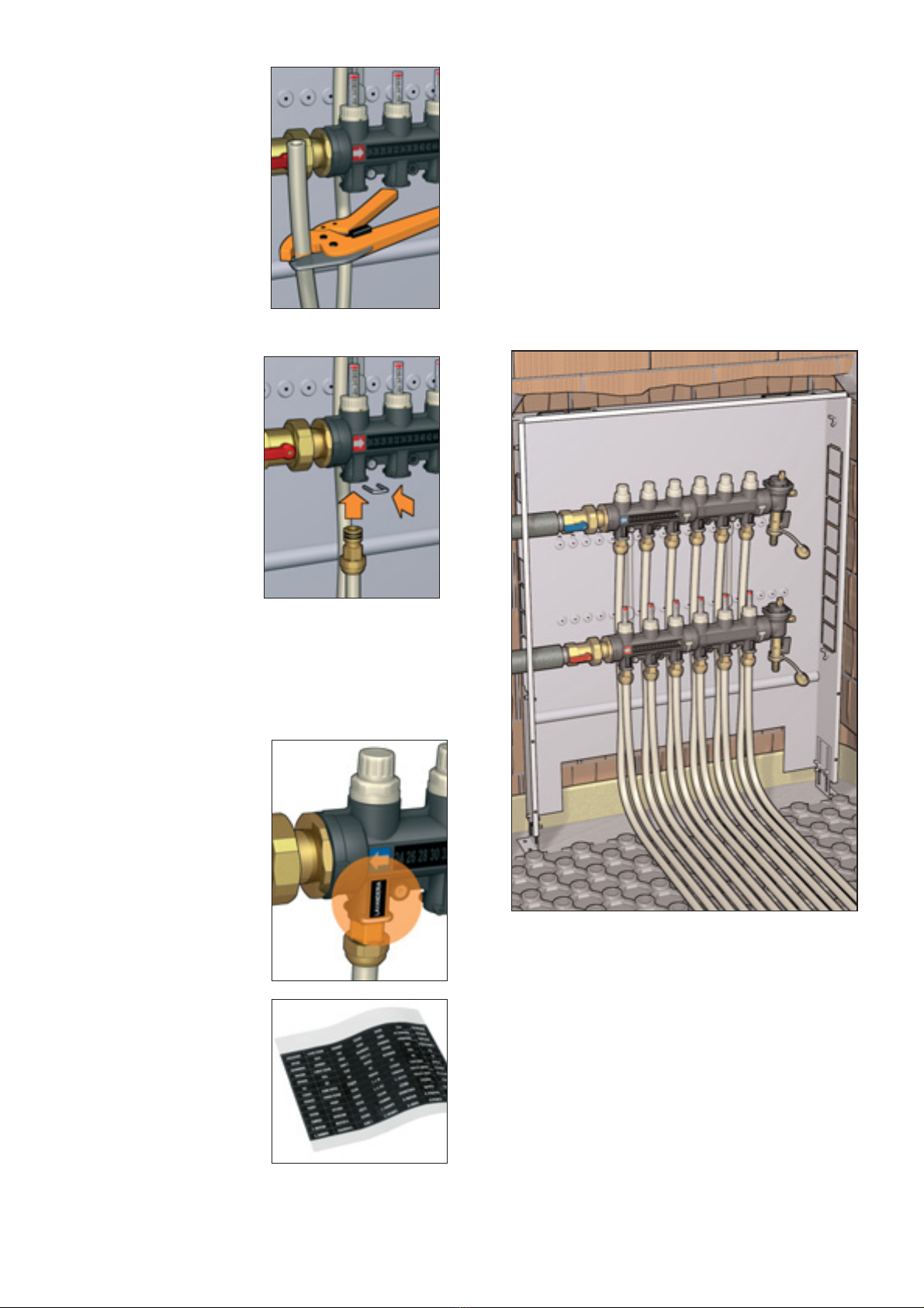
I collettori in materiale plastico vengono utilizzati per il controllo e la distribuzione del fluido nei circuiti degli impianti a pannello
radiante a pavimento. Questa particolare serie di collettori, realizzata in un materiale composito specifico per l'uso negli impianti a
bassa, temperatura, viene preassemblata in due versioni distinte secondo l'utilizzo di due differenti collettori di mandata.
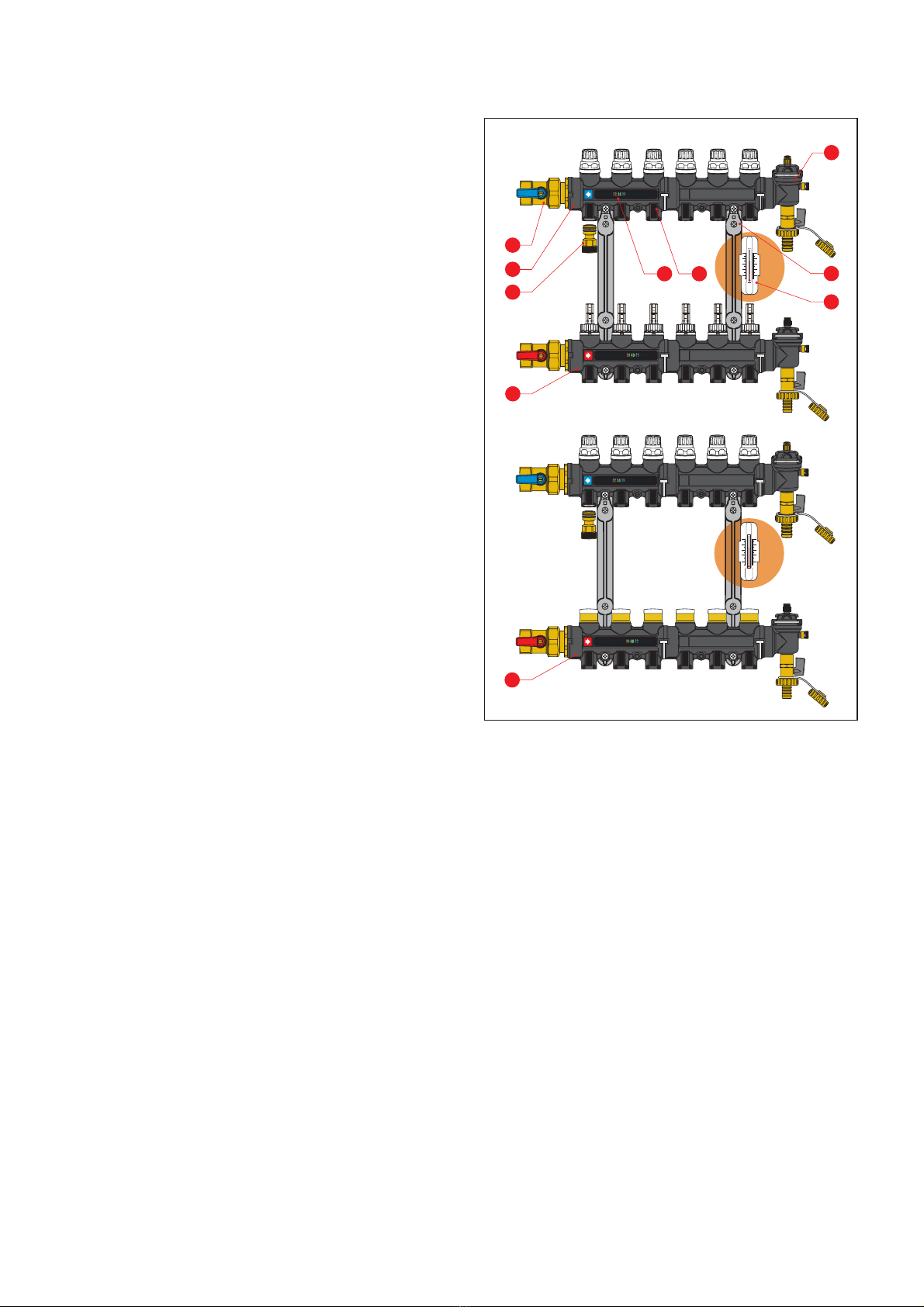
Nella prima il collettore di mandata è completo di flussometro e valvole di regolazione incorporate, nella seconda il collettore è
fornito di detentori di taratura. Gli altri componenti, comuni alle due versioni, sono rispettivamente: collettore di ritorno, completo di
valvole di intercettazione predisposte per comando elettrotermico; gruppi di testa completi di valvole automatiche di sfogo aria e
rubinetti di carico/scarico; valvole di intercettazione a sfera; termometri digitali a cristalli liquidi, sui collettori di mandata e ritorno.
The manifolds are made of plastic material and are used to control and distribute fluid to the circuits in underfloor radiant panel
systems. This particular series of distribution manifolds, made of a special plastic material designed for use in
low-temperature systems, comes pre-assembled in two different versions, which use two different flow manifolds.
In the first version, the flow distribution manifold has an built-in flow meter and control valves; in the second version, the manifold
is equipped with calibrating lockshields. The other components are common to both versions, and are as follows: return manifold
with shut-off valves pre-fitted for a thermo-electric control; end fittings with automatic air vent and filler/drain cocks; shut-off ball
valves; LCD digital thermometers on the flow and return manifolds.
Die Verteiler aus Kunststoff werden für die Kontrolle und Verteilung des Mediums in den Kreisläufen von
Fußbodenheizungsanlagen eingesetzt. Diese Verteilerserie aus speziell für Anlagen mit niedriger Temperatur geeignetem
Verbundwerkstoff wird in zwei verschiedenen Versionen je nach Verwendung zweier unterschiedlicher Vorlaufverteiler vormontiert.
In der ersten Version wird der Vorlaufverteiler komplett mit Durchflussmesser und integrierten Regelventilen geliefert, in der zweiten
Version ist der Verteiler mit voreinstellbaren Rücklaufverschraubungen ausgestattet. Die übrigen Komponenten sind für beide
Versionen identisch: Rücklaufverteiler mit Absperrventilen nachrüstbar mit elektrothermischen Stellantrieben; Kopfgruppen mit
automatischen Schnellentlüftern und KFE-Hähnen; Kugelhähne; digitale Flüssigkristallthermometer auf den Vor- und
Rücklaufverteilern.
Les collecteurs en matériau composite sont utilisés pour la distribution et la régulation des circuits des installations de plancher
chauffant/rafraîchissant. Cette série spéciale de collecteurs, réalisée en matériau composite spécifique pouvant être utilisée dans
les installations à basse température, est préassemblée en deux versions en fonction de l'utilisation de deux collecteurs départ.
Dans la première, le collecteur départ comprend un débitmètre et des vannes de réglage ; dans la deuxième, le collecteur est
doté d'organes de réglage. Les autres composants, communs aux deux versions, sont respectivement : collecteur retour, doté de
vannes d'arrêt prédisposées pour tête électrothermique; ensembles de terminaison avec purgeurs d'air et robinet
d’alimentation/vidange ; vannes d'arrêt à sphère ; thermomètres numériques à cristaux liquides, sur les collecteurs départ et retour.
Los colectores de plástico se utilizan para el control y la distribución del fluido en las instalaciones de suelo radiante. Estos
colectores están realizados con un material compuesto, específico para el uso en sistemas de baja temperatura, y se entregan
preensamblados en dos versiones para utilizar con dos colectores de ida diferentes.
Un modelo de colector de ida está equipado con caudalímetro y válvulas de regulación; el segundo, con detentores de
calibración. Los demás componentes, comunes a ambas versiones, son: colector de retorno con válvulas de corte preparadas
para mando electrotérmico, grupos de cabecera con válvulas automáticas de purga de aire y llaves de carga y descarga; válvulas
esféricas de corte y termómetros digitales de cristales líquidos.
Os colectores em material plástico são utilizados para o controlo e a distribuição do fluido nas instalações de chão radiante.
Esta particular série de colectores, realizada num material composto, específico para o uso nos sistemas de baixa temperatura,
é pré-montada em duas versões distintas conforme a utilização de dois colectores de descarga diferentes.
Na primeira, o colector de ida é dotado de fluxómetro e de válvulas de regulação incorporadas, na segunda, o colector está
equipado com detentores de calibragem. Os outros componentes, comuns às duas versões, são respectivamente: colector de
retorno, dotado de válvulas de corte preparadas para o comando electrotérmico; grupos de topo dotados de purgadores
automáticos de ar e torneiras de carga/descarga; válvulas de corte de esfera; termómetros digitais de cristais líquidos, nos
colectores de ida e retorno.
De kunststof verdeler wordt gebruikt voor het controleren en het verdelen van het medium in installaties voor vloerverwarming en
-koeling. Deze serie verdelers is gemaakt van een speciaal composiet voor gebruik in installaties met lage temperaturen. Ze
worden in twee verschillende uitvoeringen voorgemonteerd, al naargelang de toepassing van de twee verschillende
aanvoerverdelers. Bij de eerste uitvoering is de aanvoerverdeler uitgerust met een debietmeter en ingebouwde regelventielen, bij
de tweede uitvoering is de aanvoerverdeler uitgerust met geïntegreerde regelventielen. De overige componenten zijn identiek in
beide uitvoeringen: een retourverdeler met afsluiters die geschikt zijn voor elektrothermische bediening; een eindgroep met een
automatische ontluchter voorzien van een snelontluchter en een vul- en aftapkraan; kogelafsluiters; thermometers met LCD-
weergave op de aanvoer- en retourverdeler.
AVVERTENZE: Le seguenti istruzioni devono essere lette e comprese prima dell’installazione, messa in servizio e
manutenzione del collettore.
IMPORTANT: The following instructions must be read and understood before installing, starting up or maintaining
the manifold.
HINWEIS: Die folgenden Anleitungen müssen vor Installation, Inbetriebnahme und Wartung des Verteilers gelesen
und verstanden worden sein.
AVERTISSEMENTS : S'assurer d'avoir lu et compris les instructions suivantes avant de procéder à l'installation, à la mise en
service et à l'entretien du collecteur.
ADVERTENCIAS: Antes de realizar la instalación, la puesta en servicio y el mantenimiento del colector, es
indispensable leer y comprender las siguientes instrucciones.
ADVERTÊNCIAS: As instruções seguintes devem ser lidas e compreendidas antes da instalação, da colocação em
funcionamento e da manutenção do colector.
WAARSCHUWING: de onderstaande instructies moeten gelezen en begrepen zijn voordat met de installatie, de
inbedrijfstelling en het onderhoud aan de verdeler wordt gestart.
I
l simbolo di sicurezza viene usato in questo manuale per attirare l’attenzione alle istruzioni relative alla sicurezza. Il simbolo ha il seguente significato
ATTENZIONE! LA TUA SICUREZZA È COINVOLTA. UNA MANCANZA NEL SEGUIRE QUESTE ISTRUZIONI PUÒ ORIGINARE
PERICOLO.
A safety symbol is used in this manual to indicate instructions where safety is involved. The meaning of this symbol is as follows:
WARNING! FOLLOWING THESE INSTRUCTIONS IS IMPORTANT FOR YOUR SAFETY. FAILURE TO FOLLOW THEM MAY RESULT IN
PERSONAL INJURY.
Mit dem Sicherheitssymbol wird in dieser Anleitung auf Sicherheitshinweise aufmerksam gemacht. Das Symbol hat folgende Bedeutung:
ACHTUNG! ES GEHT UM IHRE SICHERHEIT. EINE MISSACHTUNG DIESER ANWEISUNGEN KANN GEFAHRENSITUATIONEN VERURSACHEN.
Le symbole de sécurité utilisé dans ce manuel sert à attirer l’attention sur les consignes de sécurité. Signification du symbole :
ATTENTION ! VOTRE SÉCURITÉ EST EN JEU. RESPECTER IMPÉRATIVEMENT LES CONSIGNES SUIVANTES POUR NE COURIR AUCUN RISQUE.
Este símbolo se utiliza en este manual para llamar la atención sobre las instrucciones relativas a la seguridad. Tiene el siguiente significado:
ATENCIÓN! SU SEGURIDAD ESTÁ EN JUEGO. EL INCUMPLIMIENTO DE ESTAS INSTRUCCIONES PUEDE SER PELIGROSO.
O símbolo de segurança é utilizado neste manual para atrair a atenção para as respectivas instruções de segurança. O símbolo tem o seguinte significado:
ATENÇÃO! A SUA SEGURANÇA ESTÁ ENVOLVIDA. O INCUMPRIMENTO DESTAS INSTRUÇÕES PODE ORIGINAR PERIGO.
In deze handleiding wordt een veiligheidssymbool gebruikt om de aandacht te vestigen op die instructies die betrekking hebben op de veiligheid. Het
symbool heeft de volgende betekenis:
LET OP! HET BETREFT UW VEILIGHEID. HET NIET NALEVEN VAN DEZE INSTRUCTIES KAN GEVAAR OPLEVEREN.
3
Technical specifications
Materials:
Flow manifold
- body: PA66GF
Flow-rate balancing valve (version with flow meter)
- obturator: brass EN 12164 CW614N
- flow meter body: PSU
- spring: stainless steel
- hydraulic seals: EPDM
- balancing unit cover: ABS
Flow-rate balancing valve (lockshield version)
- obturator and upper part: brass EN 12164 CW614N
- hydraulic seals: EPDM
- plug: self-extinguishing polycarbonate
Return manifold
- body: PA66GF
Shut-off valve
- obturator: EPDM
- obturator stem and spring: stainless steel
- hydraulic seals: EPDM
- control knob: ABS
Product range
End fittings
- body and air vent valve body: PA66GF
- filler/drain cock body: brass EN 12165 CW617N
- air vent valve seal: silicone rubber
- hydraulic seals: EPDM
Ball shut-off valves
- valve body: brass EN 12165 CW617N
- union seals: EPDM
- control lever: PA66GF
Performance
Medium: water, glycol solutions
Max. percentage of glycol: 30%
Max. working pressure 4 bar
Max. cold hydraulic test pressure: 6 bar
Max. air vent valve discharge pressure: 6 bar
Temperature range: 5 to 60°C
Flow meter scale: 1÷4 l/min
Accuracy: ± 10%
Liquid crystal digital thermometer scale: 24 - 48°C
Manifold connections: 1” F
Centers distance: 255 mm
Outlets: 3/4” M - Ø 18 coupling with adapter (675850 code)
Centers distance: 50 mm
Code 6716C1 6716D1 6716E1 6716F1 6716G1 6716H1 6716I1 6716L1 6716M1 6716N1
Code 6736C1 6736D1 6736E1 6736F1 6736G1 6736H1 6736I1 6736L1 6736M1 6736N1
N. outlets 345678910 11 12
Il collettore deve essere installato da un installatore qualificato in accordo con i regolamenti nazionali e/o i relativi requisiti locali.
Se i collettori non sono installati, messi in servizio e mantenuti correttamente secondo le istruzioni contenute in questo manuale, allora possono
non funzionare correttamente e possono porre l’utente in pericolo.
Assicurarsi che tutta la raccorderia di collegamento sia a tenuta idraulica.
Nella realizzazione delle connessioni idrauliche, prestare attenzione a non sovrasollecitare meccanicamente le filettature. Nel tempo si possono
produrre rotture con perdite idrauliche a danno di cose e/o persone.
Temperature dell’acqua superiori a 50°C possono provocare gravi ustioni. Durante l’installazione, messa in servizio e manutenzione dei
collettori, adottare gli accorgimenti necessari affinché tali temperature non arrechino pericolo per le persone.
The manifolds must be installed by a licensed plumber in accordance with national regulations and/or relevant local requirements.
If the manifolds are not installed, commissioned and maintained properly in accordance with the instructions contained in this manual, they may
not operate correctly, and may cause damage to objects and/or people.
Make sure that all the connections are water-tight.
When making the water connections, take care not to over-tighten the threaded connections. Otherwise, in time, failure could arise with water loss
causing damage to objects and/or people.
Water temperatures in excess of 50°C can cause serious scalding.
During the installation, commissioning and maintenance of manifolds, all necessary steps should be taken to ensure that water temperature do not
cause danger to people.
Der Verteiler muss durch einen qualifizierten Fachmann gemäß den nationalen und/oder lokalen einschlägigen Vorschriften installiert werden.
Falls die Installation, Inbetriebnahme und Wartung der Verteiler nicht gemäß den Anweisungen dieser Anleitung erfolgt, können sie Betriebsstörungen
aufweisen und eine Gefahr für den Benutzer darstellen.
Die Dichtheit sämtlicher Anschlussverschraubungen überprüfen.
Bei der Ausführung hydraulischer Anschlüsse ist darauf zu achten, die Gewinde nicht mechanisch überzubeanspruchen. Im Lauf der Zeit können
Beschädigungen mit Leckverlusten und daraus resultierenden Sach- und Personenschäden auftreten.
Wassertemperaturen über 50°C können zu schweren Verbrühungen führen. Während Installation, Inbetriebnahme und Wartung der Verteiler sind die
notwendigen Vorkehrungen zu treffen, damit diese Temperaturen keine Personen gefährden können.
Le collecteur doit être installé par un technicien qualifié et conformément aux règlements nationaux et/ou aux prescriptions locales.
Si les collecteurs ne sont pas installés, mis en service et entretenus correctement selon les instructions fournies dans ce manuel, ils risquent de ne
pas fonctionner correctement et de représenter une source de danger. S'assurer que tous les raccordements sont étanches.
Lors des raccordements hydrauliques, ne pas soumettre les filetages à des efforts mécaniques inutiles. À la longue, ils risquent de se casser et de
provoquer des fuites, avec risques de dommages aux biens et aux personnes.
Au-delà de 50°C, l'eau risque de provoquer des brûlures. Prendre toutes les mesures nécessaires pour que la température ne provoque aucune
blessure durant l’installation, la mise en service et l'entretien des collecteurs.
El colector debe ser instalado por un técnico matriculado. Si la instalación, la puesta en servicio y el mantenimiento no se realizan de acuerdo con lo
indicado en este manual, los colectores pueden no funcionar correctamente y poner al usuario en peligro.
Controlar que todos los racores sean perfectamente estancos. Al realizar el conexionado hidráulico, tener cuidado de no forzar las roscas. Con el
tiempo podrían verificarse pérdidas de agua con los consiguientes daños materiales y/o personales.
El agua a más de 50°C puede causar quemaduras graves. Durante la instalación, la puesta en servicio y el mantenimiento de los colectores, tomar
las precauciones necesarias para que el agua caliente no suponga ningún peligro.
O colector deve ser instalado por um instalador qualificado de acordo com a regulamentação nacional e/ou os respectivos requisitos locais.
Se os colectores não forem instalados, colocados em funcionamento e mantidos correctamente segundo as instruções contidas neste manual,
poderão não funcionar correctamente, podendo colocar o utilizador em perigo. Certifique-se de que todos os adaptadores de ligação tenham
vedação hidráulica. Quando fizer as ligações hidráulicas, tenha o cuidado de não impor solicitações mecânicas excessivas nas roscas. Ao longo do
tempo, podem produzir-se rupturas com fugas de água passíveis de causar danos materiais e pôr em perigo as pessoas.
As temperaturas da água superiores a 50°C podem provocar queimaduras graves. Durante a instalação, a colocação em funcionamento e a
manutenção dos colectores, devem adoptar-se os cuidados necessários para que tais temperaturas não coloquem as pessoas em perigo.
De verdeler moet door een bevoegde installateur geïnstalleerd worden, overeenkomstig de nationale regelgeving en/of de plaatselijke richtlijnen.
Indien de verdeler niet volgens de instructies in deze bijsluiter wordt geïnstalleerd, in werking gesteld of onderhouden, kan de goede werking
verstoord worden en kan er schade en/of letsel aan personen uit voortvloeien. Overtuig u ervan dat alle verbindingen waterdicht zijn. Bij het realiseren
van hydraulische aansluitingen dient men erop te letten de schroefdraadaansluitingen mechanisch niet te overbelasten. Anders zou er na verloop van
tijd een slechte werking kunnen ontstaan in de vorm van waterverlies met schade en/of letsel aan personen tot gevolg. Watertemperaturen hoger dan
50°C kunnen ernstige brandwonden veroorzaken. Neem tijdens de installatie, het in werking stellen en het onderhoud van de verdeler, de
noodzakelijke omzichtigheid aan opdat zulke temperaturen geen gevaar voor personen opleveren.
4
Componenti caratteristici - Characteristic components - Hauptkomponenten - Composants caractéristiques -
Componentes característicos - Componentes característicos - Karakteristieke componenten
1) Collettore di mandata con flussometri e valvole di regolazione portata
incorporate (serie 671)
1a) Collettore di mandata con detentori di taratura (serie 673)
2) Collettore di ritorno con valvole di intercettazione incorporate
predisposte per comando elettrotermico
3) Gruppi di testa completi di valvola automatica di sfogo aria con
tappino igroscopico, valvolina di spurgo, rubinetto di carico/scarico
4) Coppia valvole di intercettazione a sfera
5) Termometri digitali a cristalli liquidi sui collettori andata e ritorno
6) Etichette adesive con indicazione dei locali
7) Coppia zanche di fissaggio alla cassetta di contenimento
8) Adattatore ad innesto con clip di fissaggio
9)
Termometro ad aggancio rapido per tubazione pannelli (opzionale)
1) Flow manifold with flow meters and built-in flow-rate balancing valves
(series 671)
1a) Flow manifold with calibrating lockshields (series 673)
2) Return manifold with built-in shut-off valves fitted for
thermo-electric actuator
3) End fittings with automatic air vent with hygroscopic cap, discharge
valve, filler/drain cock
4) Pair of ball shut-off valves
5) LCD thermometers on the flow and return manifolds
6) Adhesive labels indicating the rooms
7) Pair of brackets for fastening to the box
8) Coupling adapter with mounting clip
9) Push-fit thermometer for panel circuit (option)
1) Vorlaufverteiler mit Durchflussmessern und integrierten
Durchflussregelventilen (Serie 671)
1a) Vorlaufverteiler mit voreinstellbaren Rücklaufverschraubungen
(Serie 673)
2) Rücklaufverteiler mit integrierten Absperrventilen nachrüstbar
mit elektrothermischen Stellantrieben
3) Kopfgruppen mit automatischem Schnellentlüfter und
hygroskopischer Kappe, Ablassventil, KFE-Hahn
4) Kugelhahnpaar
5) Digitale Flüssigkristallthermometer auf den Vor- und
Rücklaufverteilern
6) Raumanzeige-Etiketten
7) Verteilerhalter-Set zur Montage im Verteilerschrank
8) Steckadapter mit Befestigungsclip
9) Thermometer mit Schnellkupplung für Heizkreisrohr (Optional)
1) Collecteur départ avec débitmètres et vannes de réglage de
débit incorporées (série 671)
1a) Collecteur départ avec organes de réglage (série 673)
2) Collecteur retour avec vannes d'arrêt incorporées, prédisposées
pour tête électrothermique
3) Ensembles de terminaison avec purgeur d'air automatique doté
d'un bouchon hygroscopique, purgeur manuel, robinet d’alimentation/vidange.
4) Deux vannes d'arrêt à sphère
5) Thermomètres numériques à cristaux liquides sur les collecteurs départ et retour
6) Étiquettes autocollantes avec indication des locaux
7) Deux supports de fixation au coffret
8) Adaptateur spécial avec clip de fixation
9) Thermomètre de boucle enclipsable sur le tube (facultatif)
1) Colector de ida con caudalímetros y válvulas de regulación de caudal incorporadas (serie 671)
1a) Colector de ida con detentores de calibración (serie 673)
2) Colector de retorno con válvulas de corte incorporadas compatibles con mando electrotérmico
3) Grupos de cabecera con válvula automática de purga de aire dotada de tapón higroscópico, válvula de purga y llave de carga y descarga
4) Dos válvulas de corte (de bola)
5) Termómetros digitales de cristale líquido en los colectores de ida y retorno
6) Etiquetas adhesivas con indicación de las habitaciones de destino o procedencia
7) Dos soportes de fijación a la caja de alojamiento
8) Adaptador con clip de fijación
9) Termómetro con enganche rápido para tubos de los paneles (opcional)
1) Colector ida com caudalímetro e válvulas de regulação do caudal incorporadas (série 671)
1a) Colector ida com detentores de calibragem (série 673)
2) Colector de retorno com válvulas de corte incorporadas preparadas para o comando electrotérmico
3) Grupos de topo dotados de válvula automática de purga de ar com tampa higroscópica, válvula de purga, torneira de carga/descarga
4) Par de válvulas de corte de esfera
5) Termómetros digitais de cristais líquidos nos colectores de descarga e retorno
6) Etiquetas adesivas com indicação dos locais
7) Par de suportes de fixação à caixa de confinamento
8) Adaptador aperto rápido com clip de fixação
9) Termómetro de fixação rápida para a tubagem dos circuitos de chão radiante (opcional)
1) Aanvoerverdeler met debietmeter en ingebouwde inregelventielen (serie 671)
1a) Aanvoerverdeler met geïntegreerde regelventielen (serie 673)
2) Retourverdeler met afsluiters, geschikt voor elektrothermische bediening
3) Eindgroep bestaande uit een automatische ontluchter met hygroscopisch veiligheidskapje, een snelontluchter en een vul- en aftapkraan.
4) Set kogelafsluiters
5) Thermometer met LCD-weergave op aanvoer- en retourcollectoren.
6) Zelfklevende etiketten met indicatie van de ruimtes
7) Set bevestigingsklemmen aan de behuizing
8) Adapter met insteekverbinding en bevestigingsclip
9) Klemthermometer (optioneel)
BAGNO
ENTRATA
PRANZO
CUCINA
CAMERA
C. MATRIM.
BAGNO
ENTRATA
PRANZO
CUCINA
CAMERA
C. MATRIM.
°C
°C
1
2
3
4
5 6 7
89
1
2
3
4
L/MIN
1
2
3
4
L/MIN
1
2
3
4
L/MIN
1
2
3
4
L/MIN
1
2
3
4
L/MIN
1
2
3
4
L/MIN
50
40
30
20
10
°C
50
40
30
20
10
BAGNO
ENTRATA
PRANZO
CUCINA
CAMERA
C. MATRIM.
BAGNO
ENTRATA
PRANZO
CUCINA
CAMERA
C. MATRIM.
°C
°C
1a
50
40
30
20
10
°C
50
40
30
20
10
671 series
673 series
5
Composizione
confezione
Package
content
Lieferumfang
Contenu
Contenido del
embalaje
Composição da
embalagem
Inhoud van de
verpakking
La confezione comprende: collettori di mandata e ritorno con zanche di fissaggio, adattatori ad innesto con clip di
fissaggio, istruzioni di montaggio.
Confezione con: dima per taglio tubi derivazioni, viti per fissaggio collettore sulle zanche, clip di fissaggio
di ricambio per adattatori ad innesto, viti per fissaggio zanche su cassetta o muratura ed etichette locali per collettori
mandata e ritorno.
The package contains: flow and return manifolds with fixing brackets, coupling adapters with mounting clips, assembly
instructions.
Package with: template for cutting outlet pipes, screws for fixing the manifold to brackets, spare mounting clips for coupling
adapters, screws for fixing the brackets to box or wall, and room identifier labels for the flow and return manifolds.
Im Lieferumfang sind enthalten: Vor- und Rücklaufverteiler mit Verteilerhaltern, Steckadapter mit Befestigungsclip,
Montageanleitungen.
Packung mit: Schablone für Schnitt der Abgangsleitungen, Schrauben zur Befestigung des Verteilers auf den Haltern,
Ersatz-Befestigungsclip für Steckadapter, Schrauben zur Befestigung der Verteilerhalter an Verteilerschrank oder Wand
und Raumanzeige-Etiketten für Vor- und Rücklaufverteiler.
L'emballage comprend : collecteurs départ et retour avec supports de fixation, adaptateurs enclipsables, instructions pour
l'installation.
La boîte contient également : gabarit de découpe des tubes, vis de fixation du collecteur sur les supports, clips de
rechange pour adaptateurs enclipsables, vis de fixation des supports sur le coffret ou au mur et étiquettes locales pour
collecteurs départ et retour.
El embalaje contiene: colectores de ida y retorno con soportes de fijación, adaptadores con clip de fijación e instrucciones
de montaje.
Además: plantilla para cortar los tubos de derivación, tornillos para fijar el colector a los soportes, clips de fijación de
recambio para los adaptadores, tornillos para fijar los soportes a la caja o a la pared y etiquetas de destino o procedencia
para los colectores de ida y retorno.
A embalagem inclui: colectores de ida e retorno com suportes de fixação, adaptadores de aperto rápido com clip de
fixação, instruções de montagem.
Embalagem com: molde para o corte dos tubos das derivações, parafusos de fixação do colector nos suportes, clip de
substituição para fixação dos adaptadores de aperto rápido, parafusos de fixação dos grampos em caixa ou na parede e
etiquetas dos locais para os colectores de ida e retorno.
De verpakking bevat: aanvoer- en retourverdelers met bevestigingsklemmen, adapters met insteekverbinding met
bevestigingsclip, montage-instructies. Verpakt met: mal voor het op maat knippen van de aftakleidingen, schroeven om de
verdeler op de klemmen te bevestigen, extra bevestigingsclip voor adapters met insteekverbinding, schroeven voor het
bevestigen van de klemmen aan de verdelerkast of op het metselwerk en etiketten van de ruimtes voor aanvoer- en
retourverdelers.
20
1000
100
100
G (l/h)
Δp (mm w.g.)
200
50
500
25
30
35
40
45
50
60
70
80
90
120
140
160
180
200
900
800
700
600
60
70
80
90
120
140
160
180
250
300
350
400
450
10
1
2
0,5
5
9
8
7
6
0,6
0,7
0,8
0,9
1,2
1,4
1,6
1,8
2,5
3
3,5
4
4,5
Δp (kPa)
Flow control valve fully open (series 671)
Lockshield fully open (series 673)
Shut-off valve
Kv
1,00
2,68
2,40
Kv0,01
100
268
240
250
300
350
400
450
500
10
20
12
14
16
18
25
30
35
40
45
0,1
0,2
0,12
0,14
0,16
0,18
0,25
0,3
0,35
0,4
0,45
Flow or return manifold with 3÷6 outlets
Flow or return manifold with 7÷10 outlets
Flow or return manifold with 11÷12 outlets
Ball valve
Kv
16,0*
12,0*
10,0*
16,5*
Kv0,01
1600*
1200*
1000*
1650*
1000
100
G (l/h)
Δp (mm w.g.)
200
50
500
900
800
700
600
60
70
80
90
120
140
160
180
250
300
350
400
450
Δp (kPa)
500
10
20
12
14
16
18
25
30
35
40
45
10
1
2
0,5
5
9
8
7
6
0,6
0,7
0,8
0,9
1,2
1,4
1,6
1,8
2,5
3
3,5
4
4,5
0,1
0,2
0,12
0,14
0,16
0,18
0,25
0,3
0,35
0,4
0,45
1000
600
700
800
900
1200
1400
1600
1800
2000
2500
3000
3500
4
000
* Average value
- Kv = flow rate in m3/h with a pressure drop of 1 bar
- Kv0,01 = flow rate in l/h with a pressure drop of 1 kPa
Hydraulic characteristics
Lettura e
regolazione
della portata
Flow reading
and adjustment
Ablesen und
Regelung der
Durchflussmenge
Lecture et
réglage du
débit
Lectura y
regulación del
caudal
Leitura e
regulação
do caudal
Aflezing en
inregeling van
het debiet
• 671 series
• 673 series
Nei collettori dotati di flussometro, mediante la valvola di regolazione con
apposito otturatore conico, la portata ai singoli circuiti può essere regolata con
precisione al valore di progetto, valore letto direttamente sul singolo flussometro
con scala 1÷4 l/min.
In questo modo si semplifica e velocizza l’operazione di taratura del circuito,
senza la necessità di grafici di riferimento.
In the manifolds with flow meter, the adjustment valve with special taper
obturator can be used to control the flow to the individual circuits and adjust it
precisely to the design value; the value is read directly on the individual flow
meter with a scale of 1÷4 l/min. This simplifies and speeds up the calibration
process for the circuit, and removes the need for reference diagrams.
Bei den Verteilern mit Durchflussmesser kann über das Regelventil mit speziellem Kegelschieber die Durchflussmenge zu den
einzelnen Kreisen präzise auf den planmäßigen Wert eingestellt werden, der direkt auf den einzelnen Durchflussmessern mit Skala
1÷4 l/min ablesbar ist. Auf diese Weise kann der Abgleich des Systems einfach, schnell und ohne Bezugsgrafiken ausgeführt
werden.
Les collecteurs avec débitmètre permettent de régler avec précision le débit de chaque boucle grâce à la vanne de réglage avec
obturateur conique à la valeur de consigne, valeur indiquée sur chaque débitmètre (échelle 1÷4 l/min).
Ceci simplifie et accélère considérablement l’opération d'équilibrage du circuit, évitant d'avoir recours aux diagrammes de
référence.
En los colectores, dotados de caudalímetro, mediante la válvula de regulación con obturador cónico es posible ajustar con
precisión el caudal de cada circuito al valor de diseño, que se lee en el propio caudalímetro con escala de 1÷4 l/min. Esta
característica permite calibrar fácilmente el circuito, sin necesidad de gráficas de referencia.
Nos colectores, dotados de caudalímetros, através da válvula de regulação com obturador cónico é possível
regular com precisão o caudal de cada circuito no valor desejado, que é lido directamente no respectivo caudalímetro com
escala de 1÷4 l/min. Esta característica permite calibrar facilmente o circuito,sem se necessitar usar gráficos de referência.
Bij de verdelers die voorzien van een debietmeter, kan men door middel van het regelventiel met de speciale conische sluiter, het
debiet naar de afzonderlijke kringen nauwkeuring inregelen op de gewenste waarde. Deze waarde kan afgelezen worden op de
afzonderlijke debietmeters met een schaal van 1-4 l/min. Op die manier kan een kring eenvoudig en snel ingeregeld worden,
zonder de hulp van referentiegrafieken.
Hydraulic characteristics of lockshield valves
Nei collettori dotati di detentori, effettuare la regolazione dei detentori con
un cacciavite. Il detentore è a tenuta con O-Ring per consentire la chiusura
completa del circuito.
In the manifolds fitted with lockshields, adjust the lockshields with a
screwdriver. The lockshield has an O-ring seal, which allows the circuit to be
fully closed.
Bei den Verteilern mit Rücklaufverschraubungen ist die Einstellung der
Rücklaufverschraubungen mit einem Schraubenzieher vorzunehmen. Die
Rücklaufverschraubung verfügt über eine
O-Ring-Dichtung für ein vollständiges Schließen des Kreises.
Régler les détendeurs des collecteurs qui en sont dotés à l'aide d'un
tournevis. Le détendeur est étanche (joint torique) pour permettre de fermer
complètement le circuit.
En los organes de réglage, provistos de detentores, la regulación de estos dispositivos se realiza con un destornillador. El
detentor incluye una junta tórica para asegurar el cierre total del circuito.
Nos colectores equipados com detentores, efectue a regulação dos detentores com uma chave de fendas. O detentor
possui uma vedação com O-Ring para permitir o fecho completo do circuito.
Bij de verdelers die voorzien zijn van geïntegreerde ventielen, dienen deze met een schroevendraaier te worden
ingeregeld. Het ventiel is op de klep voorzien van een O-ring zodat een kring volledig afgesloten kan worden.
6
500
20
10
12
14
5000
1000
100
100
G (l/h)
ΔP (mm w.g.)
200
50
500
2000
16
18
25
30
35
40
45
50
60
70
80
90
120
140
160
180
200
250
300
350
400
450
900
800
700
600
60
70
80
90
120
140
160
180
250
300
350
400
450
1200
1400
1600
1800
2500
3000
3500
4000
4500
50
10
1
2
0,5
5
9
8
7
6
0,6
0,7
0,8
0,9
1,2
1,4
1,6
1,8
2,5
3
3,5
4
4,5
12
14
16
18
25
30
35
40
45
20
ΔP (kPa)
1000
600
700
800
900
1200
1400
1600
1800
2000
4
Kv (m3/h)Adjust. position
0,522 turns
1,243 turns
2,044 turns
2,44F.O.
2,425 turns
Kv0,01 (l/h)
52
124
204
244
242
F.O.32
H
Predetermined
≥
ΔP
Circuit
+ disadvantaged
ΔPBV
ΔP Circuit
ΔP Tot.
SV
BV
°C
1
2
3
4
L/MIN
°C
1) Posizionare la cassetta contenente il collettore o direttamente
il collettore, nella nicchia a muro.
Place the manifold either with the box or directly in the wall recess.
Den Verteilerschrank mit dem Verteiler oder direkt den Verteiler
in
der Wandnische positionieren.
Installer le coffret renfermant le collecteur, ou directement le
collecteur, dans la niche du mur.
Ubicar el colector, directamente o dentro de la caja de
alojamiento, en la cavidad de la pared.
Coloque a caixa que contém o colector, ou directamente o
colector, na cavidade da parede.
Plaats de verdelerkast met gemonteerde verdeler ofwel de
verdeler rechtstreeks in de muurnis.
3) Predisporre la tubazione dei pannelli per il collegamento al
collettore di ritorno.
Arrange the panel piping to allow connection of the return
manifold.
Das Heizkreisrohr für den Anschluss an den Rücklaufverteiler
vorbereiten.
Prédisposer les tubes des différentes boucles à raccorder le
collecteur retour.
Presentar el tubo de los paneles para la conexión al
colector de retorno.
Prepare a tubagem do circuito do chão radiante para a ligação
ao colector de retorno.
Bereid de leidingen voor om ze op de retourverdeler aan te sluiten.
2)
Il gruppo collettore completo delle zanche può essere posizionato
o rimosso dal fondo cassetta utilizzando le 4 viti di fissaggio.
The manifold unit complete with brackets can be attached to or
removed from the bottom of the box using the 4 fixing screws.
Die Verteiler-Baugruppe mit den Haltern kann mit den 4
Befestigungsschrauben an der Schrankrückwand montiert bzw.
davon entnommen werden.
Pour installer ou retirer l'ensemble collecteur/supports du fond
du coffret, agir sur les 4 vis de fixation.
El grupo colector con los soportes se instala y se extrae
fácilmente gracias a los cuatro tornillos que lo fijan a la caja.
O grupo colector com suportes dotado dos grampos pode ser
posicionado ou removido do fundo da caixa utilizando os
4 parafusos de fixação.
De verdeler,
compleet met de
bevestigingsklemmen,
kan met behulp van
de vier
bevestigingsschroeven
in de verdelerkast
gemonteerd of
verwijderd worden.
4)
Collegare l’adattatore
ad innesto con il raccordo per la tubazione.
Prestare attenzione ad innestare il tubo fino a battuta.
Connect the coupling adapter to for the piping. Take care to
push the pipe up to the internal stop.
Den Steckadapter mit der
Rohrverschraubung verbinden. Es
ist
darauf zu achten, das Rohr bis zum
Anschlag einzustecken.
Relier l’adaptateur enclipsable avec le
raccord pour tube plastique.
Emmancher le
tube à fond.
Conectar el adaptador con el racor para el
tubo. Cerciorarse de insertar el tubo hasta
el tope.
Ligue o adaptador de aperto rápido ao
adaptador de ligação á tubagem. Tenha o
cuidado de introduzir o tubo até ele ficar
devidamente encaixado.
Sluit de adapter met insteekverbinding aan
op het verbindingsstuk van de leiding. Let op
dat de leiding tot tegen de aanslag geduwd
wordt.
7
Installazione - Installation - Einbau - Installation - Instalación - Instalação - Installatie
Le valvole di intercettazione e di regolazione incorporate nei collettori non possono essere utilizzate per intercettare il fluido verso
l’ambiente esterno, a pressione atmosferica (in caso di necessità utilizzare l’apposito disco a tappo serie 386).
The shut-off and regulating valves built into the manifolds must not be used to shut off the medium flowing towards the outside
environment at atmospheric pressure (if necessary, use the specific plug disc 386 series).
Die in den Verteilern integrierten Absperr- und Regelventile können nicht dazu verwendet werden, den Durchfluss zur Außenumgebung mit
Atmosphärendruck abzusperren (bei Bedarf die spezielle Blindkappe Serie 386 verwenden).
Les soupapes d'arrêt et de réglage incorporées dans les collecteurs ne peuvent pas être utilisées pour arrêter le fluide vers l'extérieur, à la
pression atmosphérique (dans ce cas, utiliser le disque série 386 prévu à cet effet).
Las válvulas de corte y de regulación incorporadas en los colectores no se pueden utilizar para cerrar el paso de fluido hacia el ambiente
exterior a presión atmosférica (en caso de necesidad, utilizar el disco tapón serie 386).
As válvulas de intercepção e de regulação incorporadas nos colectores não podem ser utilizadas para interceptar o fluido para o ambiente
exterior à pressão atmosférica (caso seja necessário, utilize o respectivo disco com tampa da série 386).
De in de collectoren ingebouwde afsluit- en regelkranen kunnen niet gebruikt worden om de stroom naar de externe omgeving met een
atmosferische druk tegen te houden (gebruik indien nodig de speciale afsluitdop met schijf uit de serie 386).
8) Inserire la dima a battuta
nella derivazione del collettore.
Insert the template till the
internal stop of the
outlet connection of the
manifold.
Die Schablone bis zum
Anschlag in den
Verteilerabgang einsetzen
Introduire le gabarit à fond
dans la dérivation du collecteur.
Insertar el patrón a tope en la
derivación del colector.
Insira a medida de forma a ela
coincidir com a derivação do
colector.
Schuif de mal in de aftakking
van de verdeler tot tegen de
aanslag.
Dopo la stesura del circuito pannelli, tagliare la tubazione a
misura per il collegamento alla derivazione del collettore di
mandata, utilizzando l’apposita dima, in confezione.
After setting out the panel circuit, cut the pipe to the size required
for connection to the outlet pipe of the flow manifold, using the
template provided.
Nach der Verlegung des Fußbodenheizkreises das Rohr mit der im
Lieferumfang enthaltenen Schablone für den Anschluss an den
Abgang des Vorlaufverteilers zuschneiden.
Après avoir posé la boucle, couper le tube de sorte à la raccorder
à le dérivation du collecteur départ en utilisant le gabarit fourni.
Una vez tendido el circuito de los paneles, cortar el tubo a medida
(utilizando el patrón que se suministra) para conectarlo a la
derivación del colector de ida.
Depois de pousar o tubo do chão radiante, corte a tubagem à
medida para a ligação à derivação do colector de ida, utilizando a
medida fornecido na embalagem.
Na het plaatsen van de vloerleidingen dienen de leidingen op maat
geknipt te worden van de aftakking van de aanvoerverdeler. Dit is
mogelijk met behulp van de in de verpakking meegeleverde mal.
5) Serrare adattatore (chiave fissa esagono 19 mm) e raccordo
mediante le apposite wrenches.
Tighten the adapter (with fixed 19 mm hexagon wrench) and
pipe fitting, using the special keys.
Adapter (Maulschlüssel 19 mm) und Schraubverbindung mit
den entsprechenden Schlüsseln festziehen.
Serrer l'adaptateur (clé fixe hexagonale 19 mm) et le raccord
à l'aide des clés prévues à cet effet.
Enroscar el adaptador mediante una llave fija con hexágono de
19 mm, y el racor con la llave apropiada.
Aperte adaptador de aperto rápido (chave fixa hexagonal de
19 mm) e o adaptador com a chave apropriada.
Draai de adapter (vaste zeskantsleutel 19 mm) en het
verbindingsstuk met behulp van de daarvoor bestemde sleutels
vast.
NON serrare il raccordo con l’adattatore innestato
nel collettore, per evitare danni meccanici alla
derivazione del collettore.
Do NOT tighten the pipe fitting with the adapter connected to
the manifold, to avoid damaging the outlet connection.
Die Schraubverbindung NICHT mit im Verteiler
eingestecktem Adapter festziehen, um mechanische
Schäden am Verteilerabgang zu vermeiden.
NE PAS serrer le raccord si l’adaptateur est enclenché dans
le collecteur pour éviter d'endommager la dérivation du
collecteur.
NO apretar el racor con el adaptador montado en el
colector, ya que podría dañarse la derivación del colector.
NÃO o adaptador com adaptador de aperto rápido engatado no
colector, para evitar danos mecânicos na derivação do colector.
Draai het verbindingsstuk NIET vast terwijl de adapter aan
de verdeler is gekoppeld, om mechanische schade aan de
aftakking van de verdeler te voorkomen.
6) Innestare l’adattatore
nell’attacco di derivazione,
già prelubrificato in fabbrica,
del collettore di ritorno.
Connect the adapter to the
outlet pipe connection
(pre-lubricated at the factory)
of the return manifold.
Den Adapter in den bereits
werkseitig geschmierten
Abgangsanschluss des
Rücklaufverteilers einstecken.
Emmancher l’adaptateur dans
le raccord de dérivation du
collecteur retour, prélubrifié
en usine.
Insertar el adaptador en la conexión de derivación, ya
lubricada en fábrica,del colector de retorno.
Engate o adaptador na ligação de derivação, já pré-lubrificada
de origem, do colector de retorno.
Schuif de adapter in de aftakking (reeds gesmeerd in de
fabriek) van de retourverdeler.
7) Fissare l’adattatore con la
apposita clip.
Fix the adapter using the
special clip.
Den Adapter mit dem
speziellen Clip sichern.
Fixer l’adaptateur avec son
clip.
Fijar el adaptador con el clip.
Fixe o adaptador com
o respectivo clip.
Bevestig de adapter met
de speciale clip.
9) Segnare la tubazione in
corrispondenza all’estremità
della dima.
Make a mark on the pipe at
the end of the template.
Das Rohr am unteren Ende
der Schablone markieren.
Marquer un repère sur le tube
au niveau de l’extrémité du
gabarit.
Marcar el tubo en el extremo
del patrón.
Marque a tubagem na
extremidade da medida.
Teken de leiding af ter hoogte
van het uiteinde van de mal.
8
11) Ripetere i punti 4) e 5),
quindi innestare a fondo
l’adattatore ed inserire la
clip di fissaggio nel suo
alloggiamento.
Repeat step 5), then
engage the adapter and
insert the mounting clip in
the slot provided.
Punkt 5) wiederholen,
danach den Adapter bis
zum Anschlag einstecken
und den Befestigungsclip
einsetzen.
Répéter le point 5) puis
enclencher à fond
l’adaptateur et emmancher
le clip de fixation dans son
logement.
Repetir el punto 5), insertar el adaptador a tope y colocar el
clip de fijación en su alojamiento.
Repita o ponto 5) e, de seguida, engate bem o adaptador e
insira o clip de fixação no respectivo alojamento.
Herhaal de handelingen onder punt 5), druk vervolgens de
adapter stevig in de aftakking en borg hem met de
bevestigingsclip.
12) Apporre le etichette
identificative del locale
nelle apposite sedi sui
collettori.
Attach the room identifying
labels to the special places
provided on the manifolds.
Die Raumanzeige-Etikette
auf der vorgesehenen
Stelle am Verteiler
anbringen.
Coller les étiquettes
d'identification du local
aux endroits prévus sur les
collecteurs.
Pegar las etiquetas de las
habitaciones en los
espacios correspondientes
de los colectores.
Aplique as etiquetas de
identificação do local nos
respectivos lugares nos
colectores.
Plak de ruimte-
identificaties in de
daarvoor bestemde
vakjes op de verdeler.
13) Completare il collegamento delle tubazioni per tutti i circuiti,
prestando attenzione alla curvatura nella zona di passaggio
sottostante i collettori
Connect the pipes for all the other circuits, allowing for the
bend in the area where they pass under the manifolds.
Den Anschluss der Rohre für alle Kreise ausführen und auf
die Krümmung im Bereich unter den Verteilern achten
Compléter le raccordement des tubes des différents circuits
en faisant attention aux rayons de courbure sous les
collecteurs.
Terminar de conectar los tubos de todos los circuitos,
prestando atención a la curvatura en la zona de paso debajo
de los colectores.
Complete a ligação das tubagens para todos os circuitos,
prestando atenção à curvatura na zona de passagem
situada por baixo dos colectores.
Sluit nu de leidingen van alle overige kringen aan en let daarbij
op de bochten in de loopzone onder de verdelers.
10) Tagliare la tubazione
orizzontalmente.
Cut the pipe horizontally.
Das Rohr waagrecht
abschneiden.
Couper le tube
horizontalement.
Cortar el tubo
horizontalmente.
Corte a tubagem na
horizontal.
Knip de leiding horizontaal
door.
9
10
Riempimento circuiti - Filling the circuits - Befüllen der
Kreise - Remplissage des circuits - Llenado de los
circuitos - Enchimento dos circuitos - Vullen van de
kringen
1) Chiudere le valvole principali di intercettazione.
Close the main shut-off valves
Die Kugelhähne schließen
Fermer les vannes d'arrêt principales.
Cerrar las válvulas de corte principales.
Feche as válvulas principais de corte.
Sluit de hoofdkranen.
2) Chiudere tutte le derivazioni
ai circuiti pannelli utilizzando
le valvole di regolazione (o i
detentori) e di intercettazione
incorporate nei collettori.
Close all the outlet pipes
to the panel circuits using
the built-in control valves
(or lockshields) and shut-off
valves on the manifolds.
An allen Abgänge die
Relgelventile ( oder Rücklaufverschraubungen ) und den in
den Verteilern integriete Absperrventile schließen.
Fermer toutes les dérivations vers les boucles à l'aide
des vannes de régulation (ou des organes de réglage) et
d'arrêt incorporées dans les collecteurs.
Cerrar todas las derivaciones a los circuitos de los
paneles,utilizando las válvulas de regulación (o los detentores)
y de corte incorporadas en los colectores.
Feche todas as derivações dos circuitos de chão radiante
utilizando as válvulas de regulação (ou os detentores) e de
corte incorporadas nos colectores.
Sluit alle aftakkingen door middel van de inregelventielen (of de
geïntegreerde regelventielen) en de ingebouwde afsluiters.
Il tappo igroscopico delle valvole di sfogo aria
deve essere completamente avvitato. La valvolina
di spurgo deve essere chiusa completamente con
serraggio manuale senza utilizzare utensili.
The hygroscopic plug on the air vents must be fully
tightened. The drain valve must be fully closed
(it should be tightened by hand, without using tools).
Die hygroskopische Kappe der Schnellentlüfter muss
vollständig eingeschraubt sein. Das Ablassventil muss von
Hand, ohne Verwendung von Werkzeugen, vollständig
geschlossen werden.
S'assurer que le bouchon hygroscopique des purgeurs
d'air est vissé à fond. Fermer le purgeur manuel et le serrer
manuellement sans aucun outil.
El tapón higroscópico de las válvulas de purga de aire tiene
que estar completamente enroscado. La espita de purga
debe estar completamente cerrada (a mano y sin
herramientas).
A tampa higroscópica do purgador de ar deve estar
completamente apertada. O purgador deve ser
completamente fechada com um aperto manual, sem
utilizar ferramentas.
Het hygroscopisch veiligheidskapje van de ontluchter dient
volledig vastgedraaid te worden. De snelontluchter dient
handmatig en zonder gereedschap vastgedraaid te
worden.