Weinzierl KNX IO 510.1 secure Specification sheet

WEINZIERL ENGINEERING GmbH
Achatz 3-4
84508 Burgkirchen an der Alz
GERMANY
Tel.: +49 8677 / 916 36 –0
E-Mail:info@weinzierl.de
Web: www.weinzierl.de
© 2022 WEINZIERL ENGINEERING GmbH Seite 1/30
Switching actuator with 2 outputs
KNX IO 510.1 secure (2O)
Operation and installation manual
(Art. # 5444)

© 2022 WEINZIERL ENGINEERING GmbH Seite 2/30
Content
1Application .........................................................................................................................3
2Installation and connection...............................................................................................3
2.1 KNX programming mode......................................................................................................4
2.2 Manual operation and status display....................................................................................4
3Reset to factory default settings.......................................................................................5
4Wiring scheme ...................................................................................................................5
4.1 Pluggable screw terminals ...................................................................................................5
4.2 Pin assignment ....................................................................................................................6
5KNX Security......................................................................................................................7
6ETS database .....................................................................................................................8
6.1 Secure commissioning.........................................................................................................8
6.2 Secure group communication............................................................................................. 10
6.3 Description.........................................................................................................................12
6.4 General settings.................................................................................................................12
6.5 Actuator A / B: General......................................................................................................14
6.6 Actuator A / B: Lock function..............................................................................................17
6.7 Actuator A / B: Universal output.........................................................................................19
6.8 Actuator A / B: Scene function ...........................................................................................19
6.9 Actuator A / B: On/Off delay...............................................................................................20
6.10 Actuator A / B: Staircase function.......................................................................................21
6.11 Actuator A / B: Valve actuator (PWM for thermal servo).....................................................22
6.12 Logic / Timing.....................................................................................................................25
6.13 Function 1 –16: Timer.......................................................................................................26
6.14 Function 1 –16: Logic........................................................................................................28
© 2022 WEINZIERL ENGINEERING GmbH Seite 3/30
1 Application
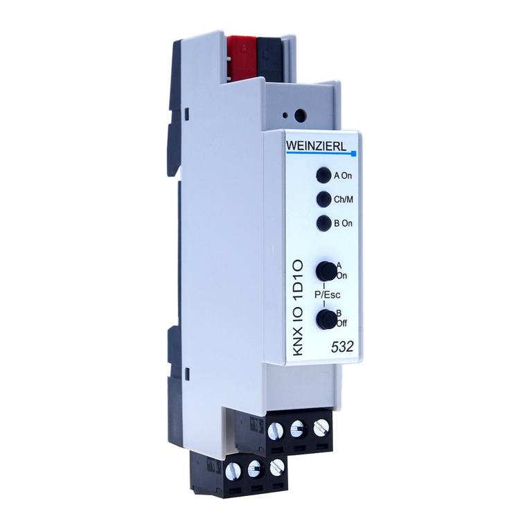
The KNX IO 510.1 secure (2O) is a compact switching actuator with 2 bi-stable relay outputs.
The outputs are connected as closing contacts.
The actuator provides the function for universal outputs including scene control, timer, staircase
lightning and to control heating valves (PWM for thermoelectric valve drives).
Two push buttons and three LEDs allow a local operation and a visualization of the device state.
In addition to the output channels the device includes 16 independent functions for logic or timer
control. The device supports KNX Data Security.
2 Installation and connection
The KNX IO 510.1 secure (2O) is designed for a DIN rail (35 mm) with a width of 1 unit (18 mm).
An installation-friendly design with pluggable screw terminals helps to reduce costs of
commissioning. The actuator has the following controls and displays:
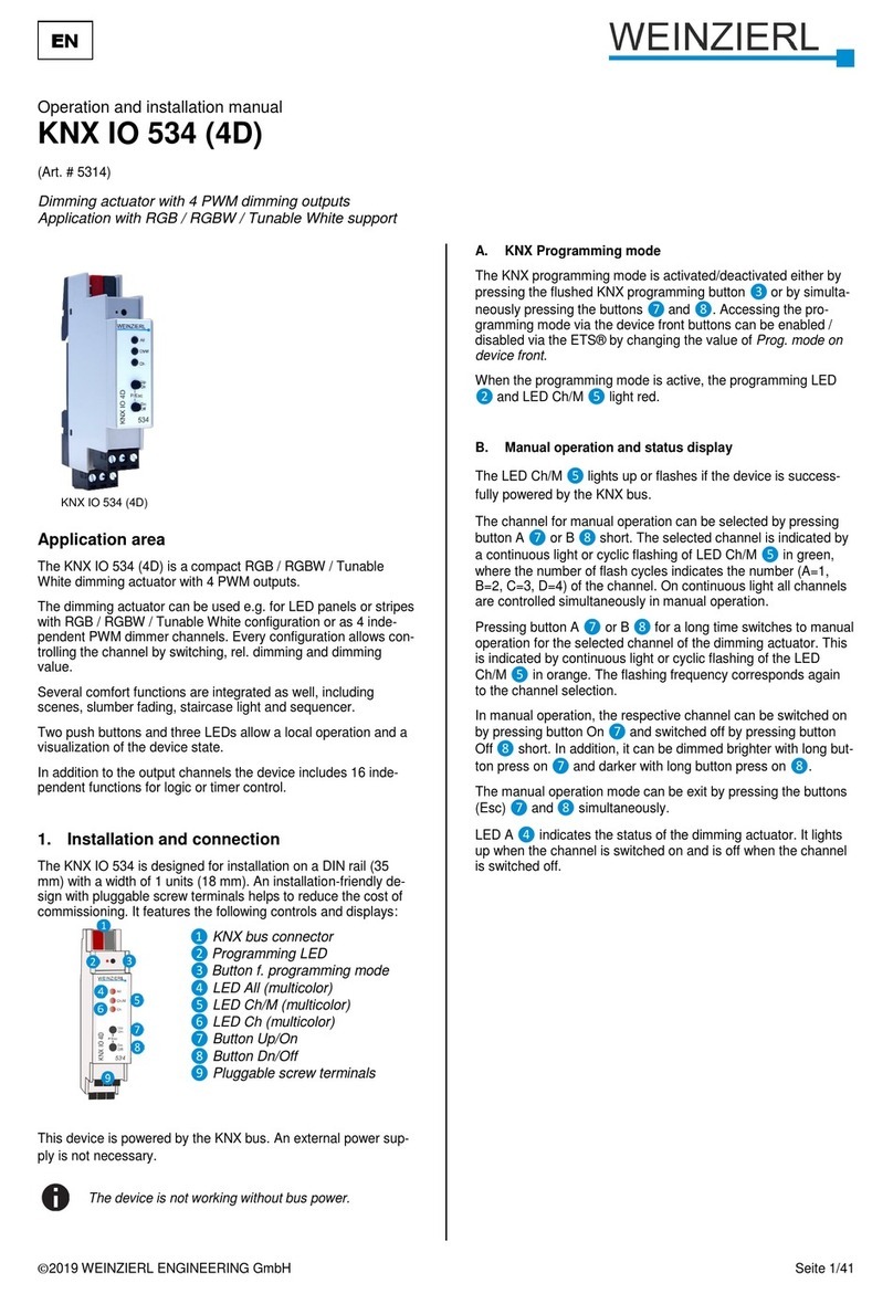
❶KNX bus connection
❷Programming LED
❸Button for programming mode
❹LED A On (multicolor)
❺LED Ch/M (multicolor)
❻LED B On (multicolor)
❼Button A On
❽Button B Off
❾Pluggable screw terminals
This device is powered by the KNX bus. An external power supply is not necessary.
If the bus voltage is missing, the device is without function.

© 2022 WEINZIERL ENGINEERING GmbH Seite 4/30
2.1 KNX programming mode
The KNX programming mode is activated/deactivated either by pressing the recessed KNX
programming button ❸or by simultaneously pressing the buttons (P/Esc) ❼and ❽.
When the programming mode is active, the programming LED ❷and the LED Mode ❺light up
red.
The operation/visualization of the programming mode on the front can be activated/deactivated in
the ETS® on page general settings.
2.2 Manual operation and status display
The LED Ch/M ❺lights up or flashes if the device is successfully powered by the KNX bus.
By pressing button A On ❼long, the manual operation mode will be entered for the first channel
(A). This is indicated by cyclic single flashing of LED Ch/M ❺in orange.
By pressing button B Off ❽long, the manual operation mode will be entered for the second
channel (B). This is indicated by cyclic double flashing of LED Ch/M ❺in orange.
The respective channel can be switched on with button A On ❼and switched off with button B
Off ❽. The manual operation mode can be exit by pressing the buttons (P/Esc) ❼and ❽
simultaneously.
The LED A On ❹is used to display the status of the first channel (A). It lights when the channel is
on and is switched off when the channel is off. Analogously, the LED B On ❻is used to display
the status of the second channel (B).
Summary of the states of LED Ch/M ❺:
LED Status
Meaning
LED lights green
The device operates in normal operating mode.
LED lights red
The programming mode is active.
LED flashes 1x orange
The programming mode is not active.
Manual operation is active:
Switching first channel (A).
LED flashes 2x orange
The programming mode is not active.
Manual operation is active:
Switching second channel (B).
LED flashes red
The programming mode is not active.
Manual operation is not active.
The device is not loaded correctly
e.g. after aborting a download.
LED flashes green
The device is currently loaded by the ETS.

© 2022 WEINZIERL ENGINEERING GmbH Seite 5/30
3 Reset to factory default settings
It is possible to reset the device to its factory default settings.
▪Disconnect the KNX bus connector ❶from the device.
▪Press the KNX programming button ❸and keep it pressed down.
▪Reconnect the KNX bus connector ❶to the device.
▪Keep the KNX programming button ❸pressed for at least another 6 seconds.
▪A short flashing of all LEDs (❷❹❺❻) visualizes the successful reset of the device to
factory default settings.
In the factory default settings, the device has the physical address 15.15.255 and no group
addresses are connected. Also, KNX Data Security is disabled and the initial key (FDSK) must be
used for secure commissioning.
4 Wiring scheme
4.1 Pluggable screw terminals
The pluggable screw terminals ❾on the left/middle terminal pins Ch A / B Out are used as closer.
On the right terminal pins Ch A / B In the common pins are contacted e.g. the voltage to be
switched. Channel A is located on the upper and channel B on the lower terminal.
It is allowed to connect on the upper terminal compared to the lower terminal a different
phase or voltage.

© 2022 WEINZIERL ENGINEERING GmbH Seite 6/30
4.2 Pin assignment
Connection
Icon
Description
1
Ch A
Out
Connection channel A
Output connected as closing contact
2
Ch A
Out
Connection channel A
Output connected as closing contact
3
Ch A
In
Common connection for channel A
e.g. the voltage to be switched
4
Ch B
Out
Connection channel B
Output connected as closing contact
5
Ch B
Out
Connection channel B
Output connected as closing contact
6
Ch B
In
Common connection for channel B
e.g. the voltage to be switched
KNX
+
Positive connection for KNX bus
KNX
-
Ground connection for KNX bus

© 2022 WEINZIERL ENGINEERING GmbH Seite 7/30
5 KNX Security
The KNX standard was extended by KNX Security to protect KNX installations from unauthorized
access. KNX Security reliably prevents the monitoring of communication as well as the
manipulation of the system.
The specification for KNX Security distinguishes between KNX IP Security and KNX Data Security.
KNX IP Security protects the communication over IP while on KNX TP the communication remains
unencrypted. Thus, KNX IP Security can also be used in existing KNX systems and with non-
secure KNX TP devices.
KNX Data Security describes the encryption on telegram level. This means that the telegrams on
the twisted pair bus or via RF (radio frequency) are also encrypted.
Encrypted telegrams are longer than the previously used unencrypted ones. For secure
programming via the bus, it is therefore necessary that the interface used (e.g. USB)
and any intermediate line couplers support the so called KNX long frames.

© 2022 WEINZIERL ENGINEERING GmbH Seite 8/30
6 ETS database
The ETS5 database (for ETS 5.7 or newer) can be downloaded from the product website of the
KNX IO 510.1 secure (2O) (www.weinzierl.de) or from the ETS online catalogue.
The KNX IO 510.1 secure (2O) supports KNX Data Security to protect the device against
unauthorized access from the KNX bus. If the device is programmed via the KNX bus, this is done
with encrypted telegrams.
6.1 Secure commissioning
If the first product is inserted into a project with KNX Security, the ETS prompts you to enter a
project password.
This password protects the ETS project from unauthorized access. This password is not a key that
is used for KNX communication. The entry of the password can be bypassed with “Cancel”, but this
is not recommended for security reasons.
ETS requires a device certificate for each device with KNX Security that is created in the ETS. This
certificate contains the serial number of the device as well as an initial key (FDSK = Factory
Default Setup Key).

© 2022 WEINZIERL ENGINEERING GmbH Seite 9/30
The certificate is printed as text on the device. It can also be scanned from the printed QR code via
a webcam.
The list of all device certificates can be managed in the ETS panel Reports –Project Security.
This initial key is required to safely put a device into operation from the start. Even if the ETS
download is recorded by a third party, the third party has no access to the secured devices
afterwards. During the first secure download, the initial key is replaced by the ETS with a new key
that is generated individually for each device. This prevents persons or devices who may know the
initial key from accessing the device. The initial key is reactivated after a reset to factory default
settings.
The serial number in the certificate enables the ETS to assign the correct key to a device during a
download.

© 2022 WEINZIERL ENGINEERING GmbH Seite 10/30
In the ETS project in the properties of the device, secure commissioning can be activated and the
device certificate can be added:
6.2 Secure group communication
Each object of the device can communicate either encrypted or unencrypted. The encryption is set
under “Security”in the properties of the used group address:

© 2022 WEINZIERL ENGINEERING GmbH Seite 11/30
The setting “Automatic”activates encryption if both objects to be connected can communicate
encrypted. Otherwise encrypted communication between the objects is not possible.
In the overview of communication objects in the ETS project, secured objects can be recognized
by a shield symbol:
A separate key is automatically generated by the ETS for each secured group address. These
keys can also be checked in the ETS panel Reports –Project Security. To enable all devices to
communicate with a secure group address, the keys must be known to all. Therefore a download
must be made into all devices that use this group address when a key is created or changed. A key
is changed by the ETS e.g. when the encryption of a group address is switched off and on again.

© 2022 WEINZIERL ENGINEERING GmbH Seite 12/30
6.3 Description
This page shows the device description and the corresponding connection diagram.
6.4 General settings
Device name (30 characters)
An arbitrary name can be assigned for the KNX IO 510.1 secure (2O). The device name should be
meaningful, e.g. “Living Room”. This helps the clarity of the ETS project.

© 2022 WEINZIERL ENGINEERING GmbH Seite 13/30
Send delay after bus power return
A send delay of telegrams after the return of the bus voltage can be set via this parameter. In this
case, telegrams from the device are sent to the KNX bus in a delayed manner by the set time. This
results in a reduction of the bus load at a bus power return. Other functions such as receiving
telegrams of switching operations of the actuator are not affected by this parameter.
Prog. mode on device front
In addition to the normal programming button ❸the device allows activating the programming
mode on the device front without opening the switchboard cover. The programming mode can be
activated and deactivated via pressing simultaneously both buttons ❼and ❽.
This feature can be enabled and disabled via the parameter “Prog. mode on device front”. The
recessed programming button ❸(next to the Programming LED ❷) is always enabled and not
influenced by this parameter.
Manual operation on device
This parameter is used to configure the manual operation on the device. The manual operation
mode can be disabled or activated (with or without time limitation). The time limit defines the
duration until the automatic return from the manual operation mode back into the normal operating
mode.
The device is in normal operating mode when the manual control is not active. In the manual
operating mode, received switching telegrams are ignored. When the manual operation mode is
terminated (after expiry of the time limit or manually), the last state of the outputs remains, until a
new switching telegram is received again.
The following options are selectable:
▪Disabled
▪Enabled with time limit 1 min
▪Enabled with time limit 10 min
▪Enabled with time limit 30 min
▪Enabled without time limit
Heartbeat
Cyclic sending of values to the KNX bus, to indicate that the device is operational. For the Cycle
time values between 1 min and 24 h are selectable.
Group object
Type KNX
Size
Direction
GO 1 Heartbeat –Trigger
1.001
1 bit
To KNX

© 2022 WEINZIERL ENGINEERING GmbH Seite 14/30
6.5 Actuator A / B: General
Name (30 characters)
An arbitrary name can be assigned for the channel. However, this should be clear and meaningful,
this makes it easier to work with the associated group objects, because the given name is
displayed there as a label. If no name is assigned, the group objects are named
“Actuator A / B: …”.
Function
This parameter defines the functionality of the actuator. The following options are selectable:
▪Disabled
▪Universal output
▪On/Off delay
▪Staircase function
▪Valve actuator (PWM for thermal servo)
More detailed descriptions of the functions can be found in the sections
“Actuator A / B: …”.
Scene function (only for function “Universal output”)
With this parameter the scene function can be enabled or disabled. If this functionality is enabled,
the respective group object as well as the parameter page “Actuator A / B: Scene function”are
displayed for further configuration of scenes 1 –16.
Group object
Type KNX
Size
Direction
GO 12 Actuator A / B: Scene –Activ./Lrn.
18.001
1 bit
From KNX

© 2022 WEINZIERL ENGINEERING GmbH Seite 15/30
Behavior on bus power failure (for function != “Disabled”)
The behavior which is held at the output during the bus power failure can be configured here.
The following options are selectable:
▪No reaction
▪Switch on
▪Switch off
Behavior after bus power return (for function != “Disabled”)
Here the behavior of the output after bus power return can be configured. This behavior will be set
after every device restart (e.g. also on restart after ETS download).
The following options are selectable:
▪No reaction
▪Switch on
▪Switch off
▪State like before bus power failure
Send state (for function != “Disabled”)
This parameter defines the behavior of the state objects:
▪Disabled
State objects are deactivated and not displayed
▪Only on read
State objects send only on request
▪On change
State objects send on value change
▪Cyclic and on change
State objects send cyclically and on value change
Group object
Type KNX
Size
Direction
GO 18 Actuator A / B: Output –State
1.001
1 bit
To KNX
GO 19 Actuator A / B: Valve actuator (PWM) –State*
5.001
1 byte
To KNX
* for function = “Valve actuator (PWM for thermal servo)”
Time for cyclic state
Is selected state object “Cyclic and on change”, in this parameter the cycle time can be set.

© 2022 WEINZIERL ENGINEERING GmbH Seite 16/30
Lock function (for function “Universal output”, “On/Off delay”or “Staircase function”)
With this parameter the lock function can be enabled. If this functionality is activated, the
associated group objects as well as the parameter page “Actuator A / B: Lock function” are
displayed for further configuration. If the lock has been activated via the group object “Lock”, the
received switching telegrams are not executed.
In addition to the lock object, there is also a priority object, which can be switched independently of
the lock. Thus, it is possible to set an output state without affecting other functions.
Group object
Type KNX
Size
Direction
GO 15 Actuator A / B: Lock –Activate
1.001
1 bit
From KNX
GO 16 Actuator A / B: Prior. output –Switch
1.001
1 bit
From KNX
Lock function (for function “Valve actuator (PWM for thermal servo)”)
With this parameter the lock function can be disabled or enabled. If this functionality is activated,
the associated group objects as well as the parameter page “Actuator A / B: Lock function” are
displayed for further configuration. If the lock has been activated via the group object “Lock”, the
received switching telegrams are not executed.
In addition to the lock object, there is also a priority object, which can be used to set a control value
independently of the lock. Thus, it is possible to set an output PWM without affecting other
functions.
When the lock is ended, the last received value (not priority object) is represented as PWM at the
output.
Group object
Type KNX
Size
Direction
GO 15 Actuator A / B: Lock –Activate
1.001
1 bit
From KNX
GO 17 Actuator A / B: Prior. valve actuator (PWM) –
Control value
5.001
1 byte
From KNX
Example of the priority object:
In the case of events in public buildings or in restaurants, the normal operation can be set into an
inoperative state by the lock group object. Thus it is possible to lock during the lecture or concert,
switches that are accessible to unauthorized persons, in order to prevent unmeant switching.
Nevertheless, the individual lamps can controlled by use of the priority object without canceling the
lock.

© 2022 WEINZIERL ENGINEERING GmbH Seite 17/30
6.6 Actuator A / B: Lock function
Condition:
Function is “Universal output”, “On/Off delay” or “Staircase function”.
Polarity of object
This parameter defines, if the lock should be activated by receiving a 1 or by receiving a 0.
The following options are selectable:
▪Lock active on 1
▪Lock active on 0
Behavior on start
This parameter configures, which state the output should set, if the lock activates.
The following options are selectable:
▪No reaction
▪Switch on
▪Switch of
This output state can still be changed by the priority object.

© 2022 WEINZIERL ENGINEERING GmbH Seite 18/30
Behavior at end
This parameter defines, which state the output should set, if the lock deactivates.
The following options are selectable:
▪No reaction
▪Switch on
▪Switch off
▪State before lock
This restores the original state before the lock was activated. Switching telegrams received
during the lock are ignored.
▪State without lock
Here the state of the last received switching telegram is restored. This takes into account
the received switching telegrams during the lock. Thus, when the lock is deactivated, the
last received switching telegram is set.
Condition:
Function is “Valve actuator (PWM for thermal servo)”.
Polarity of object
This parameter defines, if the lock should be activated by receiving a 1 or by receiving a 0.
The following options are selectable:
▪Lock active on 1
▪Lock active on 0

© 2022 WEINZIERL ENGINEERING GmbH Seite 19/30
Behavior on start
This parameter defines, which behavior the output should represent, if the lock activates.
The following options are selectable:
▪No reaction
The PWM value remains as to begin of the lock function.
▪Value
When the lock is activated, a defined PWM value is represented on the output.
Control value (PWM)
If a defined PWM value should be set to the output when the lock is activated, this value can be set
with this parameter.
6.7 Actuator A / B: Universal output
If the universal output is selected on the parameter page “Actuator A / B: General”, the actuator
can be used as a switching output. A parameter for the scene function is also displayed.
Group object
Type KNX
Size
Direction
GO 11 Actuator A / B: Output –Switch
1.001
1 bit
From KNX
6.8 Actuator A / B: Scene function

© 2022 WEINZIERL ENGINEERING GmbH Seite 20/30
Scene 1 –16
These parameters can be used to configure the state, which is set at the output when the
respective scene is executed.
The following options are selectable:
▪No reaction
▪Switch on
▪Switch off
▪Learnable
By using a scene control telegram, the current state at the output can be saved for the
respective scene. This allows the user to customize the scene without ETS download.
Number
This parameter sets any scene number between 1 and 64 to the scene. There must not configured
any scene numbers twice.
6.9 Actuator A / B: On/Off delay
If the on/off delay is selected on the parameter page “Actuator A / B: General”, delayed switching
times can be configured. The “Actuator A / B: On/Off Delay”parameter page is displayed for this
purpose.
Group object
Type KNX
Size
Direction
GO 11 Actuator A / B: Output –Switch
1.001
1 bit
From KNX
On delay time
The duration of the switch-on delay is configured in this parameter.
Input: --1---------0------
Output: --|-T-1-----0------
This manual suits for next models
2
Table of contents
Other Weinzierl Controllers manuals

Weinzierl
Weinzierl KNX IO 534 (4D) Specification sheet

Weinzierl
Weinzierl KNX IO 532 Specification sheet

Weinzierl
Weinzierl KNX IO 511 Specification sheet

Weinzierl
Weinzierl KNX TP Push Button 420 secure Specification sheet

Weinzierl
Weinzierl 5374 Specification sheet

Weinzierl
Weinzierl KNX IP LineMaster 760 Specification sheet
Popular Controllers manuals by other brands

Altronic
Altronic EPC-250 Installation and operating instructions

West Penn Wire
West Penn Wire AV-IP-NC811 Operation manual

Advantech
Advantech AMAX-1220 Series user manual

QuietCool
QuietCool IT-AC-KIT installation guide

ActronAir
ActronAir QUE QZW-100 Installation and user manual

Vemer
Vemer AHT user manual