Weinzierl KNX TP Push Button 420 secure Specification sheet

WEINZIERL ENGINEERING GmbH
Achatz 3-4
84508 Burgkirchen an der Alz
GERMANY
Tel.: +49 8677 / 916 36 –0
E-Mail:info@weinzierl.de
Web: www.weinzierl.de
© 2023 Weinzierl Engineering GmbH Seite 1/50
KNX TP Push Button Insert with KNX Data Security
For MATCH 55 series
KNX TP Push Button 420 secure
KNX TP Push Button Interface 420 secure
Operation and installation manual
(Art. # 5375 Insert with mounting kit and single rocker)
(Art. # 5325 Insert with mounting kit and double rocker)
(Art. # 5385 Insert with connection cable for push button interface)
(Art. # 5482 Insert without mounting kit)

© 2023 Weinzierl Engineering GmbH Seite 2/50
Content
1Application .........................................................................................................................3
2Installation and connection...............................................................................................3
2.1 KNX programming mode......................................................................................................4
2.2 Status display.......................................................................................................................4
3Reset to factory default settings.......................................................................................4
4Wiring scheme ...................................................................................................................5
4.1 Pluggable connections.........................................................................................................5
5Mounting and delivery.......................................................................................................6
5.1 Mounting..............................................................................................................................6
5.2 Delivery................................................................................................................................7
6KNX Security......................................................................................................................7
7ETS database .....................................................................................................................8
7.1 Secure commissioning.........................................................................................................8
7.2 Secure group communication............................................................................................. 11
7.3 Description.........................................................................................................................12
7.4 General settings.................................................................................................................13
7.5 Button A0: General ............................................................................................................15
7.6 Button function “Switching”.................................................................................................16
7.7 Button function “Dimming”.................................................................................................. 18
7.8 Button function “Shutter” ....................................................................................................19
7.9 Button function “Send value” ..............................................................................................23
7.10 Button function “Color” .......................................................................................................25
7.11 Button function “Scene”......................................................................................................29
7.12 Button function “Impulse counter”....................................................................................... 32
7.13 Impulse counter “Scaled counter (e.g. [kWh])” ...................................................................33
7.14 Impulse counter “Rate of change (e.g. [kW], [m/s], [km/h])”................................................36
7.15 Button function “Generic” ...................................................................................................39
7.16 Sequence controller........................................................................................................... 42
7.17 Logic / Timer...................................................................................................................... 45
7.18 Function 1 –10: Timer.......................................................................................................46
7.19 Function 1 –10: Logic........................................................................................................48
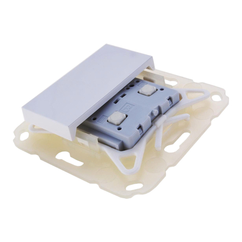
© 2023 Weinzierl Engineering GmbH Seite 3/50
1 Application
The KNX TP Push Button 420 secure is a push button insert with integrated bus coupling unit. The
device is available with one or two rockers. Each rocker offers two pressure points (up/down).
The device is part of the MATCH 55 push button series. With the supplied installation kit, the push
button fits mechanically to numerous switch ranges available on the market with internal
dimensions of 55 mm. The soft and quiet push button operation allows the installation in bedrooms
and living rooms.
The application offers extensive functions for switching, dimming, shutter, valuator, scene and
colour control as well as a sequence controller. Each button on a rocker can be configured
individually. The flexible operating concept also allows different functions on one button depending
on the setting.
The KNX TP Push Button 420 secure has pluggable connections to operate the device as binary
input or pulse counter with 4 independent channels. Via these connections, 2 LEDs can also be
operated externally.
In addition, the device contains 10 independent logic or time functions. The device supports KNX
Data Security.
2 Installation and connection
The KNX TP Push Button 420 secure is suitable for numerous switch ranges available on the
market with 55 mm internal dimensions. The insert has the following operating elements and
displays:
❶KNX bus connector
❷Pluggable connections
❸Button/LED for programming mode
❹Button/LED A0
❺Button/LED A1
❻Button/LED B0
❼Button/LED B1
❽LED Top [0]
❾LED Bottom [1]
If the bus voltage is missing, the device is without function.

© 2023 Weinzierl Engineering GmbH Seite 4/50
2.1 KNX programming mode
The KNX programming mode is activated/deactivated either by pressing the recessed KNX
programming button ❸or by simultaneously pressing the buttons ❹and ❻for approx. 6
seconds.
When the programming mode is active, the programming LED ❸lights up red.
The operation of the programming mode via the buttons ❹and ❻can be activated/deactivated
in the ETS® on page general settings.
2.2 Status display
Summary of the states of programming LED ❸:
Summary of the states of LED Top [0] ❽:
3 Reset to factory default settings
It is possible to reset the device to its factory default settings.
▪Disconnect the KNX bus connector ❶from the device.
▪Press the KNX programming button ❸and keep it pressed down.
▪Reconnect the KNX bus connector ❶to the device.
▪Keep the KNX programming button ❸pressed for at least another 6 seconds.
▪A short flashing of all LEDs (❸❹❺❻❼❽❾) visualizes the successful reset of the
device to factory default settings.
In the factory default settings, the device has the physical address 15.15.255 and no group
addresses are connected. Also, KNX Data Security is disabled and the initial key (FDSK) must be
used for secure commissioning.
LED Status
Meaning
LED lights red
Programming mode is active.
LED flashes red
Programming mode is not active.
The device is not properly loaded
e.g. after an interrupted download.
LED Status
Meaning
LED flashes green
The device is currently loaded by the ETS.

© 2023 Weinzierl Engineering GmbH Seite 5/50
4 Wiring scheme
4.1 Pluggable connections
A connection cable is available for operating the device as binary input or pulse counter, the
assignment is as follows:
Connection pair
Color of the connection cable
Function
A0
White
Button A0
Black
Common ground
A1
Brown
Button A1
Black
Common ground
B0
Green
Button B0
Black
Common ground
B1
Yellow
Button B1
Black
Common ground
Additionally, 2 LEDs can be controlled externally:
Connection pair
Color of the connection cable
Function
LED0
Gray
LED Top [0]
Black
Common ground
LED1
Red
LED Bottom [1]
Black
Common ground
All black connecting cables are internally connected to ground in the device.
The KNX connection is located on the underside of the device.

© 2023 Weinzierl Engineering GmbH Seite 6/50
5 Mounting and delivery
5.1 Mounting
Mounting of the KNX TP Push Button 420 secure ①:
▪Insert the device ①from above into the holding frame ②. The device snaps into the
retaining lugs ③of the holding frame on the left and right and sits flush on the four
retaining lugs ④.
▪Fasten the wall mounting frame ⑤in the desired installation position (with screws or
adhesive pad) –make sure that the retaining straps ⑦point up and down.
▪Place the decorative frame ⑥on the wall mounting frame ⑤and then place the device ①
locked into the holding frame ②from above. The wall mounting frame ⑤snaps into the
retaining lugs ⑧of the holding frame ②with the retaining straps ⑦.
▪Finally, place the rocker ⑨(single rocker or double rocker depending on the model) on the
KNX TP Push Button 420 secure ①and clip it in.
For dismantling, proceed in reverse order.
When connecting to the KNX bus, ensure correct polarity or orientation of the bus
connector (see imprint on the underside of the device).

© 2023 Weinzierl Engineering GmbH Seite 7/50
5.2 Delivery
KNX TP Push Button 420 secure, single rocker (Art. # 5375):
▪Push button insert ①
▪Holding frame ②
▪Wall mounting frame ⑤
▪Single rocker (no picture)
KNX TP Push Button 420 secure, double rocker (Art. # 5325):
▪Push button insert ①
▪Holding frame ②
▪Wall mounting frame ⑤
▪Double rocker ⑨
KNX TP Push Button Interface 420 secure (Art. # 5385):
The device is suitable as a binary input for connecting up to four conventional push buttons or dry
contacts. In addition, the device offers two outputs for LEDs. The integrated push buttons and
LEDs allow a quick test of the configuration.
▪Push button insert ①
▪Connection cable for push button interface (see page 1)
KNX TP Push Button Insert 420 secure (Art. # 5482):
The device comes without rockers or mounting kit.
▪Push button insert ①
6 KNX Security
The KNX standard was extended by KNX Security to protect KNX installations from unauthorized
access. KNX Security reliably prevents the monitoring of communication as well as the
manipulation of the system.
The specification for KNX Security distinguishes between KNX IP Security and KNX Data Security.
KNX IP Security protects the communication over IP while on KNX TP the communication remains
unencrypted. Thus, KNX IP Security can also be used in existing KNX systems and with non-
secure KNX TP devices.
KNX Data Security describes the encryption on telegram level. This means that the telegrams on
the twisted pair bus or via RF (radio frequency) are also encrypted.
Encrypted telegrams are longer than the previously used unencrypted ones. For secure
programming via the bus, it is therefore necessary that the interface used (e.g. USB)
and any intermediate line couplers support the so called KNX long frames.

© 2023 Weinzierl Engineering GmbH Seite 8/50
7 ETS database
The ETS5 database (for ETS 5.7 or newer) can be downloaded from the product website of the
KNX TP Push Button 420 secure (www.weinzierl.de) or from the ETS online catalogue.
The KNX TP Push Button 420 secure supports KNX Data Security to protect the device against
unauthorized access from the KNX bus. If the device is programmed via the KNX bus, this is done
with encrypted telegrams.
7.1 Secure commissioning
If the first product is inserted into a project with KNX Security, the ETS prompts you to enter a
project password.
This password protects the ETS project from unauthorized access. This password is not a key that
is used for KNX communication. The entry of the password can be bypassed with “Cancel”, but this
is not recommended for security reasons.
ETS requires a device certificate for each device with KNX Security that is created in the ETS. This
certificate contains the serial number of the device as well as an initial key (FDSK = Factory
Default Setup Key).

© 2023 Weinzierl Engineering GmbH Seite 9/50
The certificate is printed as text on the device. It can also be scanned from the printed QR code via
a webcam.
The list of all device certificates can be managed in the ETS panel Reports –Project Security.
This initial key is required to safely put a device into operation from the start. Even if the ETS
download is recorded by a third party, the third party has no access to the secured devices
afterwards. During the first secure download, the initial key is replaced by the ETS with a new key
that is generated individually for each device. This prevents persons or devices who may know the
initial key from accessing the device. The initial key is reactivated after a reset to factory default
settings.
The serial number in the certificate enables the ETS to assign the correct key to a device during a
download.

© 2023 Weinzierl Engineering GmbH Seite 10/50
In the ETS project in the properties of the device, secure commissioning can be activated and the
device certificate can be added:

© 2023 Weinzierl Engineering GmbH Seite 11/50
7.2 Secure group communication
Each object of the device can communicate either encrypted or unencrypted. The encryption is set
under “Security”in the properties of the used group address:
The setting “Automatic”activates encryption if both objects to be connected can communicate
encrypted. Otherwise encrypted communication between the objects is not possible.
In the overview of communication objects in the ETS project, secured objects can be recognized
by a shield symbol:
A separate key is automatically generated by the ETS for each secured group address. These
keys can also be checked in the ETS panel Reports –Project Security. To enable all devices to
communicate with a secure group address, the keys must be known to all. Therefore a download
must be made into all devices that use this group address when a key is created or changed. A key
is changed by the ETS e.g. when the encryption of a group address is switched off and on again.

© 2023 Weinzierl Engineering GmbH Seite 12/50
7.3 Description
This page shows the device description and the associated wiring scheme.

© 2023 Weinzierl Engineering GmbH Seite 13/50
7.4 General settings
Device name (30 characters)
An arbitrary name can be assigned for the KNX TP Push Button 420 secure. The device name
should be meaningful, e.g. “Living Room”. This helps the clarity of the ETS project.
Send delay after bus power return
A send delay of telegrams after the return of the bus voltage can be set via this parameter. In this
case, telegrams from the device are sent to the KNX bus in a delayed manner by the set time. This
results in a reduction of the bus load at a bus power return. Other functions such as receiving
telegrams or query of the inputs are not affected by this parameter
Prog. mode (press A0+B0 for 6 sec.)
In addition to the normal programming button ❸the device allows activating the programming
mode on the device front without removing the rocker. The programming mode can be activated
and deactivated via pressing simultaneously both buttons ❹and ❻for 6 seconds.
This feature can be enabled and disabled via the parameter “Prog. mode (press A0+B0 for 6
sec.)”. The recessed programming button ❸is always enabled and not influenced by this
parameter.
The prog. mode (A0+B0) should be deactivated if push button functions are configured for
actuations of more than 6 seconds (e.g. moving shutter via Deadman switch)
Heartbeat cycle time
Sends cyclically the value 1 to the KNX bus to indicate that the device is currently ready for
operation. The cycle time can be selected between 1 minute and 24 hours.
Group object
Type KNX
Size
Direction
GO 1 Heartbeat –Trigger
1.001
1 Bit
To KNX

© 2023 Weinzierl Engineering GmbH Seite 14/50
Long button press after
Here you can set the time for detecting a long actuation, this time is valid for all inputs/buttons.
LED A0
LED A1
LED B0
LED B1
Here the operating mode of the LEDs in normal operation can be set, it is selectable:
▪Disabled
LED is disabled always.
▪Enabled
LED is enabled always.
▪Via group object
LED is operated only via group object.
▪Input/Key state
LED is operated only via input/key.
LED Top [0]
LED Bottom [1]
Here the operating mode of the LEDs in normal operation can be set, it is selectable:
▪Disabled
LED is disabled always.
▪Enabled
LED is enabled always.
▪Via group object
LED is operated only via group object.
▪Bus traffic
LED indicates bus communication.

© 2023 Weinzierl Engineering GmbH Seite 15/50
7.5 Button A0: General
Name (30 characters)
An arbitrary name can be assigned for the input/button. However, this should be clear and
meaningful, this makes it easier to work with the associated group objects, because the given
name is displayed there as a label. If no name is assigned, the group objects are named “Button
…” with the button number engraved on the housing, which is also used in this manual. The 1st
input/button will be described below, the functioning of the other 3 inputs/buttons is according to
the 1st.
Button function
The following functions are selectable:
▪Switching
▪Dimming
▪Shutter
▪Send value
▪Color
▪Scene
▪Impulse counter
▪Generic

© 2023 Weinzierl Engineering GmbH Seite 16/50
7.6 Button function “Switching”
If the switching function is selected, up to 2 binary switching telegrams can be sent via the
following objects:
Group object
Type KNX
Size
Direction
GO 11 Button A0: Object a –Switch
1.001
1 Bit
To KNX
GO 12 Button A0: Object b –Switch
1.001
1 Bit
To KNX
Object b is only visible when activated by parameter.
The time for detection of a long button press can be set in the general parameters and is valid for
all inputs/buttons.
User control
The parameter “User control”determines whether telegrams are sent when the input is changed
(e.g. key switches) or when the button is operated short/long (e.g. button for switching/dimming).

© 2023 Weinzierl Engineering GmbH Seite 17/50
Function of object a/b on press
Function of object a/b on short press
Function of object a/b on release
Function of object a/b on long press
It is selectable for each object a and b, which telegram is sent on press and release or on
short/long button press.
The following options are available:
▪No reaction
▪Switch on
▪Switch off
▪Toggle
On toggle the last value received from the bus is evaluated if the write flag is activated on
the object.
Object b
Here object b can be enabled and configured.
Cyclic sending
Cyclic sending can be configured independently for states 0 and 1:
Send interval for state 0
Send interval for state 1
The send interval of the respective state can be set here.
Button lock
With this parameter the button lock can be enabled. If the lock has been activated via the group
object, no telegrams are triggered by state changes of the input/button.
Group object
Type KNX
Size
Direction
GO 16 Button A0: Lock –Activate
1.001
1 Bit
From KNX
Polarity of object (only for button lock)
This parameter defines, if the lock should be activated by receiving a 1 or by receiving a 0. The
respective opposite telegram deactivates the lock again.
Behavior of object a/b on start (only for button lock)
The telegram can be configured here, which is sent on the according object when the lock is
activated.
Behavior of object a/b at end (only for button lock)
The telegram can be configured here, which is sent on the according object when the lock is
deactivated.

© 2023 Weinzierl Engineering GmbH Seite 18/50
7.7 Button function “Dimming”
On selection of button function dimming following objects are visible:
Group object
Type KNX
Size
Direction
GO 11 Button A0: Dimming on/off –Switch
1.001
1 Bit
To KNX
GO 12 Button A0: Dimming relative –Brighter/Darker
3.007
4 Bit
To KNX
The time for detection of a long button press can be set in the general parameters and is valid for
all inputs/buttons.
Dimming function
The parameter “Dimming function”determines whether only one switching/dimming direction or 1-
button control is to be used.
▪On / Dim brighter
▪Off / Dim darker
▪Toggle direction
On toggle direction, the last value received from the bus is evaluated if the write flag is
activated on the object. This applies to object 11 and object 12.
If the input/button detects a short button press, a switching telegram is sent via object 11. On long
button press, a relative dimming is sent over the entire dimming range to object 12. When
releasing after long button press, a dimming-stop telegram is sent via object 12.
Dimming direction after switch on (only for toggle direction)
This parameter is only visible on toggle direction and determines the dimming direction of the next
dimming command following an ON telegram.

© 2023 Weinzierl Engineering GmbH Seite 19/50
Button lock
With this parameter the button lock can be enabled. If the lock has been activated via the group
object, no telegrams are triggered by state changes of the input/button.
Group object
Type KNX
Size
Direction
GO 16 Button A0: Lock –Activate
1.001
1 Bit
From KNX
Polarity of object (only for button lock)
This parameter defines, if the lock should be activated by receiving a 1 or by receiving a 0. The
respective opposite telegram deactivates the lock again.
Behavior of object a/b on start (only for button lock)
The telegram can be configured here, which is sent on the according object when the lock is
activated.
Behavior of object a/b at end (only for button lock)
The telegram can be configured here, which is sent on the according object when the lock is
deactivated.
7.8 Button function “Shutter”
On selection of button function shutter following objects are visible:
Group object
Type KNX
Size
Direction
GO 11 Button A0: Drive start –Up/Down
1.008
1 Bit
To KNX
GO 12 Button A0: Drive stop –Step/Stop
1.007
1 Bit
To KNX
The time for detection of a long button press can be set in the general parameters and is valid for
all inputs/buttons.

© 2023 Weinzierl Engineering GmbH Seite 20/50
Shutter direction
The parameter “Shutter direction”determines whether only one shutter direction or 1-button control
is to be used.
▪Up
▪Down
▪Toggle
If the write flags are set, the shutter objects evaluate the last value received from the bus.
This keeps the direction and state of the shutter in the button up to date.
User control
The parameter “User control”determines the sending of telegrams on short and long button press:
▪KNX standard: Long / Short
Long actuation: Drive command via object 11
Short actuation: Stop/Step command via object 12
Very long actuation: Additional function
▪KNX standard with turning time
Long actuation: Drive command via object 11
Release after long actuation within turning time: Stop/Step command via object 12
Release after long actuation after turning time: No reaction
Short actuation: Stop/Step command via object 12
Very long actuation: Additional function
▪KNX Inverted: Short / Long
Short actuation: Drive command via object 11
Long actuation: Stop/Step command via object 12
Actuation during drive: Stop/Step command via object 12
Very long actuation: Additional function
▪Short / Short
Short actuation: Drive command via object 11
Actuation during drive: Stop/Step command via object12
Long actuation: Additional function
▪Short / Short plus Long with turning time
Short actuation: Drive command via object 11
Long actuation: Drive command via object 11
Release after long actuation within turning time: Stop/Step command via object 12
Release after long actuation after turning time: No reaction
Actuation during drive: Stop/Step command via object 12
Very long actuation: Additional function
▪Hold (Deadman switch)
On actuation: Drive command via object 11
On release: Stop/Step command via object 12
This manual suits for next models
5
Table of contents
Other Weinzierl Controllers manuals

Weinzierl
Weinzierl 5374 Specification sheet

Weinzierl
Weinzierl KNX IP LineMaster 760 Specification sheet

Weinzierl
Weinzierl KNX IO 510.1 secure Specification sheet

Weinzierl
Weinzierl KNX IO 532 Specification sheet

Weinzierl
Weinzierl KNX IO 534 (4D) Specification sheet

Weinzierl
Weinzierl KNX IO 511 Specification sheet