WEISS ROBOTICS GRIPLINK-ET4 User manual

GRIPLINK PLUG-IN FOR EPSON
Version 1.0.0

- 1 -
Table of contents
1 Introduction........................................................................................................................ 2
1.1 Notation and symbols......................................................................................................... 2
1.2 Intended use....................................................................................................................... 2
1.3 System requirements.......................................................................................................... 2
1.4 License terms...................................................................................................................... 3
2 Installation .......................................................................................................................... 4
2.1 Software installation........................................................................................................... 4
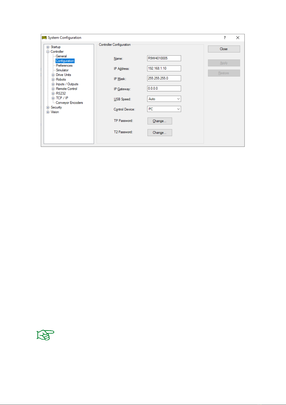
2.2 Network configuration........................................................................................................ 4
2.3 Workpiece detection and monitoring................................................................................. 5
3 Command set reference ..................................................................................................... 7
3.1 Open connection - CONNECT.............................................................................................. 8
3.2 Enable drive - ENABLE......................................................................................................... 9
3.3 Get Grip State –GET STATE .............................................................................................. 10
3.4 Read gripping state from global variable.......................................................................... 11
3.5 Disable drive - DISABLE..................................................................................................... 12
3.6 Disable drives of all modules connected –DISABLE ALL .................................................. 14
3.7 Reference gripper - HOME................................................................................................ 15
3.8 Reference multiple grippers –MHOME............................................................................ 16
3.9 Grip part - GRIP................................................................................................................. 17
3.10 Grip part with multiple grippers –MGRIP ........................................................................ 18
3.11 Release part - RELEASE ..................................................................................................... 19
3.12 Release part with multiple grippers –MRELEASE............................................................. 20
3.13 Get finger position –GET POSITION ................................................................................. 21
3.14 Control gripping force retention - PERMAGRIP................................................................ 22
3.15 Control gripping force retention for multiple grippers –MPERMAGRIP.......................... 23
3.16 Control of the LED display –LED........................................................................................ 24
4 Error Handling................................................................................................................... 25
4.1 Handle errors in GRIPLINK functions ............................................................................... 25
4.2 Handle errors in GRIPLINK background daemon.............................................................. 26

- 2 -
1Introduction
With the GRIPLINK technology, servo-electric and smart pneumatic gripping modules from WEISS
ROBOTICS can be controlled by robot controllers of all leading robot brands via simple TCP/IP network
connections.
The GRIPLINK plug-in for EPSON is the software link between the GRIPLINK-ET4 interface converter
and the robot controller and enables the easy integration of WEISS ROBOTICS’ GRIPLINK technology
into EPSON robot systems.
This manual describes the functions of the GRIPLINK plug-in. For information about
installation and operation of the GRIPLINK-ET4 interface converter please refer to the
GRIPLINK-ET4 user’s manual. The manual can be found online on
www.griplink.de/manuals
1.1 Notation and symbols
For a better understanding, the following symbols are used in this manual:
Functional or safety relevant information. Non-compliance may endanger the safety of
personnel and the system, damage the device or impair its function.
Additional information for a better understanding of the described facts.
Reference to further information.
1.2 Intended use
The software “GRIPLINK plug-in“ is intended for communication between the GRIPLINK-ET4 interface
converter from WEISS ROBOTICS and a robot controller. The requirements of the applicable guidelines
as well as the installation and operation instructions in this manual must be noted and adhered to. Any
other use or use beyond that is considered improper use. The manufacturer is not liable for any
damage resulting from this.
1.3 System requirements
In order to run the GRIPLINK plug-in, the following EPSON products are required:
•EPSON Robot Controller RC700-A or RC90-B
•EPSON RC+ 7.0 programming environment, version 7.4.5 or higher
Please contact EPSON or your EPSON distributor in order to purchase these products.

- 3 -
1.4 License terms
The GRIPLINK plug-in is protected by copyright. The software package includes the applicable license
terms. By installing and using the GRIPLINK plug-in, the user accepts these license terms.

- 4 -
2Installation
2.1 Software installation
To operate the GRIPLINK-ET4, the GRIPLINK plug-in provided by WEISS ROBOTICS is required on the
robot controller. To install the GRIPLINK plug-in, please execute the following steps:
Please make sure the most recent version of the GRIPLINK plug-in is used. It can be
downloaded from www.griplink.de/software.
1. Unzip the previously downloaded ZIP archive with the GRIPLINK plug-in into a directory of
your choice
2. Create a new project in the EPSON RC+ programming environment or open an existing
project to add the GRIPLINK plug-in.
3. Import the extracted files into your EPSON RC+ project using the menu item "File" ->
"Import". Please note that the package contains several files with the extensions *.prg and
*.inc. Both file types must be imported separately.
4. The necessary functions for using the GRIPLINK-ET4 in your project are now available.
2.2 Network configuration
The connection between the GRIPLINK-ET4 and the robot controller is established via TCP/IP
networking. To use TCP/IP networking, the robot controller must be assigned an IP address in the
system settings. Please note that the IP address of the robot controller must be in the same subnet as
the IP address of the GRIPLINK-ET4.
The IP address of the GRIPLINK is set to 192.168.1.40 by default and can be adjusted via its web
interface. To do this, connect the GRIPLINK-ET4 to a PC or laptop and open the web interface in your
favorite browser by entering http://192.168.1.40 into the address bar. You can access the IP settings
by pressing the "Config" button.
The GRIPLINK command interface accepts incoming connections on port 10001 (TCP).
For more information about the configuration of the GRIPLINK-ET4, please refer to the
associated user’s manual.
The IP address of the robot controller can be set in the EPSON RC+ programming environment via the
menu item "Settings" → "System Settings" in "Controller" → "Configuration" (cf. Figure 1).
The IP addresses of both the robot controller and the GRIPLINK-ET4 interface converter
must be located within the same subnet range. Please contact your network
administrator if you experience any problems assigning appropriate IP addresses to the
devices.

- 5 -
Figure 1: Setting the IP address for the robot controller
2.3 Workpiece detection and monitoring
Gripping modules from WEISS ROBOTICS have integrated workpiece detection and monitoring, which
makes it possible to permanently monitor the entire gripping process without additional sensors, thus
significantly increasing the reliability of the handling process.
The GRIPLINK plug-in permanently communicates with the gripping module in the background and
continuously queries its status. This way, the robot program can react immediately to workpieces that
are not available or have been lost.
2.3.1 Workpiece detection
The workpiece detection makes it possible to immediately recognize whether a workpiece has been
gripped correctly or not. If the gripping fingers are blocked within the specified position window and
the desired gripping force has been reached, the gripping module changes to HOLDING state.
Otherwise the gripping module changes to NO PART state. The gripping state after gripping the
workpiece is given by the function Griplink_Grip() (cf. chapter 3.9) as return value. In addition, the
gripping state can be queried at any time using the function Griplink_GetState() (cf. chapter 3.3).
A detailed description of the gripping states can be found in the operating instructions
for the respective gripping module.

- 6 -
2.3.2 Workpiece monitoring
After a workpiece has been gripped correctly, i. e. the HOLDING state has been reached, the integrated
workpiece monitoring starts automatically on the gripping module. If the workpiece now gets lost or
removed before the Griplink_Release() command (see chapter 3.11) is executed to release the
workpiece intentionally, the status of the gripping module changes to PART LOST.
The behavior of the robot program in case of a lost workpiece can be specified when the gripping
module is activated using the Griplink_Enable() command (see chapter 3.2). If the workpiece
monitoring is activated here, the robot program will be interrupted throwing an error. If, on the other
hand, the workpiece monitoring is not activated, the GRIPLINK plug-in will silently ignore the lost
workpiece and the robot program will continue without an error message.

- 7 -
3Command set reference
The GRIPLINK plug-in provides a number of gripping functions. Both single and multi-gripper
commands are available.
Multi-gripper commands
With the multi-gripper commands, several gripping modules can be addressed at once. These
commands are particularly suitable for handling large or flexible workpieces with multiple gripping
modules simultaneously.
The basic program flow with the GRIPLINK plug-in is always as follows:
1. Establish connection with CONNECT
2. Activate gripping module and connection monitoring with ENABLE
3. For servo gripping modules without absolute encoder: Reference gripping module with
HOME / MHOME
4. Gripping / releasing with GRIP / MGRIP or RELEASE / MRELEASE
The following chapters describe the available commands provided by the plug-in in detail.
Function
Description
Griplink_Connect()
Open connection
Griplink_Enable()
Enable gripping module
Griplink_Disable()
Disable gripping module
Griplink DisableAll()
Disable all connected gripping modules
Griplink_GetState()
Query gripping state
Griplink_Home()
Reference gripping module
Griplink_MulitHome
Reference multiple gripping modules
Griplink_Grip()
Grip workpiece
Griplink_MultiGrip()
Grip workpiece with multiple grippers
Griplink_Release()
Release workpiece
Griplink_MultiRelease()
Release workpiece with multiple grippers
Griplink_GetPos()
Get finger position
Griplink_Permagrip()
Control gripping force retention PERMAGRIP®
Griplink_MultiPermagrip()
Control gripping force retention for multiple grippers
Griplink_LED()
Control LED display

- 8 -
3.1 Open connection - CONNECT
This command establishes the connection between the GRIPLINK-ET4 interface converter and the
robot controller. To open a network connection, one of 16 available so-called Ports (range 201 to 216)
on the robot controller must be selected. In order to be able to permanently monitor the connection
and the status of the connected gripping modules, a separate task will be started on the robot
controller that runs in background and continuously checks the gripping state. The identification
number of this task can be selected freely within the allowed range. In addition, a Timer and a SyncLock
object provided by the robot controller will be used. The IDs of these objects can also be selected freely
within the allowed range.
Please note that the selected Port as well as the Task ID, Timer ID and SyncLock ID must
be available exclusively for the GRIPLINK plug-in and must not be used anywhere else in
the robot program.
The IP address of the GRIPLINK-ET4 can be changed via the web interface.
Signature
Function Griplink_Connect(strIPAddr$ As String, intControllerPortNo As
Integer, intTaskId As Integer, intTimerId As Integer, intSyncLockId As
Integer)
Parameters
strIPAddr$ IP adress of the GRIPLINK interface converter as string
intControllerPortNumber Port number to be used for the TCP/IP connection. Range
between 201 und 216.
intTaskId Task ID to be used for the background task (daemon). Must be
between 1 and 31. Usually Task ID 1 is used by the main
program, so at least Task ID 2 or higher must be used.
intTimerId Timer ID of the timer to be used. Range between 0 and 63.
intSyncLockId Lock ID of the SyncLock object to be used. Range between 0 and
63.
Return value
-
Example
Open a connection to the GRIPLINK with IP address 192.168.0.40 by using Port 201, Task ID 2,
Timer 0 and SyncLock ID 0:
Griplink_Connect(“192.168.0.40”, 201, 2, 0, 0)

- 9 -
3.2 Enable drive - ENABLE
This command activates the gripping module and the connection monitoring. If the connection to the
gripping module gets lost (e.g. due to a cable break), an error will be raised and the robot program will
be stopped. In addition, all ongoing robot motions will be stopped. After enabling, the connection
monitoring can be disabled with the command Griplink_Disable() (cf. chapter 3.4), e. g. to perform a
tool change.
Workpiece monitoring
The workpiece monitoring can be switched on or off by setting the function’s
boolEnableGripMonitoring argument. If the workpiece monitoring is active and the gripping module
loses a previously picked workpiece, an error will be raised and the robot program will be stopped. If
this behavior is not desired, the workpiece monitoring must be disabled.
Griplink_Enable() must be executed after Griplink_Connect() for all connected gripping modules. If
GRIPLINK commands are executed before Griplink_Enable() is executed, an error will be raised and the
robot program will be stopped.
Signature
Function Griplink_Enable(ubGripperID As UByte, boolEnableGripMonitoring
As Boolean) As Integer
Parameters
ubGripperID Index of the gripping module (0 to 3)
boolEnableGripMonitoring Workpiece monitoring: True = on, False = off
Return value
Current gripping state (cf. 4)
Example
Enable drive and workpiece monitoring for the gripping module connected at GRIPLINK port 0:
Integer intGripState
intGripState = Griplink_Enable(0, True)

- 10 -
3.3 Get Grip State –GET STATE
This function returns the gripping state of the selected gripping module. The gripping state is provided
as an integer value. To simplify and improve readability, the file Griplink.inc defines constants that can
be used for processing gripping states.
Signature
Function Griplink_GetState(ubGripperID As UByte) As Integer
Parameters
ubGripperID Index of the gripping module (0 to 3)
Return value
Current gripping state (cf. 4)
Example
Wait until the gripping state of the gripping module at port 2 changes to HOLDING (4):
#include “Griplink.inc“
'Query gripping state of gripping module at port 2
Integer intGripState
'The constant GS_HOLDING is defined in Griplink.inc
Do While intGripState <> GS_HOLDING
intGripState = Griplink_GetState(2)
Loop

- 11 -
3.4 Read gripping state from global variable
The GRIPLINK plug-in provides four global status variables which, if a gripping module is connected and
activated via Griplink_Enable(), permanently provide the gripping status of the respective gripping
module as an integer value:
1. Griplink_intGripperState0 - Gripping state of the gripping module at port 0
2. Griplink_intGripperState1 - Gripping state of the gripping module at port 1
3. Griplink_intGripperState2 - Gripping state of the gripping module at port 2
4. Griplink_intGripperState3 - Gripping state of the gripping module at port 3
These global variables can be used for example to interrupt ongoing robot motions in case of a lost
workpiece or faulty gripping module. Especially if the integrated workpiece monitoring (cf. chapter 2.3)
is not used, customer-specific behavior in the event of workpiece loss can be implemented using the
commands Sense and Till (see SPEL + reference manual of the EPSON robot system).
Example
The following program interrupts the motion performed using Jump P4 if the global variable
Griplink_intGripperState0, which permanently contains the gripping status of the gripping module at
port 0, reaches a value other than GS_HOLDING. The JS command can then be used to determine
whether the motion has been completed or interrupted. If the motion was interrupted, error 8101 will
be raised.
Sense Griplink_intGripperState0 <> GS_HOLDING
Jump P4 Sense
If JS = True Then
Error 8101
EndIf
For more information on the Jump and Sense commands, please refer to the
documentation of the EPSON robot system.

- 12 -
3.5 Disable drive - DISABLE
This function can be used, for example, when using an automatic tool changer. It deactivates the drive
of the selected gripping module. If the drive is deactivated, the connection monitoring is also switched
off and an interruption of the connection between the GRIPLINK and the gripping module no longer
leads to an error. The connection monitoring can be reactivated via Griplink_Enable().
Signature
Function Griplink_Disable(ubGripperID As UByte) As Integer
Parameters
ubGripperID Index of the gripping module (0 to 3)
Return value
Current gripping state (cf. Table 1)
Example
Change gripping module at port 1:
'Open connection between robot controller and GRIPLINK
Griplink_Connect(“192.168.1.40“, 201, 2, 0, 0)
'Enable drive and workpiece monitoring for gripping module at port 1
Griplink_Enable(1, True)
'Execute program (e. g. pick & place)
'…
'Disable gripping module at port 1
Griplink_Disable(1)
'Now the gripping module can be removed without raising an error.
'Enable new gripping module
Griplink_Enable(1, True)
'Continue with program
Gripping State
Constant
Code
Description
NOT CONNECTED
GS_NOT_CONNECTED
0
Gripper not connected
NOT INITIALIZED
GS_NOT_INITIALIZED
1
Gripper not initialized
IDLE
GS_IDLE
2
Gripper idle, ready for operation
RELEASED
GS_RELEASED
3
Workpiece released
NO PART
GS_NO_PART
4
Workpiece not found
HOLDING
GS_HOLDING
5
Holding workpiece
PART LOST
GS_PART_LOST
6
Workpiece lost
FAULT
GS_FAULT
7
Error

- 13 -
Table 1: Grip States

- 14 -
3.6 Disable drives of all modules connected –DISABLE ALL
This function disables the drives of all connected gripping modules. It can be used for example in case
of an emergency stop to switch off all gripping modules. If the drive is deactivated, the connection
monitoring is also switched off and an interruption of the connection between the GRIPLINK and the
gripping module does not lead to an error. The connection monitoring can be reactivated via
Griplink_Enable() (see section 3.2).
Signature
Function Griplink_DisableAll As Boolean
Parameters
-
Return value
True on successful execution
False on error
Example
Disable drives of all gripping modules during an emergency stop:
'Function to be executed on emergency stop
Function EmergencyStop
Print “Emergency stop, disabling all grippers”
Griplink_DisableAll()
Fend
'Exectute function EmergencyStop on emergency stop
Trap Emergency Xqt EmergencyStop

- 15 -
3.7 Reference gripper - HOME
References the selected servo gripper. The command executes a reference run of the gripping module
and waits until it’s completed. After the command has been executed, the fingers of the gripping
module are without force and must be moved to a defined position by using Griplink_Grip() /
Griplink_MultiGrip() or Griplink_Release() / Griplink_MultiRelease().
The direction of the reference run can be configured via the web interface of the
GRIPLINK interface converter.
Signature
Function Griplink_Home(ubGripperID As UByte) As Integer
Parameters
ubGripperID Index of the gripping module (0 to 3)
Return value
Current gripping state (cf. 4)
Example
Reference gripping module at port 3:
#include “Griplink.inc”
Integer intGripState
'Reference gripping module at port 3
intGripState = Griplink_Home(3)
If intGripState = GS_IDLE Then
'Gripping module is referenced
Else
'Gripping module is not referenced
EndIf

- 16 -
3.8 Reference multiple grippers –MHOME
References the selected gripping modules. The function executes a reference run for all selected
gripping modules and waits until it’s completed. After the command has been executed, the fingers of
the gripping modules are without force and must be moved to a defined position by using
Griplink_Grip() / Griplink_MultiGrip() or Griplink_Release() / Griplink_MultiRelease().
The direction of the reference run can be configured via the web interface of the
GRIPLINK interface converter.
Signature
Function Griplink_MultiHome(boolGripper0 As Boolean, boolGripper1 As
Boolean, boolGripper2 As Boolean, boolGripper3 As Boolean)
Parameters
boolGripper0 True Gripping module at port 0 is selected and will be referenced
False Gripping module at port 0 is not selected
boolGripper1 True Gripping module at port 1 is selected and will be referenced
False Gripping module at port 1 is not selected
boolGripper2 True Gripping module at port 2 is selected and will be referenced
False Gripping module at port 2 is not selected
boolGripper3 True Gripping module at port 3 is selected and will be referenced
False Gripping module at port 3 is not selected
Return value
-
Example
Reference the gripping modules at ports 0 und 2:
'Reference the gripping modules at ports 0 and 2
Griplink_MultiHome(True, False, True, False)

- 17 -
3.9 Grip part - GRIP
Grips a workpiece with the selected gripping module and grip preset. The command waits until the
gripping state changes to either "HOLDING" or "NO PART".
The gripping parameters can be configured via the web interface of the GRIPLINK
interface converter.
Signature
Function Griplink_Grip(ubGripperID As UByte, ubGripIndex As UByte) As
Integer
Parameters
ubGripperID Index of the gripping module (0 to 3)
ubGripIndex Grip to be executed (range depends on gripper type)
Return value
Current gripping state (cf. Table 1)
Example
Gripping module at port 0 shall execute grip preset 2. If no part is found, display a message:
#include Griplink.inc
Integer intGripState
intGripState = Griplink_Grip(0, 2)
'The constants GS_NO_PART and GS_HOLDING are defined in Griplink.inc
If intGripState = GS_NO_PART Then
Print “No part found”
ElseIf intGripState <> GS_HOLDING Then
Print “Unexpected grip state”
EndIf

- 18 -
3.10 Grip part with multiple grippers –MGRIP
This function executes a grip command with the selected gripping modules. The function waits until all
gripping modules have reached either "HOLDING" or "NO PART" state.
The gripping parameters can be configured via the web interface of the GRIPLINK
interface converter.
Signature
Function Griplink_MultiGrip(boolGripper0 As Boolean, boolGripper1 As
Boolean, boolGripper2 As Boolean, boolGripper3 As Boolean, ubGripIndex
As UByte)
Parameters
boolGripper0 True Gripping module at port 0 is selected, workpiece will be gripped
False Gripping module at port 0 is not selected
boolGripper1 True Gripping module at port 1 is selected, workpiece will be gripped
False Gripping module at port 1 is not selected
boolGripper2 True Gripping module at port 2 is selected, workpiece will be gripped
False Gripping module at port 2 is not selected
boolGripper3 True Gripping module at port 3 is selected, workpiece will be gripped
False Gripping module at port 3 is not selected
ubGripIndex Selected grip preset (range depends on gripper type)
Return value
-
Example
Gripping modules at port 1 and 2 shall grip a workpiece. Display a message if both workpieces
were gripped correctly:
#include Griplink.inc
Griplink_MultiGrip(False, True, True, False, 2)
'The constants GS_NO_PART and GS_HOLDING are defined in Griplink.inc
If Griplink_GetState(1) = GS_HOLDING And Griplink_GetState(2) =
GS_HOLDING Then
Print “Holding parts”
EndIf

- 19 -
3.11 Release part - RELEASE
Releases the workpiece previously gripped with the selected gripping module. The command waits
until the workpiece has been released.
The gripping parameters can be configured via the web interface of the GRIPLINK
interface converter.
Signature
Function Griplink_Release(ubGripperID As UByte, ubGripIndex As UByte) As
Integer
Parameters
ubGripperID Index of the gripping module (0 to 3)
ubGripIndex Selected grip preset (range depends on gripper type)
Return value
Current gripping state (cf. Table 1)
Example
Gripping module at port 0 shall release a workpiece previously gripped with grip preset 2:
#include Griplink.inc
Integer intGripState
intGripState = Griplink_Release(0, 2)
'The constant GS_RELEASED is defined in Griplink.inc
If intGripState = GS_RELEASED Then
Print “Part released”
EndIf
Other manuals for GRIPLINK-ET4
3
Table of contents
Popular Media Converter manuals by other brands

Parallax
Parallax TSL235R manual

Hall Research Technologies
Hall Research Technologies SC-VD-2 manual

Full Gauge
Full Gauge TCP-485 manual

Renishaw
Renishaw ATOM RTLF Series installation guide

TerraTec
TerraTec Cameo Grabster 200 manual

Rose electronics
Rose electronics VSP-1X2V Installation and operation manual