WEISS SW140 User manual

Operating manual
Mechanical system documentation
980-210018000 / EN 07/2011
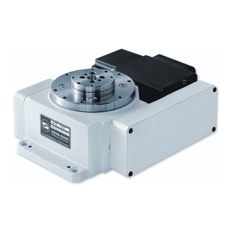
High Torque Rotary Unit
SW140

Document: Operating manual
Document version: Mechanical system documentation
Valid for: High Torque Rotary Unit
Type: SW140
Revision R07-2011
This document has been prepared by
WEISS GmbH, Siemensstrasse 17, D-74722 Buchen
Service
Tel: +49 6281 52080
www.weiss-gmbh.de
© WEISS GmbH
All rights in this document are the copyright of WEISSGmbH. This document may not be copied or reproduced, in
whole or in part, without the written permission of WEISS GmbH. This document is only intended for the user of
the product described and may not be passed on to third parties, in particular competitors.
Revisions
Date Revision Chapter Reason
15.10.2010 R10 - 2010 All Created
15.07.2011 R07 - 2011 2, 4, 5, 6, 7, 10 Supplement

WEISS
High Torque Dreheinheit SW140 R10-2010
3/36
List of contents
1. Introduction ........................................................................................................... 5
1.1. Definition ....................................................................................................... 5
1.2. Correct use ................................................................................................... 5
1.3. Incorrect use ................................................................................................. 5
1.4. Laws / EC Directives / Norms ....................................................................... 5
1.5. EC Declaration .............................................................................................. 6
1.6. System-dependant documentation ............................................................... 6
1.7. Operating manual ......................................................................................... 7
1.8. Guarantee and liability .................................................................................. 8
2. Safety ..................................................................................................................... 9
2.1. Fundamental safety instructions ................................................................... 9
2.2. Safety equipment for the machine .............................................................. 10
2.3. Residual hazards ........................................................................................ 11
3. Product description ............................................................................................ 12
3.1. Structure ..................................................................................................... 12
3.2. Function ...................................................................................................... 13
3.3. Technical data ............................................................................................. 13
3.4. Electrical connections ................................................................................. 16
4. Transportation ..................................................................................................... 19
4.1. Transportation damage ............................................................................... 19
4.2. Intermediate storage ................................................................................... 19
5. Installation ........................................................................................................... 20
5.1. Safety during installation ............................................................................. 20
5.2. Installation prerequisites ............................................................................. 20
5.3. Assemble machine ...................................................................................... 21
5.4. Installing the safety equipment ................................................................... 21
5.5. Instructions on disposal of packaging material ........................................... 21
6. Commissioning ................................................................................................... 22
6.1. Safety during commissioning ...................................................................... 22
6.2. Initial commissioning ................................................................................... 23
6.3. Recommissioning ........................................................................................ 23
7. Operation ............................................................................................................. 24
7.1. Safety during operation ............................................................................... 24
7.2. Operating the machine ................................................................................ 24
7.3. Operating personnel workstations .............................................................. 24
8. Malfunctions ........................................................................................................ 25
8.1. Safety when remedying malfunctions ......................................................... 25
8.2. Errors / Cause / Remedy ............................................................................ 25
8.3. Customer Service ....................................................................................... 25
9. Maintenance ........................................................................................................ 26
9.1. Safety during maintenance ......................................................................... 26
9.2. Maintenance work ....................................................................................... 27
9.3. Inspections .................................................................................................. 27
9.4. Maintenance ............................................................................................... 27
9.5. Repair ......................................................................................................... 27
10. Decommissioning / Dismantling / Disposal ...................................................... 28
10.1. Safety during decommissioning and dismantling ........................................ 28
10.2. Decommissioning ........................................................................................ 28
10.3. Dismantling and disposal ............................................................................ 29
11. Service and spare parts ...................................................................................... 30
11.1. Ordering spare parts ................................................................................... 30
12. Appendix .............................................................................................................. 31
12.1. Personal notes ............................................................................................ 33
1
2
High Torque Dreheinheit SW140 R10-2010
4/36
WEISS
Illustration indexGeneral view of the rotary unit ...................................................................................... 12
Example of a type plate ................................................................................................. 14
Installation positions ...................................................................................................... 14
Plug-in connections ....................................................................................................... 16
1
2

WEISS
High Torque Dreheinheit SW140 R10-2010
5/36
Introduction
1.1 Definition
1
1Introduction
1.1 Definition
The High Torque Rotary Unit is a model with a direct engine and absolute rotary encoder
for fast, precise and highly dynamic rotary, pivot and gripping movements.
The High Torque Rotary Unit is referred to as machine in the following text of this
operating manual.
1.2 Correct use
The machine is a noncomplete machine conforming to Directive 2006/42/EC,
Article1gand2g.
The machine is designed for integration in other machines, in other incomplete machines
or equipment or for connection to these.
It may only be used within the limitations defined in the order characteristics.
Commissioning is forbidden until the conformity of the product in which the machine is
installed with Directive 2006/42/EC and all other Directives governing use has been
determined and confirmed.
Observance of the accompanying documentation and adherence to maintenance
regulations are also component parts of correct use.
1.3 Incorrect use
Any use of the machine above or beyond the directions for correct use is regarded as
incorrect and prohibited.
The machine must not be subjected to loads that exceed the maximum limits.
The machine is not suitable for use
•
in wet or damp environments of any kind (water, oils, acids, steam or vapours, etc.).
•
in an environment with gases or radiation.
•
in potentially-explosive atmospheres.
•
in environments which contain swarf.
1.4 Laws / EC Directives / Norms
The machine is designed and constructed to conform to
•
applicable laws
•
Directive 2006/42/EC (Machinery Directive)
•
Low Voltage Directive, 2006/95/EC
•
EMC Directive 2004/108/EC
•
and the harmonised standards that we have cited
and meets state-of-the-art technological standards in terms of its construction.

High Torque Dreheinheit SW140 R10-2010
6/36
WEISS
Introduction
1.5 EC Declaration
1
1.5 EC Declaration
An EC Declaration as specified by Directive 2006/42/EC (Machinery Directive) is
included with each machine at delivery.
The text of this EC Declaration is as follows:
WEISS GmbH Sondermaschinentechnik
Siemensstrasse 17
D-74722 Buchen, Germany
Declaration of incorporation of partly completed machinery
in accordance with EC Machinery Directive 2006/42/EC, Annex II B
Prohibition of commissioning
We hereby declare that the machine called High Torque Rotary Unit SW140 is intended
for the installation into another machine or is to be assembled with other machines to a
machine in terms of the directive 2006/42/EC.
Commissioning is prohibited until it has been established that the machine into which the
aforementioned product should be installed satisfies the provisions of the EC Machinery
Directive, and that a Declaration of Conformity in accordance with EC Machinery Direc-
tive 2006/42/EC, Annex II A has been issued.
1.6 System-dependant documentation
In addition to this manual, further documents are required to ensure safe operation of this
machine. The specifications stated in these documents are to be observed.
For control system by WEISS-GmbH:
•
Operating manual WAS.indexer Control SW140
•
Operating manual WAS.handling Windows programme

WEISS
High Torque Dreheinheit SW140 R10-2010
7/36
Introduction
1.7 Operating manual
1
1.7 Operating manual
This operating manual is a translation of the original operating manual and is part
of the scope of delivery.
We reserve the right to undertake modifications resulting from further technological
development which diverge from the data and illustrations contained in this operating
manual.
The operating manual and the associated valid documentation are not subject to an auto-
matic revision service.
Information on the respective current edition can be obtained from the manufacturer.
Local regulations must be heeded.
This operating manual describes handling of the machine and contains important instruc-
tions and information to assist you in correct use of the machine.
The operating manual is designed for trained technical personnel and instructed persons.
It should be kept at the location of use of the machine at all times and read, understood
and applied by all persons entrusted with work on or with the machine.
Safety instructions in individual chapters should be observed.
1.7.1 Explanation of safety instructions in this manual
This manual contains instructions which you should observe for your personal safety and
to avoid material damage.
Safety instructions for yourpersonal safety are highlighted by a sign containing a warning
triangle and signal word. The associated text describes the hazard involved, avoidance
options and the consequences of a failure to heed the safety instruction.
General instructions or instructions relating to possible material damage are highlighted
by a sign without a warning triangle.
They are, depending on the degree of risk involved, illustrated as follows:
A warning triangle with the signal word DANGER
indicates an immediate hazardous situation which, if
not avoided, will lead to fatalities or grievous injuries.
A warning triangle with the signal word WARNING
indicates an potential hazardous situation which, if
not avoided, can lead to fatalities or grievous injuries.
A warning triangle with the signal word CAUTION
indicates an potential hazardous situation which, if
not avoided, can lead to light or medium injuries.
A sign with the signal word NOTICE indicates
potential material damage or provides additional
information which should be observed when
operating the machine.

High Torque Dreheinheit SW140 R10-2010
8/36
WEISS
Introduction
1.8 Guarantee and liability
1
1.7.2 Legend
In these manual images, symbols and abbreviations with the following meaning are used
for clarity:
1. Marks a numbered list.
a) Marks the second level of a numbered list.
•
Marks a list.
`Marks the second level of a list.
The book symbol before a section of text indicates additional applicable docu-
ments.
L
The information symbol before a section of text marks an additional note or an
important tip for use.
1.7.3 Figures
The figures used are examples. There may be differences between the illustrations and
the actual delivery.
1.7.4 Index of valid pages
Pages of this operating manual including the title page: 36
1.8 Guarantee and liability
The machine is covered by a guarantee of 24 months without shift limitations.

WEISS
High Torque Dreheinheit SW140 R10-2010
9/36
Safety
2.1 Fundamental safety instructions
2
2Safety
2.1 Fundamental safety instructions
2.1.1 Operator‘s obligation to exercise diligence
This machine conforms to state-of-the-art technological standards and ensures a maxi-
mum level of safety.
However, this level of safety can only be attained under operating conditions if all measu-
res necessary for this have been taken. The operator‘s obligation to exercise diligence
includes planning of these measures and the inspection of their realisation.
The operator must ensure that
•
the machine is only used as intended.
•
the machine is only operated in faultless, functional condition and mechanical and
electrical safety devices are present.
•
required personal protective clothing is provided for and used by operating, mainte-
nance and repair personnel.
•
the operating manual and all other applicable documentationis maintained at all times
in legible condition and is accessible at the implementation site of the machine.
Ensure that all personnel who must execute activities tasks on the machine can
access the operating manual at all times.
•
only adequately qualified and authorised personnel maintain and repair the machine.
•
such personnel are instructed regularly in all questions concerning occupational
safety and environmental protection, including the operating manual and safety
instructions contained therein.
•
all safety instructions and warnings affixed to the product are not removed and must
remain legible.
•
national accident prevention guidelines and company-internal guidelines are complied
with.
•
VDE regulations are complied with.
•
the EMC legislation is complied with during installation.

High Torque Dreheinheit SW140 R10-2010
10/36
WEISS
Safety
2.2 Safety equipment for the machine
2
2.1.2 Requirements to be met by personnel
It is imperative that the following safety instructions be observed during all operations
involving the machine. This ensures avoidance of life-threatening injuries, machine
damage, other material damage and environmental damage.
Personnel must ensure that
•
trainees are initially permitted to only work on the machine under the supervision of an
experienced person.
•
all personnel who maintain the machine read the operating manual and confirm with
their signature that they have understood the operating manual.
•
unauthorised persons are not in the vicinity of the machine when tasks are being per-
formed.
•
supplemental to the operating manual the operating instructions as specified in labour
protection legislation and work equipment use legislation are complied with.
•
the operator or supervisory personnel are informed in the event of malfunction.
•
required personal protective clothing is used.
The following work described in this operating manual should only be realised by quali-
fied personnel:
•
Transport
•
Installation
•
Commissioning
•
Maintenance
2.2 Safety equipment for the machine
The operator is responsible for ensuring that a suitable safety concept is developed and
applied for the safe operation of the machine.
The operator must take all measures to protect his personnel against injury by the
machine.
These include:
•
Safety housing with monitored safety door
•
Emergency stop circuit
•
Light barriers or switch mats
•
Warning indicators

WEISS
High Torque Dreheinheit SW140 R10-2010
11/36
Safety
2.3 Residual hazards
2
2.3 Residual hazards
Missing safety equipment
Operation without safety installations is dangerous. The operator is responsible for the
realisation of a suitable safety concept. The operator must provide for sufficient safety
measures such as protective grating, light grids, emergencystop button, covers, warning
notices, etc. Operation without safety equipment is prohibited. Injuries caused by squee-
zing or pulling in.
Missing danger signs
Damaged or illegible danger signs no longer fulfil their purpose. Make sure the danger
signs are complete and legible. Replace damaged danger signs.
Danger of explosion
Danger of explosion during operation in a potentially explosiveatmosphere. Operation in
a potentially explosive atmosphere is prohibited according to correct use. Only correct
use is permitted. Injuries caused by an explosion.
Incorrect spare pats / mounting of ancillary equipment
The use of incorrect spare parts orthe mounting of unauthorised ancillary equipment can
lead to subsequent damage with the risk of injury. Only use spare parts from our spare
parts list or spare parts we have approved. The mounting of ancillary equipment must be
coordinated with us. Injury of persons due to subsequent damage.
Impermissible modifications
Impermissible modifications can lead to subsequent damage with risk of injury. Modifica-
tions on the machine are prohibited. Injury of persons due to subsequent damage.
Electric shock
Power and control connections may still conduct electricity after the machine has been
deactivated and is stationary. Energised capacitors inside the servo amplifier may still be
charged, despite the power supply being deactivated. Work on electrical equipment
should only be realised by skilled electrical personnel and under observance of specifica-
tions in the electrical operating manual. Electrical connections for the machine should
onlybeloosenedorpluggedin whenthepowersupplyisdeactivatedandsecuredagainst
reactivation. The status of capacitor charging should be measured prior to working on
machine electrical equipment. The procedure for measuring charges is described in the
electrical operating manual. Touching energised components can lead to serious or even
fatal injuries.
Squeezing or pulling in
The shaft of the machine turns at a very high speed. Extremities can be crushed or
pinched when interfering with the motion sequence. Never put hands into the work area
of the machine. Injuries caused by squeezing.

High Torque Dreheinheit SW140 R10-2010
12/36
WEISS
Product description
3.1 Structure
3
3 Product description
3.1 Structure
The optionally programmable, highly dynamic High Torque Rotary Unit consists of a solid
Base body [A] made of aluminium with the electrical connections and the motor shaft.
The motor shaft can be designed as standing shaft [B] or as hollow shaft [C].
The machine can be certified for sterile room usage.
Every machine can be delivered in different constructions.
The existing holes in the base body and different flange shapes allow versatile options of
fixing.
Operator installations can be powered over the shaft .
The electric connections for the motor, rotary encoder and optional holding brake are
created with plugs.
A absolute measuring system is used as a measuring system. The measuring system
used depends on the order.
The following parameters of the machine are variable:
•
size
•
length
•
rotary encoder
•
holding brake
•
shaft
•
flange
Fig. 1: General view of the rotary unit
A A
B C
i i i i i i i i i i i i i i i i i

WEISS
High Torque Dreheinheit SW140 R10-2010
13/36
Product description
3.2 Function
3
3.2 Function
The engine is controlled via a servo amplifier and turns, accelerates or delays the rotary
disc of the machine. The The shaft can be operated left-running, right-running or oscilla-
ting.
A high level of positional accuracy and repeat accuracy are achieved through the integra-
ted measuring system.
In stillstand, the shaft can be held in its position by the optional holding brake. The brake
force is created with springs. The brake is lifted by electromagnetic control and closes
automatically if the voltage is turned off or in case of power outage.
3.3 Technical data
3.3.1 Scope of delivery
The scope of delivery of the machine depends on the order involved. Please refer to the
ordering information or order characteristics for individual components.
3.3.2 Sound level
The A-weighted emission sound pressure level do not exeed the allowable peak.
High Torque Rotary Unit SW140
Nominal torque 15 Nm
max. Torque 36 Nm
max. speed 600/min
Nominal voltage 230 V
Nominal current 3,1 A
Peak current 7,5 A
Holding torque of the brake 15 Nm
Temperature monitoring PTC
Heat class F
Heat class of the isolation system according to
EN600341
Concentricity 0,01 mm
Axial run-out 0,01 mm
Weight 2.5 kg
Weight with standard encoder and without brake
Measuring system Interface Sick-Stegmann Hyperface
Precision SEK90: ± 130"
Measuring system Interface Heidenhain EnDat
Precision ECN113: ± 20"
ECN225: ± 10"
i i i i i i i i i i i i i i i i i

High Torque Dreheinheit SW140 R10-2010
14/36
WEISS
Product description
3.3 Technical data
3
3.3.3 Type plate
The type plate is fitted to the housing of the machine and contains the details described
in the illustration.The illustrated type plate is merely an example of any machine and
is not identical to the actual type plate of the described product.
A second type plate is included in the scope of delivery. This second plate can be moun-
ted at a clearly-visible location on the machine to allow viewing of performance data if the
type plate fitted by the manufacturer is concealed by any other structures.
Fig. 2: Example of a type plate
3.3.4 Ambient conditions
3.3.5 Installation positions
Permissible installation positions for the machine are:
•
horizontal and vertical at any angles.
Fig. 3: Installation positions
Additional barcode serial number
Type
Serial Number
Motor speed
Nominal torque
Rotary encoder
Year of construction
Weight
www.weiss-gmbh.de
WEISS
type
motor
serial
weight
motor
year
SWXXXXXX - X
SWXXXXXX
XXXXXXX
XX kg
XXXX
encoder
XXX UPM
X,X Nm
Humidity 5 % to 95 %, non-condensing
Allowable temperature range Storage: +5 °C to +55 °C
Operation: +15 °C to +45 °C
Environment It is not permissible to use the machine in environ-
ments that contain abrasive dusts.
i i i i i i i i i i i i i i i i i

WEISS
High Torque Dreheinheit SW140 R10-2010
15/36
Product description
3.3 Technical data
3
3.3.6 Dimensions
3.3.6.1 High Torque Dreheinheit SW140
X = Option with customer motor shaft
X
28
28
50
50
H7
H7
19,5
19,5
140
140
2,5
2,5
104
104
12
12
11
11
93
93
h6
h6
A
A
76
76
25,6
25,6
2x
2x
6
6
H7
H7
x12
x12
6x M6x12
6x M6x12
4x
4x
9
9
130
130
h6
h6
116
116
±0,1
0,1
116
116
±0,1
0,1
Lk
Lk
38
38
±0,1
0,1
8x M5
8x M5
50
50
LK
LK
65
65
±0,01
0,01
45
45
°
45
45
°
28
28
k6
k6
140
140
50
50
61,5
61,5
Option
Option
Measurement table: Dimensions in mm
SW
A
Sick Stegmann Heidenhain
SEK90 ECN113 ECN225
with holding brake with holding brake with holding brake
140 154 213,8 185 241 185 241
i i i i i i i i i i i i i i i i i

High Torque Dreheinheit SW140 R10-2010
16/36
WEISS
Product description
3.4 Electrical connections
3
3.4 Electrical connections
The servo amplifier and the ready-made electric cables are included in delivery when the
machine is supplied with the electrical package.
3.4.1 Plug-in connections
The plugs for motor cable [A] and measuring system [B] are mounted in an easily acces-
sible manner on the casing of the machine.
Fig. 4: Plug-in connections
A AB B
i i i i i i i i i i i i i i i i i

WEISS
High Torque Dreheinheit SW140 R10-2010
17/36
Product description
3.4 Electrical connections
3
3.4.2 Connector pin assignment
3.4.2.1 Connection motor
⇐ to the drive Pin assignment
InterContec M25 BEGA 125 MR 13 00 0006 000
4
1
2
3
A
B
C
D
U
V
W
PE
B +
B -
T +
T -
3
A
B
CD
2
4
1
A
A
i i i i i i i i i i i i i i i i i

High Torque Dreheinheit SW140 R10-2010
18/36
WEISS
Product description
3.4 Electrical connections
3
3.4.2.2 Connection encoder
⇐ to the drive Pin assignment
InterContec M25 D_AEGA052MR04000201000
10
7
12
8
4
1
9
2
3
5
6
11
GND
+7...12V
n.c
n.c
+COS
REFCOS
+SIN
REFSIN
Data -
Data +
n.c
n.c
1
2
9
10
P8
7
12 6
11
345
B
B
i i i i i i i i i i i i i i i i i

WEISS
High Torque Dreheinheit SW140 R10-2010
19/36
Transportation
4.1 Transportation damage
4
4 Transportation
4.1 Transportation damage
The delivery should be inspected for damage immediately after receipt. The contents of
the delivery should be checked for damage if damage to the packaging is detected,
which could indicate damage to the contents. Details of the scope of delivery are provi-
ded in Chapter 3.3.1.
Damage detected should be immediately reported to and confirmed by the transportation
company.
4.2 Intermediate storage
The storage conditions detailed in the table should be observed if intermediate storage
over a longer period of time is planned.
The machine must be protected against impermissible strains (mechanical strain,
temperature, humidity, aggressive atmospheres) during transport and when being
stored.
Climatic
zone Packaging Storage location Storage duration
All Packed in contai-
ners
With moisture
absorbers and
humidity indicator
sealed in film
Protect against
insect damage and
mould formation
through chemical
treatment
Roofed over
Protected against rain
Not exposed to vibrations
Max. 3 years with
regularinspectionof
packaging
Open
Roofed over and sealed at a
constant temperature and air
humidity (5 °C < T < 60 °C,
50% relative humidity)
No sudden temperature fluc-
tuation and controlled ventila-
tion with filter (free of dirt and
dust)
No aggressive vapours and no
vibrations
Protected against insect
damage
2 years and longer
with regular inspec-
tion. Check for cle-
anliness and
machine damage
during inspection.
Check that anticor-
rosion protection is
unspoiled.

High Torque Dreheinheit SW140 R10-2010
20/36
WEISS
Installation
5.1 Safety during installation
5
5 Installation
5.1 Safety during installation
5.2 Installation prerequisites
Check prior to installation whether the dimensions of the installation site and building
conditions correspond to the necessary prerequisites and measurement specification in
the drawing documents.
Particularly ensure that:
•
The supporting floor is level and rigid.
•
The dimensions of the supporting structure at the installation location must be suf-
ficient to withstand the dynamic forces that occur.
5.2.1 Installation preparation
•
Open the packaging unit prior to the assembly and remove the machine from the
packaging unit.
•
The customer's bores must be made based on the hole pattern in Chapter 3.3.6.
•
The attachment screws must be at hand.
5.2.2 Operating media / Auxiliary media / Tools
The following are required for installation of the machine:
•
One set of spanners
•
One torque wrench
•
One set of screwdrivers
•
Screw securing agent (e.g. Loctite ® 243)
•
Screws which are at least have a property class of 8.8
Injuries caused by incorrect installation.
Thedimensionsof thesupportinggroundandfasteningequipment mustsufficient, sothat
they can withstand the stresses produced during operation.
Work should only be assigned to auxiliary personnel by company installation personnel.
Create a proper electrical grounding.
Table of contents
Other WEISS Industrial Equipment manuals

WEISS
WEISS Pick-O-Mat PM1100 User guide

WEISS
WEISS HL50 User manual

WEISS
WEISS CR1000C User manual

WEISS
WEISS CR2000C User manual

WEISS
WEISS TR0750A User manual

WEISS
WEISS CR1300C User manual

WEISS
WEISS TC Series User manual

WEISS
WEISS ST Series User guide

WEISS
WEISS WAS.handling User manual

WEISS
WEISS NR Series User manual