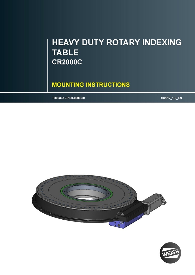
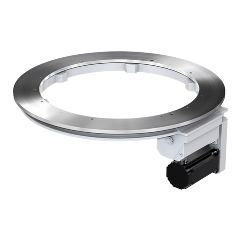
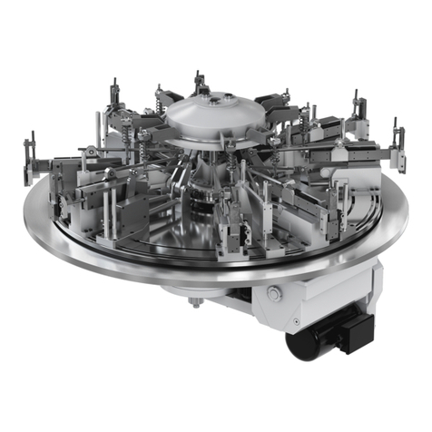
WEISS TC Series User manual

Rundschalttische TC
Rotary Indexing Tables TC
Betriebsanleitung
Operating Instructions

2WEISS GmbH 03/2002
- Für Ihre Notizen -
- For your Notes -

WEISS GmbH 03/2002 3
Lesen Sie diese Betriebsanleitung sorgfältig
durch und bewahren Sie sie zum späteren
Nachschlagen gut auf.
Machen Sie sich insbesondere als erstes mit
den Sicherheitsvorschriften vertraut.
Stand: März 2002
WEISS GmbH
Sondermaschinentechnik
Siemensstrasse 17
D-74722 Buchen/Odw.
Tel.: +49 (0) 6281 / 5208-0
Fax: +49 (0) 6281 / 9150
eMail: info@weiss-gmbh.de
Internet: http://www.weiss-gmbh.de
Technische Änderungen vorbehalten.
Please study these Operating Instructions
very carefully and keep them as reference.
First of all please familiarize yourself with the
safety instructions.
Release: March 2002
WEISS GmbH
Sondermaschinentechnik
Siemensstrasse 17
D-74722 Buchen/Odw.
Tel.: +49 (0) 6281 / 5208-0
Fax: +49 (0) 6281 / 9150
eMail: info@weiss-gmbh.de
Internet: http://www.weiss-gmbh.de
We reserve the right to change or discontinue
specifications without prior notice.

4WEISS GmbH 03/2002
Inhaltsverzeichnis
1 Sicherheitsvorschriften 7
1.1 Bestimmungsgemässe Verwendung 7
1.2 Erläuterung der verwendeten Symbole 7
1.3 Sicherheitsbestimmungen 7
2 Beschreibung der Rundschalt-
tische 11
2.1 Mechanik 11
2.2 Antrieb 12
2.3 Einbaulagen der Rundschalttische und
Anbau des Motors (Antriebslage) 13
2.4 Positionsnocken/Näherungsschalter 15
2.5 Dauermagnetbremse 16
2.6 Verändern der Schaltzeit 17
3 Steuern der Rundschalttische 19
3.1 Allgemeine Funktionsweise 19
3.2 Steuern mit der Steuerkarte TS 002 E 20
3.3 Steuern mit der Steuerung EF xxx 22
3.4 Steuerungsablauf mit Fremdsteuerung
(SPS) 24
3.5 Anschluss von Steuerung,
Motor und Bremse 26
Bremsmotor Normalbetrieb (24V Bremse) 26
Bremsmotor Pendelbetrieb (24V Bremse) 27
Schaltungsbeispiel für
langsamlaufende Rundschalttische 29
Schaltungsbeispiel für
schnelllaufende Rundschalttische 30
Anschluss der Steuerung EF 037/1 31
Anschluss der Steuerungen
EF 150/3, EF 220/3, EF 300/3 32
4 Inbetriebnahme 33
4.1 Sicherheitsbestimmungen 33
4.2 Elektrische Vorbereitungen 34
4.3 Entlüftungsschraube/Verschlussstopfen 35
4.4 Allgemeines Vorgehen zur Inbetrieb-
nahme 36
4.5 Montage von Zusatzschalttellern 36
Table of Contents
1 Safety instructions 7
1.1 Intended Use 7
1.2 Explanation of Symbols 7
1.3 Safety Regulations 7
2 Description of the Indexers
11
2.1 Mechanics 11
2.2 Drive 12
2.3 Mounting Position of Indexer and
drive Position 13
2.4 Cam & Limit Switch 15
2.5 Magnetic Brake 16
2.6 Change of Index Time 17
3 Control of Indexers 19
3.1 Function in general 19
3.2 Control with the Controller Card TS 002 E 20
3.3 Control with the Controller Card EF xxx 22
3.4 Control Sequence with PLC 24
3.5 Control, Drive Motor and Brake Wiring 26
Brake Motor Normal Operation 26
Brake Motor Reciprocating Operation 27
Example for slow cycling indexing tables 29
Example for fast cycling indexing tables 30
Wiring of Controller Card EF 037/1 31
Wiring of Controller Cards
EF 150/3, EF 220/3, EF 300/3 32
4 Start-Up 33
4.1 Safety regulations 33
4.2 Electrical Preparations 34
4.3 Breather Valve 35
4.4 General Start-Up 36
4.5 Installation of Tooling Plate 36

WEISS GmbH 03/2002 5
5 Wartung 37
5.1 Einstellung der Bremse bei Brems-
motoren 37
5.2 Bremse ersetzen 39
5.3 Motor ersetzen 40
5.4 Zahnriemen ersetzen 42
5.5 Näherungsinitiator ersetzen 43
5.6 Schmierstoffe 43
6 Störungsbehebung 45
6.1 Störungsbehebung bei der
Rundschalttischsteuerung TS 002 E 45
Fehleranzeige "Position überfahren" 45
Fehleranzeige "Motor Überlast" 46
Fehleranzeige "Kurzschluss" 47
6.2 Störungsbehebung bei der
Rundschalttischsteuerung EF xxx 48
7 Ersatzteile 49
8 Entsorgung und Recycling 51
A Anhang 53
A.1 Zusatzinformationen
Ringrundschalttische TR und NR 53
A.2 Zusatzinformationen
Ringrundschalttisch NR 56
5 Maintenance 37
5.1 Adjustment of Brake on Brake-Motor 37
5.2 Replace Brake 39
5.3 Replace motor 40
5.4 Replace Timing Belt 42
5.5 Replace Limit Switch 43
5.6 Lubrication 43
6 Troubleshooting 45
6.1 Troubleshooting Control Card TS 002 E 45
Fault Message “Position Over Run” 45
Fault Message “Motor Overload” 46
Fault message “Electrical Short” 47
6.2 Troubleshooting the Control CArd EF xxx 48
7 Spare Parts 49
8 Disposal and Recycling 51
A Appendix 53
A.1 Additional information
Indexing Rings TR and NR 53
A.2 Additional information
Indexing Ring NR 56

6WEISS GmbH 03/2002
- Für Ihre Notizen -
- For your Notes -

WEISS GmbH 03/2002 7
1 Sicherheitsvorschriften
1.1 Bestimmungsgemäße Verwendung
Die Rundschalttische der TC-Typenreihe sind
ausschließlich für getaktete Drehbewegungen
einer Nutzlast bestimmt, welche bei der Mani-
pulation nicht personen-, sach- und umwelt-
gefährdend reagieren kann. Zudem dürfen die
Rundschalttische einzig im Rahmen der in der
vorliegenden Betriebsanleitung und in den
Verkaufsunterlagen angegebenen Spezifika-
tionen eingesetzt werden. Eine andere oder
darüberhinausgehende Benützung gilt als
nicht bestimmungsgemäss. Zur bestimmungs-
gemässen Verwendung gehört auch das
Beachten der Betriebsanleitung und das
Einhalten der vom Hersteller
vorgeschriebenen Wartungs- und
Instandsetzungsvorschriften.
1.2 Erklärung der verwendeten Symbole
WARNUNG
In dieser Betriebsanleitung haben wir alle
Stellen, die Ihre persönliche Sicherheit
betreffen mit diesem Symbol versehen.
HINWEIS
Unter diesem Symbol erhalten Sie Hinweise
für den sachgerechten Umgang mit dem
Rundschalttisch. Das Nichtbeachten dieser
Hinweise kann zu Störungen am
Rundschalttisch oder der Umgebung führen.
1.3 Sicherheitsbestimmungen
Vor der Inbetriebnahme des
Rundschalttisches ist die Betriebsanleitung
aufmerksam zu lesen.
Der Rundschalttisch darf erst in Betrieb
genommen werden, wenn die Gesamtanlage,
in welche der Rundschalttisch integriert ist,
sowie die Steuerung – speziell das
Sicherheitssystem – der Maschinenrichtlinie
98/37/EG entspricht!
1 Safety Instructions
1.1 Intended Use
The Model TC indexer is for the exclusive
rotational indexed motion of a payload, which
during operation shall not damage persons,
goods or the environment. The indexer shall
only be used within the limits of these
Operating Instructions and within the
specifications that are included in the sales
contract. The use beyond theses definitions
is determined as outside the limits of
“Intended Use”. Part of the “Intended Use” is
also adherence to the “Operational
Instructions”, “Maintenance Instructions” and
“Trouble Shooting Instructions”.
1.2 Explanations of Symbols
WARNING
Each area, which concerns your personal
safety, shows this symbol.
NOTE
This symbol will draw your attention to the
correct use of the indexer. Non-adherence
can cause trouble for the indexer or the
environment.
1.3 Safety Regulations
Please read the Operation Manual carefully
before Start-Up
The indexer can only be used after the
complete system into which the indexer is
integrated adheres to the control and safety
regulations of “Machine Regulations
98/37/EG”

8WEISS GmbH 03/2002
WARNUNG
· Drehteller mit hohem Drehmoment!
· Quetschungen oder Verlust von
Gliedmaßen!
· Nie in den Arbeitsbereich des
Drehtellers und seiner Aufbauten
hineingreifen!
WARNUNG
Im Normalbetrieb sind ausreichende
Schutzvorrichtungen, z.B. Schutzgitter,
Abdeckungen, Lichtvorhänge oder
Trittmatten zu installieren, um das
Bedienpersonal vor Verletzungen durch
die Mechanik zu schützen.
Die einschlägigen
Unfallverhütungsvorschriften sowie die
sonstigen allgemein anerkannten
sicherheitstechnischen und arbeitsmedizini-
schen Vorschriften sind einzuhalten.
Unzulässige Veränderungen und die Verwen-
dung von Ersatzteilen und
Zusatzeinrichtungen, die nicht vom Hersteller
empfohlen werden, können Verletzungen von
Personen oder Sachschäden hervorrufen.
WARNUNG
Vor Einstellungs- und Wartungsarbeiten
ist der Antrieb spannungslos zu schalten
und vor Wiederanlauf zu sichern!
Solche Arbeiten – ob an der Mechanik oder
der Steuerung des Rundschalttisches –
dürfen nur von geschultem Fachpersonal
durchgeführt werden. Geschultes
Fachpersonal sind Personen, die mit der
Aufstellung, Montage, Inbetriebsetzung und
Betrieb des Rundschalttisches vertraut und
über die Gefahren unterrichtet sind.
WARNUNG
Es ist in keinem Fall möglich, den
Rundschalttisch von Hand in eine der
möglichen Verriegelungspositionen zu
drehen!
WARNING
· High torque tooling plate!
· Danger of injury or loss of limbs
· Never reach into the work area of the
tooling plate including its tooling!
WARNING
Use protective devices such as
enclosures, covers, light curtains or tread
mats to protect the operator from injury.
Apply the standard rules and regulations for
prevention of accidents as well as health and
safety recommendations.
In all cases any protective devices must
comply with the statutory safety requirements
prevailing in the country of the end user.
Unauthorized modifications and the use of
parts and accessories that are not
recommended by the manufacturer could
cause injury or material damage.
WARNING
Disconnect the drive before set-up or
maintenance work.
Trained and authorized technicians shall only
perform this type of work on the indexer or its
controls. Trained technicians are persons
who are familiar with the installation, set-up
and use of the indexer and who have been
instructed about the dangers involved.
WARNING
It is not possible to turn the indexer by
hand in one of the dwell periods.

WEISS GmbH 03/2002 9
WARNUNG
Die Rundschalttische dürfen nicht in einer
explosionsgefährdeten Umgebung eingesetzt
werden.
Jeder sicherheitsbedenkliche Einsatz eines
Rundschalttisches ist zu unterlassen!
Die Rundschalttische dürfen weder während
der Lagerung noch während des Betriebes
Flüssigkeiten ausgesetzt sein.
HINWEISE
Die Elektromotoren sind grundsätzlich vor
Überlastung zu schützen. Wir empfehlen den
Einsatz eines Motorschutzschalters mit
elektromagnetischem Schnellauslöser. Als
zusätzliche Absicherung haben unsere
Steuerungen TS 002 E und EF-xxx eine
Zykluszeitüberwachung. Sollten Sie diese
Steueren nicht verwenden, so installieren Sie
bitte in Ihrer Steuerung eine Zykluszeitüber-
wachung, die nach Auslösen eines Start-
signales den Motor abschaltet, wenn nach ca.
doppelter Drehbewegungszeit keine Fertig-
meldung durch den induktiven Näherungs-
schalter "P" erfolgt.
Bei Nichteinhaltung dieser Empfehlungen
können wir keine Garantie für
Motorschäden übernehmen.
Vor der Inbetriebnahme des Rundschalt-
tisches Verschlussstopfen der Entlüftungs-
schraube entfernen (siehe Kapitel 4.3).
WARNUNG
Transportieren Sie den Rundschalttisch nur
mit einem Hebezeug, welches für das
entsprechende Gewicht ausgelegt ist (siehe
Gewichtstabelle im Kapitel 4.1). Verwenden
Sie für das Befestigen des Rundschalttisches
am Hebezeug Ringschrauben, die der
Belastung sicher standhalten.
Für TC 120 bis TC 320 genügen zwei Ring-
schrauben, ab TC 500 sind drei
Ringschrauben einzusetzen.
Befestigen Sie die Ringschrauben in den Ge-
winden des Drehtellers (siehe auch Kapitel
4.1).
WARNING
The indexers cannot be used in an explosion
hazard environment.
The indexer shall not be used in applications
where safety is compromised.
The indexers shall not be exposed to any
liquids during storage or in use.
NOTES
The drive motors have to be protected against
overload. We recommend the use of a
protective motor switch with a magnetic quick-
action circuit breaker. Our control cards
TS 002E and EF-xxx have a cycle time control
as an added safety feature. In case you don’t
use these control cards you should program a
cycle time control in your PLC. The motor
should be disconnected if the limit switch “P”
is not made after a period of double the index
time since the start signal.
We will decline the warranty for the motor
if this recommendation has not been
followed.
Before start-up remove the plug from the
breather valve.
WARNING
For transportation use only hoists which are
designed for the weight of the indexer. (See
weight table in chapter 4.1). Use eyebolts,
which are strong enough.
Use 2 eyebolts for indexer models TC 120 to
TC 320, use 3 eye bolts for models TC 500
and above.
The dial plates have the correct tapped holes
for the eyebolts (refer to chapter 4.1).
10 WEISS GmbH 03/2002
WARNUNG
Arbeiten an der elektrischen Installation
dürfen nur von einer Elektrofachkraft oder von
unterwiesenen Personen unter Leitung und
Aufsicht einer Elektrofachkraft ausgeführt
werden. Die fachspezifischen Sicherheits-
vorschriften sind zu befolgen.
WARNUNG
Dem Antriebsmotor des Rundschalttisches
sind in jedem Fall
r geeignete NOT-AUS-Einrichtungen
nach EN 60 204-1 (Einrichtungen für
Handlungen im Notfall)
r ein Motorschütz sowie
r ein Motorschutzschalter
vorzuschalten.
Im NOT-AUS-Betrieb muss die
Motorspannung unterbrochen werden.
Die 24V-DC-Versorgungsspannung der
Steuerkarte braucht dagegen nicht
unterbrochen zu werden. In diesem Falle
muss jedoch der RESET/STOP-Eingang der
Steuerkarte deaktiviert werden (Klemme 2:
low-Pegel), um erstens die Bremse zu
schließen und zweitens die zwangsläufig
auftretende Fehlermeldung "Motorüberlast" zu
unterdrücken, falls die
Motorspannungsabschaltung mitten im Zyklus
erfolgt.
Sollten Sie Fragen zum Rundschalttisch
haben – insbesondere auch Fragen zur
Sicherheit –, wenden Sie sich an folgende
Adresse:
WEISS GmbH
Sondermaschinentechnik
Siemensstrasse 17
D-74722 Buchen/Odw.
Tel.: +49 (0) 6281 / 5208-0
Fax: +49 (0) 6281 / 9150
eMail: info@weiss-gmbh.de
Internet: http://www.weiss-gmbh.de
Im Internet können Sie sämtliche Vertreter-
adressen abrufen.
WARNING
Only electricians or trained personal under
supervision of an electrician shall do the
electrical installation of the indexer. The
specific rules and regulations for electrical
installation are to be followed.
WARNING
The drive motor has to be connected to:
r An E-STOP switch (according to
EN 60-204-1)
r A motor contactor and
r A protective motor switch
In E-STOP the power has to be interrupted.
The 24VDC power for the control card does
not have to be interrupted. In this case the
RESET/STOP input of the control card has to
be deactivated (Connection 2, low level) to
activate the motor brake and to avoid the fault
message “Overload” in case the E-STOP
occurs during index.
For additional questions especially if they are
safety related please contact:
WEISS GmbH
Sondermaschinentechnik
Siemensstrasse 17
D-74722 Buchen/Odw.
Tel.: +49 (0) 6281 / 5208-0
Fax: +49 (0) 6281 / 9150
eMail: info@weiss-gmbh.de
Internet: http://www.weiss-gmbh.de
You will find all addresses of our
representatives on our web page.

WEISS GmbH 03/2002 11
2 Beschreibung der
Rundschalttische
2.1 Mechanik
Die Rundschalttische der TC-Typenreihe
werden von einem Zylinderkurvenschritt-
getriebe mit sinoiden Beschleunigungs- und
Bremsverhalten angetrieben. Dadurch wird
ein sehr weiches Anfahren und Abbremsen
erreicht.
Während der Drehphase des Rundtischtellers
rollen die Antriebselemente in der
Kurvenbahn der Antriebskurve (Rollreibung)
ab. In der Verriegelungsphase liegen zwei
Antriebsrollen vorgespannt an der
Antriebskurve an. Die Kurvenrollen sind
nadelgelagert.
2 Description of the Index
Tables
2.1 Mechanics
A cylindrical barrel cam with a sine type
acceleration and deceleration curve rotates
the index tables of the TC series. This allows
for a very soft start and stop operation.
During index the cam followers follow the
groove of the barrel cam in a rolling motion.
During dwell two cam followers touch the
groove under a preload. The cam followers
have needle bearings.
Fig. 2-1

12 WEISS GmbH 03/2002
2.2 Antrieb
Der Antrieb erfolgt standardmäßig für alle
Typen durch Drehstrombremsmotoren mit
24V- Gleichstrom-Bremse.
Der Motor läuft nur während der Drehphase
des Rundschalttisches und wird nach
Erreichen der Verriegelung ausgeschaltet.
Der Kraftfluss verläuft vom Motor über eine
Zahnriemenstufe und ein ein- oder
zweistufiges Zahnradgetriebe direkt auf die
Antriebskurve.
Bei sehr kurzen Bearbeitungszeiten oder
hohen Schalthäufigkeiten (>50/min) wird der
Standardbremsmotor durch einen
Bremsmotor mit selbstnachstellender
Bremse ersetzt (Kobold-Motor).
Als Sonderausführung existieren Drehstrom-
bremsmotoren mit 230V-Wechselstrom-
bremse.
Die technischen Daten der Motoren sind auf
der Auftragsbestätigung, dem Lieferschein
und der Rechnung aufgeführt.
HINWEIS
Die Elektromotoren sind grundsätzlich vor
Überlastung zu schützen. Wir empfehlen den
Einsatz eines Motorschutzschalters mit
elektromagnetischem Schnellauslöser. Als
zusätzliche Absicherung hat unsere
Steuerkarte TS 002 E eine
Zykluszeitüberwachung. Sollten Sie diese
Steuerkarte nicht verwenden, so installieren
Sie bitte in Ihrer Steuerung eine
Zykluszeitüberwachung, die nach Auslösen
eines Startsignales den Motor abschaltet,
wenn nach ca. dreifacher Drehbewegungszeit
keine Fertigmeldung durch den induktiven
Näherungsschalter "P" erfolgt.
Bei Nichteinhaltung dieser Empfehlungen
können wir keine Garantie für
Motorschäden übernehmen.
2.2 Drive
The standard drive is a 3-phase brake motor
with a 24VDC brake
The motor runs only during the index phase
and will be switched after reaching dwell.
The power is transmitted from the motor
through a timing belt via a one or two-step
gear transmission to the barrel cam.
For applications with very short dwell times or
high index rates (>50/min) the standard brake
motor will be replaced through a brake motor
with a self adjusting brake (Kobold -Motor).
As a special we offer a 3-phase brake motors
with a 230 VAC brake.
The specifications of the drive motors a listed
on the order confirmation, the shipping papers
and the invoice.
NOTE
The drive motors have to be protected against
overload. We recommend the use of a
protective motor switch with a magnetic quick-
action circuit breaker. Our Control Card TS
002E has a cycle time control as an added
safety feature. In case you don’t use the
control card you should program a cycle time
control in your PLC. The motor will be
disconnected if the limit switch “P” is not
triggered after triple the index time has
passed since the start signal.
We will decline the warranty for the motor
if this recommendation is not being
followed.

WEISS GmbH 03/2002 13
2.3 Einbaulagen der Rundschalttische und
Anbau des Motors (Antriebslage)
2.3 Mounting Postions of Indexers and
Drive Positions
Zulässige Einbaulagen
Allowed drive positions
normal über Kopf vertikal (Antrieb rechts) vertikal (Antrieb unten)
normal overhead vertical (drive at right) vertical (drive at
bottom)
Antriebslagen
Motor mounting positions
seitlich innen seitlich aussen unten innen unten aussen
lateral inside lateral outside bottom inside bottom outside
Fig. 2-2
Die aufgezeigten Möglichkeiten der
Antriebslagen sind für alle Einbaulagen der
Rundschalttische zulässig.
The shown possibilities of the drive positions
are acceptable for all mounting positions of
the index tables.

14 WEISS GmbH 03/2002
Die Lage des Motors kann nachträglich bei
jedem Rundschalttisch mit Ausnahme des
Typs TC 1000 (Bremsmotor im Gehäuse
eingebaut) durch Schwenken des Antriebs-
gehäuses um 90° geändert werden.
Bitte beachten Sie, dass die Lage der Entlüf-
tungsbohrung nachträglich nicht mehr ver-
ändert werden kann. Bei den Tischen
TC 120G, TC 150T und TC 220T ist auf der
Unterseite eine zweite Entlüftungsbohrung
vorhanden. Bei Einbaulagen, abweichend von
der Bestellung, besteht die Möglichkeit, die
Entlüftungsschraube und den Verschluss-
stopfen zu tauschen. Bei allen anderen
Rundschalttischen muss die Einbaulage
schon bei der Bestellung bekannt sein.
HINWEIS
Ein Rundschalttisch darf nie so eingebaut
oder gelagert werden, dass die Ent-
lüftungsschraube nach unten gerichtet ist,
da sonst der Rundschalttisch Öl verlieren
kann!
HINWEIS
Ein Rundschalttisch darf nie so eingebaut
werden, dass das Gehäuse des
Zahnriemenantriebes nach oben gerichtet
ist, da sonst keine Schmierung gewähr-
leistet ist!
Bemerkung:
Beim Einbau des Rundschalttisches ist auf
eine ausreichende Belüftung des
Antriebmotors zu achten.
Da der Antriebsmotor des TC 1000 im Rund-
tischgehäuse eingebaut und somit nicht
genug Luftvolumen zur Eigenkühlung
vorhanden ist, ist im seitlichen Abdeckblech
des Getriebegehäuses ein Fremdlüfter
eingebaut.
Elektrische Daten des Fremdlüfters:
230V / 50, 60 Hz (1 Phase); 0,075 A
Der Motor des Fremdlüfters muss über eine
Sicherung 0,1 A mittelflink angeschlossen
werden.
The mounting position of the drive motor can
be rotated retroactively by 90° on every index
table with the exception of the model TC 1000
(the brake motor is integrated inside the
indexer housing).
Please note that the location of the breather
valve cannot be changed. The indexers
TC 120G, TC 150T and TC 220T have a
second breather bearing on the bottom. If the
indexer is installed in another mounting
position than ordered, there is the possibility
to change the breather valve and the plug. For
all other indexers the mounting position has to
be determined before purchase order
placement.
NOTE
Never install or store the indexer with the
breather valve located low. This
orientation will result in oil leaking from
the indexer!
NOTE
The index table shall never be installed
with the housing of the timing belt pointing
upwards. This would interrupt proper
lubrication.
Remark:
When mounting the index table please make
sure that the ventilation of the drive motor is
sufficient.
The model TC 1000 needs an additional
cooling fan for the drive motor, which is
installed inside the housing of the index table.
Electrical specifications for the cooling fan:
230VAC / 50, 60 Hz (single phase); 0.075 A
The motor for the cooling fan needs a 0.1 A
fuse.

WEISS GmbH 03/2002 15
2.4 Positionsnocken/Näherungsinitiator
Die Rundschalttische sind mit einem
Positionsnocken (1) auf der Antriebskurve und
einem Näherungsinitiator "P" (2) ausgerüstet.
Der Positionsnocken ist je nach Typ des
Rundschalttisches formschlüssig mit der
Antriebskurve verschraubt (Gewindestift; Fig.
2-3) oder direkt angefräst (Fig. 2-4).
2.4 Cam and Limit Switch
The index tables have an additional cam (1)
which is part of the barrel cam and a limit
switch “P” (2).
Dependant on the model the cam is either
bolted (setscrew; Fig.2-3) or directly milled on
to the barrel cam (Fig.2-4).
Aufgeschraubter Positionsnocken
(z.B. am TC 220):
Boltet on cam
(i.e. TC 220)
Fig. 2-3
Angefräster Positionsnocken
(z.B. am TC 320):
Milled on cam
(i.e. TC 320)
Fig. 2-4
1
2
1
2

16 WEISS GmbH 03/2002
Der Näherungsinitiator dient zur Abfrage des
Positionsnockens, wobei induktive
Näherungsinitiatoren M12x1, PNP-Schließer,
10-30V DC für nichtbündigen Einbau
eingesetzt werden.
Ist der Näherungsinitiator aktiv, steht der
Rundschalttisch sicher verriegelt in einer der
möglichen Positionen. Es wird die Meldung
"Tisch in Position" ausgegeben (= Meldung
"P"). Die Steuerung kann jetzt die Bearbei-
tungsstationen freigeben.
Der Näherungsinitiator ist von aussen in das
Rundschalttischgehäuse eingeschraubt. Der
Schaltabstand beträgt ca. 2 mm und ist bei
abgenommenem Deckblech einstellbar (für
die Einstellung des Initiators siehe Kapitel
5.5).
2.5 Dauermagnetbremse
Es werden Drehstromnormmotoren mit
Zweiflächenbremse für Trockenlauf
eingesetzt.
Der Bremsdruck wird von Federn erzeugt. Die
Bremse wird elektromagnetisch gelöst
(24VDC ±10%) und schließt sich beim
Ausschalten der Spannung (oder bei
Netzausfall) über Federkraft automatisch.
Im Jahresrhythmus oder alle 2 Millionen
Schaltungen muss der Luftspalt der Bremse
nachgestellt werden (siehe Kapitel 5.1).
Bei den Typen TC 120 und TC 150
(Ausführung ohne selbstnachstellende
Bremse) ist eine Bremse eingesetzt, die nicht
nachgestellt werden kann. Bei Verschleiß
muss die komplette Bremse ersetzt werden
(Vorgehen siehe Kapitel 6.6).
Bremsmotoren der Fa. KOBOLD haben eine
selbstnachstellende Bremse und dürfen nicht
nachgestellt werden. Die Lebensdauer dieser
Bremse liegt bei ca. 50 Millionen
Schaltspielen.
The limit switch monitors the position of the
barrel cam via a sensor cam.
We use a limit switch M12x1, PNP-Closed,
10-30 VDC.
The limit switch is active if the dial plate is in
one of the locked dwell positions. It will send
the message “dial plate in position”
(=message “P”). The PLC can now start the
assembly operations.
The limit switch is screwed into the index table
housing from the outside. The gap between
the limit switch and the cam is approx. 2 mm.
For adjustments the cover has to be taken off.
(See chapter 5.5)
2.5 Magnetic Brake
The 3-phase motors use a dual-surface non-
lubricated brake.
The brake is activated by springs. It is
released electro magnetically (24VDC ±10%)
and will be activated automatically by the
spring force if the power is turned off or in
case of a power failure.
The air gap of the brake has to be adjusted
once a year or after 2 million cycles (see
chapter 5.1)
Models TC 120 and TC 150 (version without
selfadjusting brake) use a brake that cannot
be adjusted. The complete brake has to be
replaced (see chapter 6.6)
The KOBOLD brake motor uses the self-
adjusting brake that shall not be adjusted. It
can handle approx. 50 million brake cycles
before it has to be replaced.

WEISS GmbH 03/2002 17
2.6 Verändern der Schaltzeit
In Abhängigkeit vom Massenträgheitsmoment
und der Teilung ergibt sich eine "kürzest
mögliche Schaltzeit", die auf keinen Fall unter-
schritten werden darf (vgl.
Belastungsdiagramme in den Verkaufsunter-
lagen). Sollte die Schaltzeit nachträglich
geändert werden müssen, gibt es
verschiedene Zahnriemenübersetzungen
sowie 4-, 6- und 8-polige Motoren, mit denen
die Schaltzeit in Stufen verändert werden
kann.
Bitte setzen Sie sich mit uns oder einer
unserer Vertretungen in Verbindung, wenn
Sie den Rundschalttisch in einem andern
Anwendungsfall einsetzen wollen. Wir werden
die passende Untersetzung bestimmen und
Ihnen dann die benötigten Teile zusenden.
Bei Austausch des Motors:
siehe Kapitel 5.3.
Bei Austausch des Zahnriemensatzes:
siehe Kapitel 5.4.
2.6 Change of Cycle Time
The moment of inertia and the number of
stops determine the “shortest possible index
time” which shall not be shortened under any
circumstances. (See load diagram in the
sales brochure). Should it become necessary
to modify the index time you can chose from
various timing belt transmission combinations
or use a 4-, 6- or 8-pole motor.
Please contact one of our representatives if
you plan to use the index table for a different
application. We will determine the correct
timing belt transmission and motor
combination and can ship the necessary
parts.
To exchange the motor see chapter 5.3
To exchange the timing belt / pulley
combination see chapter 5.4.

18 WEISS GmbH 03/2002
- Für Ihre Notizen -
- For your Notes -

WEISS GmbH 03/2002 19
3 Steuern der Rundschalt-
tische
Im Folgenden wird nur die Ansteuerung des
Antriebes mit Bremsmotor betrachtet. Der
Antrieb mit Kupplungs-Brems-Kombination
verhält sich völlig identisch. Anstelle des
Motorschützes wird dort die Kupplungsspule
ein- bzw. ausgeschaltet.
3.1 Allgemeine Funktionsweise
Um den Antriebsteller zu drehen, müssen der
Motorschütz und die Bremsspule
eingeschaltet werden; um den Teller zu
stoppen, müssen beide ausgeschaltet
werden. Sind Motorschütz und Bremsspule
ständig eingeschaltet, so kommt es zu einer
taktenden Bewegung am Antriebsteller
(Beschleunigen - Bremsen - Stehen -
Beschleunigen - Bremsen .....). Diese
Bewegung wird in diesem Fall jedoch nicht
durch den Motor, sondern durch das Getriebe
realisiert.
Um den Rundschalttisch sinnvoll zu takten
(von einer Verriegelungsphase zur nächsten)
müssen in Abhängigkeit des
Positionsnockens "P" der Motorschütz und die
Bremse geschaltet werden.
Die Meldung "P" erfolgt, sobald der
Schaltteller verriegelt ist ("Tisch in Position")
und steht während der gesamten
Verriegelungsphase an. Sie sollte als
Startsignal für die Bearbeitungseinheiten
verwendet werden.
Um den Rundschalttisch zeitoptimal zu takten,
darf der Antrieb erst am Ende der Verriege-
lungsphase gestoppt werden. Andernfalls
geht die Zeit, die der Antrieb benötigt, um die
Verriegelungsphase zu durchlaufen, pro Takt
als Totzeit verloren. Diese Stopverzögerung
(auf der Steuerkarte TS 002 E das Signal
“Stoppverzögerungszeit“) muss mit der SPS
realisiert werden. Die Stopverzögerungszeit
ist so einzustellen, dass der Antrieb erst am
Ende der Verriegelungsphase zum Stehen
kommt. Der Näherungsinitiator muss aber
noch sicher aktiv sein.
3 Control of the index table
This chapter describes the control of the drive
with brake motor. To drive the indexer with a
clutch-brake-combination, it is basically the
same with the exception that the controller
triggers the coil for the clutch instead of the
motor contactor.
3.1 Function in general.
In order to turn the dial plate the motor
contactor and the brake coil have to be
activated. To stop the rotation both have to
be switched off. If both-contactor and brake
coil- stay activated the dial plate will continue
to index (accelerate – decelerate – dwell –
accelerate – decelerate…). This movement is
realized by the barrel cam and gears and not
by the motor.
In order to index the dial plate correctly from
dwell position to dwell position it is necessary
that the motor contactor and motor brake are
being activated by the cam and limit switch
“P”.
The message “P” is activated as soon as the
dial plate is in the locked position stays on
during the whole dwell period (“Table in
Position”). This signal should be used as start
signal for the assembly steps.
To shorten and optimize the cycle time the
motor shall be stopped at the end of the dwell
period. The time for the barrel cam to go
through the dwell period after each index is
“unproductive”. With your PLC or the Control
Card TS 002E you can adjust the “Stop Delay
Time” to ensure that the drive stops exactly at
the end of the dwell period.
But the limit switch still has to be
activated.
Linkslauf Rechtslauf Pendeln
CCW rotation CW rotation Reciprocating
Fig. 3-1

20 WEISS GmbH 03/2002
3.2 Steuern mit der Steuerkarte TS 002 E
Fig. 3-2
Die Rundschalttische sind mit einem
Positionsnocken auf der Antriebskurve und
einem Näherungsinitiator "Tisch in Position“
(“P") ausgerüstet. Die Meldung "P" erfolgt,
sobald sich der Tisch in verriegelter Position
befindet. Daraufhin meldet die Steuerkarte die
Freigabe an die Bearbeitungsstationen (vgl.
auch Kapitel 2.4).
3.2 Control with the Controller Card TS 002 E
Fig. 3-2
The index tables have an additional cam
attached to the end of the main barrel cam.
This cam will be sensed by a proximity switch
to indicate “Table in Position” (“P”). The
message “P” is sent as soon as the dial is in
locked position. The control card sends a
signal to start the next assembly steps. (See
chapter 2.4)
Fig. 3-3
Das Abschalten des Bremsmotors erfolgt
nach Ablauf der in Stufen einstellbaren
Stopverzögerungszeit. Dadurch dreht der
Antrieb in eine ideale Startposition für den
neuen Zyklus.
Der Antrieb muss innerhalb der
Verriegelungsphase zum Stillstand kommen.
Dies wird von der Steuerkarte überwacht. Im
Fehlerfall wird eine Störung nach außen
gemeldet ("Position überfahren").
The drive motor will be switched off after
going through the programmable stop delays.
This will position the drive motor into an ideal
start position for the next index. The control
card makes sure that the drive motor will stop
within the dwell period. There will be a fault
message (“Position Overrun”) if the indexer
the overruns the lock position.
This manual suits for next models
6
Table of contents
Other WEISS Industrial Equipment manuals

WEISS
WEISS WBL290F User manual

WEISS
WEISS CR1300C User manual

WEISS
WEISS CR1000C User manual

WEISS
WEISS ST Series User guide

WEISS
WEISS CR2000C User manual

WEISS
WEISS WAS.handling User manual

WEISS
WEISS SW140 User manual

WEISS
WEISS NR Series User manual

WEISS
WEISS HL50 User manual

WEISS
WEISS TR0750A User manual
Popular Industrial Equipment manuals by other brands

Rohm
Rohm SuperLock HSK Series operating instructions

Thermo Scientific
Thermo Scientific CTS Xenon installation guide

Moxa Technologies
Moxa Technologies V2616 Series user manual

SCHUNK
SCHUNK KGG 80 Assembly and operating manual

PI
PI H-845 user manual

HOLZMANN MASCHINEN
HOLZMANN MASCHINEN KAM 535 user manual