Wellell Optima Turn User manual

Optima Turn
User Manual


CONTENT
ENGLISH
USER MANUAL 1
ESPAÑOL
MANUAL DE INSTRUCCIONES 19
PORTUGUÊS
INSTRUÇÕES DE UTILIZAÇÃO 8
FRANÇAIS
INSTRUCTIONS D'UTILISATION 56
DEUTSCH
GEBRAUCHSANLEITUNG 74
DUTCH
MANUALE DI ISTRUZIONI 9
ITALIANO
GEBRUIKERSHANDLEIDING 112
MODEL NO.: 9P-085500
PLEASE READ THE MANUAL BEFORE USE

Optima Turn/English 1
IMPORTANT SAFEGUARDS
READ ALL INSTRUCTIONS BEFORE USING
DANGER- To reduce the ri k of electrocution:
(1). Always unplug this product immediately after using.
(2). Do not use while bathing.
( ). Do not place or store this product where it can fall or be pulled into a tub or sink.
(4). Do not place in or drop into water or other liquid.
(5). Do not reach for a product that has fallen into water. Unplug immediately.
WARNING- To reduce the ri k of burn , electrocution, fire, or injury to
per on :
(1). Evaluate patients for entrapment risk according to protocol and monitor patients
appropriately.
(2). The product may be used with caution for patients with spinal injury, but suggested to
consult with physician before use. However, it should not be used for patients with
unstable spinal fractures.
( ). Close supervision is necessary when this product is used on or near children. Electrical
burns or choking accident may result from a child swallowing a small part detached from
the device.
(4). Use this product only for its intended use as described in this manual. Do not use other
mattress not recommended by the manufacturer.
(5). Never operate this product if it has a damaged cord or plug, if it is not working properly, if
it has been dropped or damaged, or dropped into water. Return the product to your
supplier or Wellell for examination and repair.
(6). Keep the cord away from heated surfaces.
(7). Never block any air openings of this product or place it on soft surfaces, such as a bed or
couch, where openings may be blocked. Keep the air opening free of lint, hair, and other
similar particles.
(8). Never drop or insert any object into any opening or hose.
(9). Do not modify this equipment without authorization of the manufacturer.
(10). Mattress covers have passed skin sensitization and skin irritation test. However, If you
suspect that you may have had or are having an allergic reaction, please consult a
physician immediately.
(11). Do not leave long lengths of tubing around the top of your bed. It could lead to
strangulation.
(12). Third conductor in the POWER SUPPLY CORD is only a functional earth.
(1 ). The Operator cannot operate the instrument and touch the patient at the same time.
(14). If the RTC battery needs to be replaced, please contactlocal representative or place of
purchase.
CAUTION– If there i a po ibility of electro-magnetic interference with
mobile phone , plea e increa e the di tance (3.3m) between device or
turn off the mobile phone.
NOTE, CAUTION AND WARNING STATEMENTS:
NOTE: Indicate ome tip .
CAUTION: Indicate correct operating or maintenance procedure in
order to prevent damage to or de truction of the equipment or other
property.
WARNING: Call attention to a potential danger that require correct
procedure or practice in order to prevent per onal injury.

Optima Turn/English 2
SYMBOLS
Authorized representative in
the European community.
Temeprature Limitation
Manufacturer
Dry clean, Any Solvent Except
Trichloroethylene
Complies with standards
protecting against electric
shock for type BF
equipment.
Do Not Iron
Consult operating
instructions for use
Tumble Dry, Normal, Low Heat
Attention, should read the
instructions.
Do Not Tumble Dry
Attention, should read the
instructions.
Do Not Bleach
Functional earth. (for UL
only)
Do Not Dry Clean
Class II
Machine wash, regular / normal,
95 degrees C (20 degrees F)
Protected against solid foreign objects of 12.5 mm and greater; Protection
against vertically falling water drops
Attention – Observe proper Disposal of Electrical & Electronic Equipment
(WEEE): This product should be handed over to an appropriate collection
point for the recycling of electrical and electronic equipment. For more
detailed information about the recycling of this product, please contact your
local city office, household waste disposal service or the retail store where
you purchased this product.

Optima Turn/English
1. Introduction
This manual should be used for initial set up of the system and for reference purposes.
1.1. General Information
The system is a high quality mattress system suitable for treatment and prevention of pressure
injury.
The system has been tested and successfully approved to the following standards:
IEC/EN 60601-1
IEC/EN 60601-1-2
IEC/EN 61000- -2 Class A
IEC/EN 61000- -
CISPR 11 Group 1, Class B
EMC Warning Statement
This equipment has been tested and found to comply with the limits for medical devices to the
EN 60601-1-2. These limits are designed to provide reasonable protection against harmful
interference in a typical medical installation. This equipment generates uses and can radiate
radio frequency energy and, if not installed and used in accordance with the instructions, may
cause harmful interference to other devices in the vicinity. However, there is no guarantee that
interference will not occur in a particular installation. If this equipment does cause harmful
interference to other devices, which can be determined by turning the equipment off and on,
the user is encouraged to try to correct the interference by one or more of the following
measures:
Reorient or relocate the receiving device.
Increase the separation between the equipment.
Connect the equipment into an outlet on a circuit different from that to which the other
device(s) are connected.
Consult the manufacturer or field service technician for help.
1.2. Intended U e
This product is intended to help and reduce the incidence of pressure injury while optimizing
patient comfort. It also provides following purposes:
for long term home care of patients suffering from pressure injury.
for pain management as prescribed by a physician.
The product can only be operated by personnel who are qualified to perform general nursing
procedures and have received adequate training in knowledge of prevention and treatment of
pressure injury.
NOTE: Equipment i not uitable for u e in the pre ence of flammable
ane thetic mixture with air or with oxygen or nitrou oxide.

Optima Turn/English 4
2. Product Description
Unpack the box to check if there are any damage which may have occurred during shipment.
Please contact local representative or place of purchase.
2.1. Pump and Mattre Sy tem
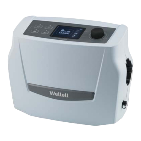
① CPR
② Pump unit
③ Mattress system
④ Quick connector
2.2. Pump Unit
Front
① Quick connector
② Front panel
Rear
① Power switch
② Air filter
③ Fuses
④ Mounting brackets

Optima Turn/English 5
2.3. Front Panel
(1). Power Key
Power Key is to turn on and turn off pump.
(2). Pause Key
Allow caregivers to temporarily stop the action when emergency occurred. Caregivers could
change to other settings during this period of time which will return to the previous mode
automatically after 10 min.
To go to the previous mode setting please press the pause key again.
( ). Panel Lock Key
User interface will be locked automatically 5 minutes after last operation or by pressing Panel
Lock key. To unlock interface, press and hold Panel Lock key for 1 second.
NOTE: Alway unlock u er interface before turning off the pump.
(4). Max Firm Key
The surface will go into Max firm automatically when the power is started.
NOTE: The LED light of Max Firm mode will be on con tantly until the
mattre i reached to the maximum pre ure etting.
NOTE: Thi key i to make ure mattre can be reached maximal
operating pre ure. Thi mode will la t for 20 minute and then return to
previou etting automatically. Thi function can be u ed during patient
tran fer or nur ing procedure for better upport. To di able thi
function, plea e pre Max firm key again.

Optima Turn/English 6
(5). Modes
A. Alternate Mode
The air cells inside the mattress are deflated and inflated periodically to avoid
prolonged pressure in certain areas of patient.
B. Continuou Low Pre ure
Function LED indicator is steady-on in constantly non-alternating mode. The system
will redistribute body mass over a greater surface area at a constant low pressure.
C. Seat Inflation
Press the key to enter the desired mode in alternate or CLP mode for additional
supports to the patient during upright position without bottoming out.
(6). Turning Mode
Three turning modes including LEFT TURN, RIGHT TUTN and
LEFT-SUPINE-RIGHT TURN can be selected. Turning angle is from patients’ direction and
hold at that position for dwell time. Top air cells are non-alternating during the turning process,
and will change to alternating mode when it reaches the position of the desired angle and
when it comes back to supine position as well.
NOTE: When dwell time of 10 min i elected, even reache the po ition
of the de ired angle it doe n't change to alternating mode.
(7). Turning Angle (Up to 0 degree turning under Full-turn Mode, subject 75Kg with
shoulder width 45.7cm)
Light-turn, Half-turn, Full-turn
For One-Time Turning which indicated with LED flashing, press and hold key for
seconds. When turning is completed, it will go back to supine position with alternating
mode.
(8). Pressure Adjust Levels
Press the / to get the correct setting of the pressure level based on patient
weight.
The mattress pressure can be manually adjusted for patient comfort using the key
for a firmer setting and decrease for a softer setting.
NOTE: When the power i tarted (i.e., the urface i inflated), it will
automatically go to "Max Firm" mode to ha ten inflation. Once the
y tem i ready, the y tem will enter CLP mode for 10 minute . If there
are no change of mode , y tem will witch to Alternate Mode.
NOTE: You can al o check if the pre ure i uitable for the patient by
liding one hand beneath the air cell at the level of the patient'
buttock . Alway leave at lea t 1” inch pace between patient and the
tatic cell to prevent bottoming out.

Optima Turn/English 7
(9). Cycle Time
By pressing this button after changing the operation mode, Alternate Mode Cycle
Time can be selected between 10, 15, 20 and 25 minutes.
By pressing this button after changing to the turning mode, Turning Dwell Time can be
selected between 10, 20, 0 and 60 minutes.
NOTE: Cycle time and dwell time duration can be elected ba ed upon
patient comfort and de ired outcome.
(10). Alarm Mute Key
When there is an alarmed situation happened, the number display will show corresponding
error code with buzzer sounded every few seconds. The buzzer can be temporarily
suspended by pressing the Alarm Mute Key. Alarm buzzer will signal repeatedly every
minutes until the alarmed issue is solved.
A. PFA (Power Failure Alarm)
The LED light and buzzer will activate when the power failure happens. To
disable both buzzer and LED, press the mute button.
NOTE: The pump can eal the air in ide the mattre , which temporaily
keep the patient from bottoming out during power failure. Patient
hould be moved if the power failure i ue cannot be olved oon.
B. Low Pre ure Indicator
When low pressure LED lights up, the pressure inside the air mattress is below
normal range. Please refer to troubleshooting guide.
NOTE: The pump can eal the air in ide the mattre , which temporaily
keep the patient from bottoming out during low pre ure condition.
Patient hould be moved if the power failure i ue cannot be olved
oon.
C. Tech. Support
The Service indicator light will activate when an issue occurs related to the
system. Please contact the local representative or place of purchase for
technical support.

Optima Turn/English 8
. Installation
3.1. Pump & Mattre In tallation
NOTE: Unpack the box. Plea e contact your upport per onnel or
package vendor if there are any damage occurred during hipment.
NOTE: USB function i provided for u e by di tributor or authorized
technician .
(1)
(2)
( )
(4)
(5)
(6)
(1). Place the mattress on top of bed frame and foot print toward foot end. Secure the
mattress firmly by fixing the straps to bed frame to ensure mattress will be free from
move. Securing straps is located on base of the mattress
NOTE: Make ure that ALL the Heel Relief Connector and emergency
CPR knob are clo ed and locked in po ition.
NOTE: Make ure the bed ide rail are rai ed.
(2). Hang the pump onto bed rail (foot-end), and adjust hangers to best upright position of the
pump, or place the pump on flat surface.
( ). Connect air hose connectors of air mattress to pump unit. When a "click" sound is felt or
heard, the connection is completed and secured.
NOTE: Check and en ure the air ho e are not kinked or tucked under
mattre .
(4). Plug the power cord into electrical outlet.
NOTE: Make ure the pump unit i uitable for the local power voltage.
NOTE: The plug i al o erved to di connect the device.

Optima Turn/English 9
(5). Then turn on power switch to ON position.
CAUTION: The pump can only be applied to the mattre recommended
by the manufacturer. Do not u e it for any other purpo e. (Applied part:
air mattre ) Do not po ition the equipment o that it i difficult to
operate the di connecting device.
(6). The cable management tape is provided along the side of the mattress to manage power
cable. Please make sure the wire has no signs of damage. After installation, extra length
of the power cord, if any, should be neatly managed to prevent stumble accident and
should be clear of moving bed mechanisms or other possible entrapment area.
NOTE: The EQUIPMENT hould be firmly placed at po ition where
caregiver can acce ea ily.
4. Operation
NOTE: Alway read the operating in truction before u e.
4.1. General Operation
(1). Switch the power on, the mattress starts the initial inflation. The Maxfirm light flashes until
the mattress is fully inflated which takes approximately 0 min.
(2). When the inflation is completed, the system will enter CLP mode for 10 minutes. If there
are no changes of modes, system will switch to Alternate Mode.
( ). Use the Pressure Adjustment key to get the correct setting of therapeutic pressure level
based on patient weight.
NOTE: Pre ure level with the weight guide on the panel i only an
indication and clinical judgement hould alway be taken into
con ideration.
(4). For lateral turning, choose the Left-SUPINE-RIGHT turn key to get standard turning which
helps the patient to turn to both sides and back to supine position, or either one direction
in Left turn or Right turn mode.
NOTE: Do the hand check to check out if the pre ure reduction i
adequate and the patient ha not bottomed out.
NOTE: For patient comfort, alway u e the head pillow when patient i
under turning mode.
4.2. Emergency CPR Operation
NOTE: When there i a need to perform CPR
on the patient, quickly turn the CPR knob to
relea e air from mattre . CPR knob i
located at the right-head ide of the mattre .
The quick connector on the pump unit can be
di connected for even fa ter deflation.

Optima Turn/English 10
4.3. Heel Relief Function
The last five cells from the foot-end have heel-relief connectors. Carers can easily disconnect
the connector and heels can be suspended in air to completely eliminate pressure exerted on
the heels.
For permanent off-loading/pressure relief:
•Select no more than two cells directly under the
area that desired to relieve.
NOTE: Thi one to two cell can be left
permanently deflated.
NOTE: Deflating more than two adjacent cell
may affect the upport of the patient during the
normal alternating cycle.
4.4. Tran portation
NOTE: When there i a need of patient
tran portation, pump with the power cord can
be di connected from the mattre during
tran port. For optimum comfort, change the
y tem to CLP Mode and wait for 5 minute
before di connecting i recommended. Cap on
the quick connector a hown on the left to
keep the air in ide the mattre . The mattre
remain inflated at lea t 24 hour depending
on the etting.

Optima Turn/English 11
5. Cleaning
It is important to follow the cleaning procedures to avoid cross contamination. Be sure to clean
the surface in a dry and dust free environment. Wipe down the pump unit with a damp cloth
pre-soaked with a mild detergent. Avoid contact with dust and proximity to dusty areas. Make
sure that any cleaning agents you use will not harm or corrode the plastic casing on the pump
unit. If your doctor or medical facilities have other special cleaning instruction, please follow the
professional instruction.
CAUTION: Do not immer e or oak pump unit.
WARNING: Do not remove the ca ing of the pump to avoid electrical
hock. All di a embly or repair hould be done by authorized
technician .
CAUTION: The pump doe not need oil lubrication; plea e do not
di emble the y tem.
Cover Material: Stretch
Silver+ Stretch
Wipe down the mattress with 70 % alcohol solution or chlorine solution concentration must be
less than or equal to 1,000 ppm. After disinfecting the mattress, use water and a soft cloth to
wipe off all traces of disinfectant and make sure the mattress is dry before storage. Also the
mattress top cover can be completely removed for laundry with water temperature indicated on
the laundry label; however, it is recommended that user should check with local policy or
regulation to determine the time/temperature ratio required achieving thermal disinfection. The
cover may also be cleaned using sodium hypochlorite diluted in water. After cleaning, please
avoid dust and proximity to dusty areas and all parts should be air dried thoroughly before use.
CAUTION: Do not u e phenolic ba ed product for cleaning.
CAUTION: After cleaning, dry the mattre without direct expo ure of
unlight.
CAUTION: Do not u e ozone or UV di infection a the e method can
damage the urface coating.
6. Storage
(1). To store the mattress, lay the mattress out flat and upsides down.
(2). Roll from the head end towards the foot end with CPR valve open.
( ). Foot-end strap can then be stretched around the rolled mattress to prevent unrolling.
NOTE: Do not kink, crea e or tack the mattre e and do not tore the
y tem in direct unlight, high temperature or moi ture area.

Optima Turn/English 12
7. Maintenance
7.1. General
(1). Check main power cord and plug if there is abrasions or excessive wear.
(2). Check mattress cover for signs of wear or damage. Ensure mattress cover and tubes are
stubbed together correctly.
( ). Check airflow from the opening of the tubes in the quick connector. The airflow should
alternately blow every half of the cycle time between two tubes at the lower right corner
and one of the the other two tubes at the lower left corner will blow to give desired turning
angle when it is under turning mode.
(4). Check the air hoses if there is kink or break. For replacement, please contact local
representative or place of purchase.
7.2. Fu e Replacement
(1). Disconnect the plug from mains power when a
blown fuse is suspected.
(2). Remove the cover of the fuse holder by means
of a flat screwdriver.
( ). Insert a new fuse of the correct rating in, and
replace the cover of the fuse holder back. The
fuse should be rated as T1AL/250V type and
VDE approved.
7.3. Air Filter Replacement
(1). Open the air filter cap located at the back of pump.
(2). Replace with a clean filter and put the cover lid back.
The filter is reusable and can be washed gently with
a mild detergent and water. Dry the filter before use.
( ). Suggested to check and replace air filter regularly
every six month.
8. Expected Service Life
The products are intended to offer safe and reliable operation when use or installed according
to the instructions provided by Apex Medical. Apex Medical recommends that the system be
inspected and serviced by authorized technicians if there are any signs of wear or concerns
with device function and indication on products. Otherwise, service and inspection of the
devices generally should not be required.

Optima Turn/English 1
9. Trouble Shooting
Q1 Power i not ON
‧ Check if the plug is connected to mains.
‧ Check for a blown fuse.
Q2 Low Pre ure Alarm i on
‧ Check if the Quick Connector is tightly secured.
‧ Check if all tubing connections along mattress are secured.
‧ Check if the air hoses are kinked or broken.
‧ Check if the CPR knob is tightly closed.
Q3 Power Failure Alarm i on
‧ Check if the power is suddenly shut down.
‧ Check if the power cord is connected properly.
Q4 Patient i bottoming out
‧ Pressure setting might be inadequate for the patient, increase comfort range 1 level higher
and wait for a few minutes for best comfort.
Q5 Mattre form i loo e
‧ Check if all the snap buttons or straps of mattress are all securely fastened.
‧ Check if the mattress is fixed to the bed frame by straps.
Q6 No air relea ed from ome air outlet of the air tube connector
‧ This is in alternating mode. The air is released through outlets by turns at each cycle.
If the problems you have are not solved by the above information, please contact local
representative or place of purchase.
10. Error Code Table
Code No. De cription
00 Initial inflation overtime
01-06 Low pressure
08-12 System malfunction
16 Pressure control system malfunction
17 System access control malfunction
18 Mattress disconnected
19 Connect to the wrong mattress

Optima Turn/English 14
11. Technical Specifications
Item Specification
Pump
Power Supply (Note: See
rating label on the product) AC 2 0V 50 Hz, 0.25A (for 2 0V system)
Fuse Rating T1AL, 250V
Cycle time (Alternating) 10, 15, 20, 25 min.
Dwell time (Turning) 10, 20, 0, 60 min.
Dimension (L x W x H) 4.1 x 16.5 x 26.0 cm
Weight 4.5 Kg / 9.9 lb
Environment
Atmospheric
Pressure 700 hPa to 1060 hPa
Temperature
Operation: 10°C to 40°C (50°F to 104°F)
Storage: -15°C to 50°C (5°F to 122°F)
Shipping: -15°C to 70°C (5°F to 158°F)
Humidity 10% to 90% non-condensing
Classification
Class II , Type BF, IP21
Applied Part: Air Mattress
Not suitable for use in the presence of a flammable
anesthetic mixture (No AP or APG protection)
Mattre
Model 5” cells & 10” side bolster
Dimension (L x W x H) 200x85/90x1 cm
78.7”x .5/ 5.4”x5”
Weight 12.5 Kg / 27.5 lb
Max. Support Weight 180 Kg / 97 lb
NOTE:
Con ult the di tributor or EU repre entative for further technical
document .
The pecification i al o uitable for other area operating with ame
power upply.
The manufacturer re erve the right to modify the pecification
without notice.

Optima Turn/English 15
Appendix A: EMC Information
Guidance and Manufacturer’ Declaration- Electromagnetic
Emi ion :
This device is intended for use in the electromagnetic environment specified below. The user of
this device should make sure it is used in such an environment.
Emissions Test Compliance Electromagnetic Environment-Guidance
RF emissions
CISPR 11
Group1
The device uses RF energy only for its internal function.
Therefore, its RF emissions are very low and are not
likely to cause any
interference in nearby electronic
equipment
RF emissions
CISPR 11
Class B
The device is suitable for use in all establishments,
including domestic establishments and those directly
connected to the public low-
voltage power supply
network
Harmonic emissions
IEC61000- -2 Class A
Voltage fluctuations /
Flicker emissions
IEC61000- -
Complies
Warning:
1.
The device should not be used adjacent to or stacked with other equipment. If adjacent or
stacked use is necessary, the device should be
observed to verify normal operation in the
configuration in which it will be used.
2. Use of accessories, transducers and cables other than those specified or provided by
the manufacturer of this equipment could result in increased electromagnetic emissions
or decreased electromagnetic immunity of this equipment and result in improper
operation.
. Portable RF communications equipment (including peripherals such as antenna cables
and external antennas) should be used no closer than 0 cm (12 inches) to any part
of the
Pump, including cables specified by the manufacturer. Otherwise, degradation of the
performance of this equipment could result.

Optima Turn/English 16
Guidance and Manufacturer’ Declaration- Electromagnetic Immunity:
This device is intended for use in the electromagnetic environment specified below. The user of
this device should make sure it is used in such an environment.
Basic EMC
standard
Immunity Test Levels
Compliance
Levels
Electromagnetic
Environment-Guidance
Professional
healthcare
facility
environment
HOME
HEALTHCARE
ENVIRONMENT
Electrostatic
Discharge (ESD)
IEC61000-4-2
±8 kV contact
± 2, 4, 8, 15 kV air
±8 kV
contact
± 2, 4, 8, 15
kV air
Floors should be wood,
concrete or ceramic tile.
If floors are covered
with synthetic material,
the relative humidity
should be at least 0 %.
Electrical fast
transient/ burst
IEC61000-4-4
±2 kV, 100 kHz for power supply line
±1 kV, 100 kHz for input/output line
±2 kV, 100
kHz for
power
supply line
Mains power quality
should be that of
atypical commercial or
hospital environment
Surge
IEC61000-4-5
± 0.5, 1 kV (line to line)
± 0.5, 1, 2 kV (line to earth)
± 0.5, 1 kV
(line to line)
Mains power quality
should be that of
atypical commercial or
hospital environment.
Voltage dips,
short
interruptions and
voltage variations
on power supply
input lines
IEC61000-4-11
Voltage Dips:
i) 100% reduction for 0.5 period,
ii) 100% reduction for 1 period,
iii) 0% reduction for 25/ 0 period,
Voltage Interruptions:
100% reduction for 250/ 00 period
2 0 Vac
Mains power quality
should be that of a
typical commercial or
hospital environment. If
the user of this device
requires continued
operation during power
mains interruptions, it is
recommended that the
device be powered from
an uninterruptible power
supply or a battery.
Power frequency
(50/60Hz)
magnetic field
IEC61000-4-8
0 A/m 0 A/m 0 A/m
Power frequency
magnetic fields should
be at levels
characteristic of a
typical location in a
typical commercial or
hospital environment.
Conducted RF
IEC 61000-4-6
Vrms
0,15 MHz –
80
MHz
6 Vrms in ISM
bands
between 0,15 MHz
Vrms
0,15 MHz –
80
MHz
6 Vrms in ISM
and amateur
radio bands
Vrms
0,15 MHz –
80 MHz
6 Vrms in
ISM and
amateur
Portable and mobile RF
communications
equipment should be
used no closer to any
part of this device,
including cables, than

Optima Turn/English 17
and 80 MHz
80 % AM at 1 kHz
between
0,15 MHz and 80
MHz
80 % AM at 1
kHz
radio bands
between
0,15 MHz
and 80 MHz
80 % AM at
1 kHz
there commended
separation distance
calculated from the
equation applicable to
the frequency of the
transmitter.
Recommended
separation distance
d=√ 150kHz to
80MHz
d=0.6√ 80MHz to
800MHz
d=1.2√ 800 MHz to
2.7GHz
Where P is the
maximum output power
rating of the transmitter
in watts (W) according
to the transmitter
manufacturer and d is
the recommended
separation distance in
meters (m).b
Field strengths from
fixed RF transmitters, as
determined by an
electromagnetic site
survey ,a should be
less than the
compliance level in
each frequency ranged.
Interference may occur
in the vicinity of
equipment marked with
the following symbol:
Radiated RF EM
Fields
IEC61000-4-
V/m
80 MHz - 2.7 GHz
80 % AM at 1 kHz
80 - 5800 MHz,
9-28 V/m,
Pulse modulation
or FM ±5 kHz
deviation , (1kHz
sine)
10 V/m
80 MHz -
2.7
GHz
80 % AM at 1
kHz
80 -
5800 MHz,
9-28 V/m,
Pulse
modulation or
FM ±5 kHz
deviation, (1kHz
sine)
10 V/m
80 MHz -
2.7 GHz
80 % AM at
1 kHz
80 -
5800
MHz,
9-28 V/m,
Pulse
modulation
or FM ±5
kHz
deviation,
(1kHz sine)
NOTE 1: UT is the a.c. mains voltage prior to the application of the test level
NOTE 2: At 80 MHz and 800 MHz, the higher frequency range applies.
NOTE : These guidelines may not apply in all situations. Electromagnetic propagation is
affected by absorption and reflection from structures, objects and people
Table of contents
Languages:
Other Wellell Medical Equipment manuals
Popular Medical Equipment manuals by other brands

Your Body, Your Time
Your Body, Your Time GT-OVU04 instruction manual

natus
natus XLTEK EMU128 User and service manual

Prism Medical UK
Prism Medical UK A320B owner's manual

Atos Medical
Atos Medical CareTips Provox LaryButton How to use

NRS Healthcare
NRS Healthcare N94561 User instructions

SciCan
SciCan SANAO Red Dot Quick reference guide

Cardinal Health
Cardinal Health CATALYST Patient Quick Reference Guide

natus
natus Nicolet user guide

LINET
LINET Sprint 100 User manual and technical description

STARmed
STARmed VIVA combo RF Generator user guide

Chattanooga Group
Chattanooga Group Vectra Genisys 2758 user manual

Henry Schein
Henry Schein MD300K2 Instructions for use