7
This apparatus complies with the IEC 60601-1-2 international standard. The requirements of this internati-
onal standard are: CISPR11, GROP1, and CLASS B.
1.6 Explanation of Symbols
1.7 Product Features
• Compact, light in weight and simple to use.
• TFT displaying screen with adjustable backlight.
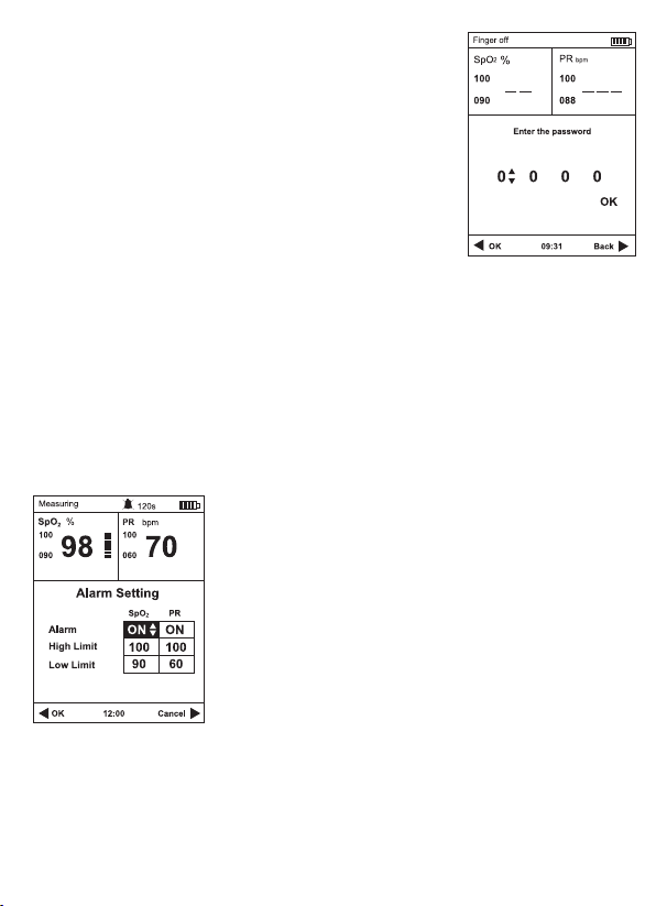
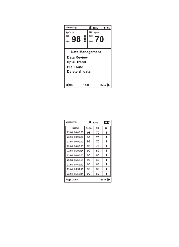
• Up to 127 user ID and 72-hour records storage.
• Visual and three-level audible alarms, low battery alarm.
• Data transfer to PC by USB cable.
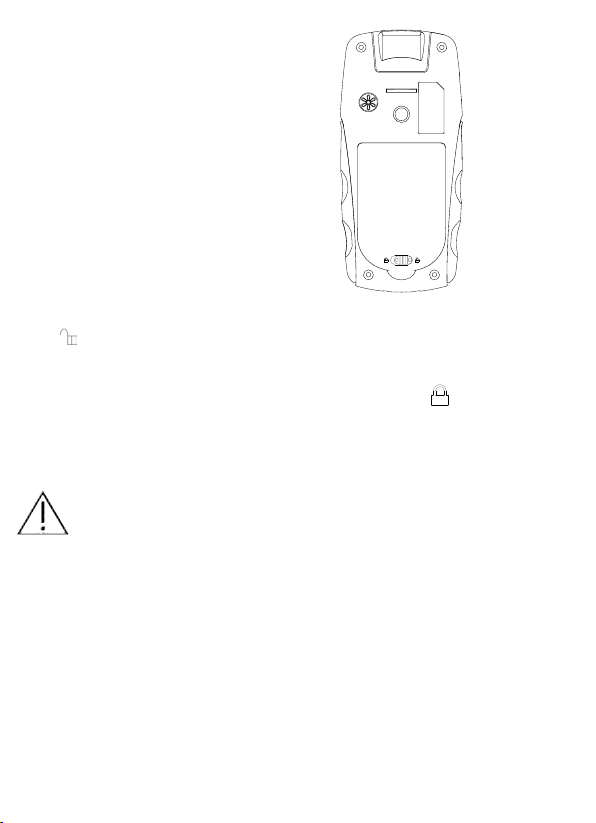
• Powered by three AA alkaline batteries or power adapter (optional).
1.8 Contraindication
None
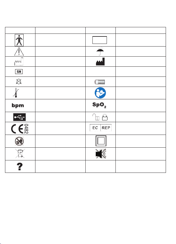
Symbol Explanation Symbol Explanation
Type BF applied part Protected against dripping
water
Caution Prevent from rain
Date of Manufacture Manufacturer’s information
Serial number User ID
Audio alarm inhibition Battery power indication
Storage temperature and
relative humidity
Follow instructions for use
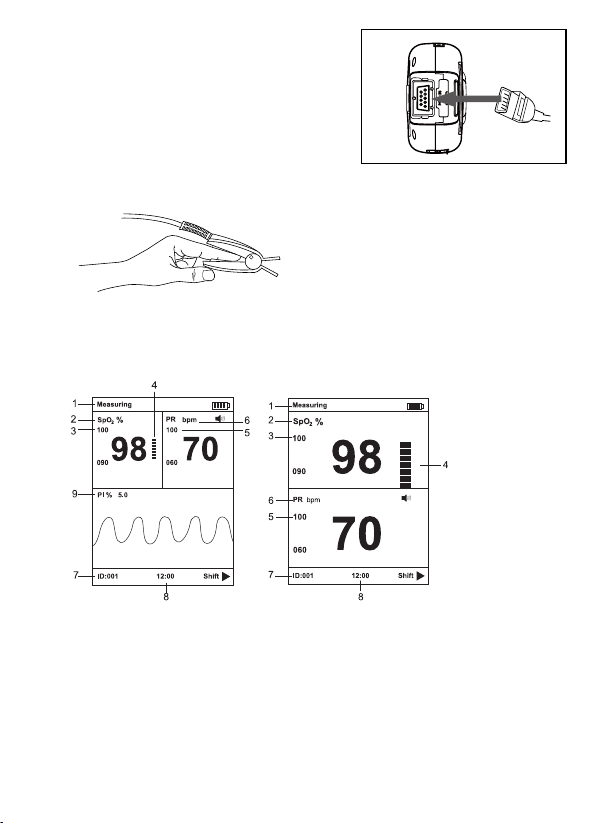
Pulse rate Hemoglobin Oxygen
Saturation
USB cable is connected Battery cover unlock / lock
European union approval Authorized representative in
the European community
Do not discard the device
and other components
Class II equipment
Waste electrical and
electronic equipment
Beep silence
Indicate the signal is not
stable
IPX1
-20°C
70°C
RH≤93%
non-condensing
ID
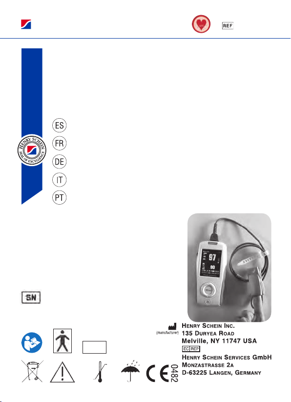
PULSE OXIMETER
MD300K2
- 4 -
t h i s i n t e r n a t i o n a l s t a n d a r d a r e : C I S P R 11, G R O P 1, and C L A S S B .
1.6 Explanation of Symbols
Symbol Explanation Symbol Explanation
T y p e B F a p p l i e d p a r t IPX1 P r o t e c t e d a g a i n s t d r i p p i n g w a t e r
C a u t i o n Pr e v e n t f r o m r a i n
D a t e o f Ma n u f a c t u r e Ma n u f a c t u r e r ’ s i n f o r m a t i o n
SN Se r i a l n u m b e r Us e r I D
Au d i o a l a r m i n h i b i t i o n B a t t e r y p o w e r i n d i c a t i o n
S t o r a g e t e m p e r a t u r e a n d
r e l a t i v e h u m i d i t y Fo l l o w i n s t r u c t i o n s f o r u s e
bpm P u l s e r a t e SpO2H em oglobin O x y gen S a t u r a t i o n
US B c able i s c o n n e c t e d B a t t e r y c o v e r u n l o ck / l o ck
European union approval A u t h o r i z e d r e p r e s e n t a t i v e i n t h e
Eu r o p e a n c o m m u n i t y
D o n o t d i s c a r d t h e d e vi c e
and o t hercom ponents C l a s s I I equipm ent
W a s t e e l e c t r i c a l a n d
e l e c t r o n i c e q u i p m e n t Beep s i l e n c e
Al a r m i n h i b i t ?In d i c a t e t h e s i g n a l i s n o t s t a b l e
1.7 Product Features
•C o m p a c t , lig h t i n w e i g h t a n d s i m p l e t o u s e .
•T F T d i s p l a y i n g s c r e e n w i t h a d j u s t a b l e b a c k l i g h t .
•Up t o 127 u s e r I D a n d 72- h o u r r e c o r d s st orage.
•V i s u a l a n d t h r e e - l e v e l a u d i b l e a l a r m s, l o w b a t t e r y a l a r m .
•D a t a t r a n s f e r t o P C b y US B c a b l e .
•P o w e r e d b y t h r e e A A a l k a l i n e b a t t e r i e s o r pow eradapter(optional).
1.8 Contraindication
None
PULSE OXIMETER
MD300K2
- 4 -
t h i s i n t e r n a t i o n a l s t a n d a r d a r e : C I S P R 11, G R O P 1, and C L A S S B .
1.6 Explanation of Symbols
Symbol Explanation Symbol Explanation
T y p e B F a p p l i e d p a r t IPX1 P r o t e c t e d a g a i n s t d r i p p i n g w a t e r
C a u t i o n Pr e v e n t f r o m r a i n
D a t e o f Ma n u f a c t u r e Ma n u f a c t u r e r ’ s i n f o r m a t i o n
SN Se r i a l n u m b e r Us e r I D
Au d i o a l a r m i n h i b i t i o n B a t t e r y p o w e r i n d i c a t i o n
S t o r a g e t e m p e r a t u r e a n d
r e l a t i v e h u m i d i t y Fo l l o w i n s t r u c t i o n s f o r u s e
bpm P u l s e r a t e SpO2H e m o g l o b i n O x y g e n S a t u r a t i o n
US B c able i s c o n n e c t e d B a t t e r y c o v e r u n l o ck / l o c k
European union approval A u t h o r i z e d r e p r e s e n t a t i v e i n t h e
Eu r o p e a n c o m m u n i t y
D o n o t d i s c a r d t h e d e v i c e
and o t hercom ponents C l a s s I I equipm ent
W a s t e e l e c t r i c a l a n d
e l e c t r o n i c e q u i p m e n t Beep s i l e n c e
Al a r m i n h i b i t ?Indi c a t e t h e s i g n a l i s n o t s t a b l e
1.7 Product Features
•C o m p a c t , lig h t i n w e i g h t a n d s i m p l e t o u s e .
•T F T d i s p l a y i n g s c r e e n w i t h a d j u s t a b l e b a c k l i g h t .
•Up t o 127 u s e r I D a n d 72- h o u r r e c o r d s s t o r a g e .
•V i s u a l a n d t h r e e - l e v e l a u d i b l e a l a r m s, l o w b a t t e r y a l a r m .
•D a t a t r a n s f e r t o P C b y US B c a b l e .
•P o w e r e d b y t h r e e A A a l k a l i n e b a t t e r i e s o r pow eradapter(optional).
1.8 Contraindication
None