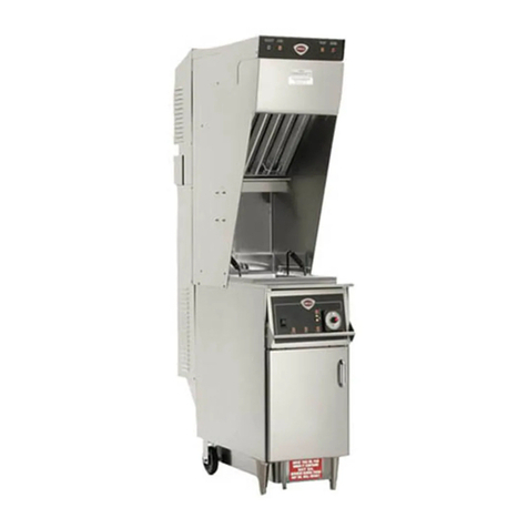
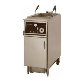
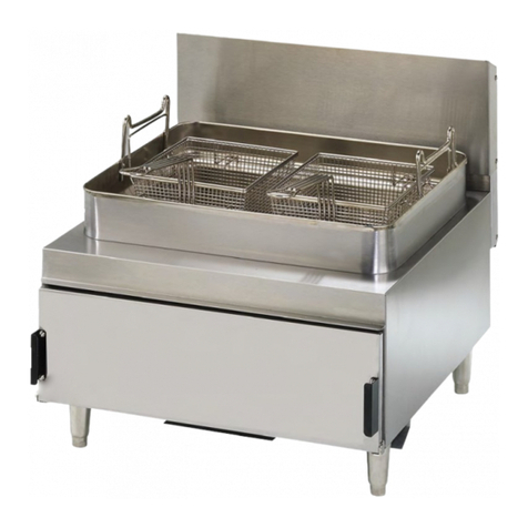
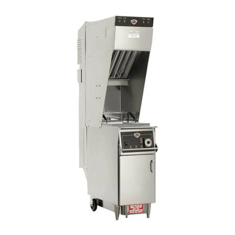
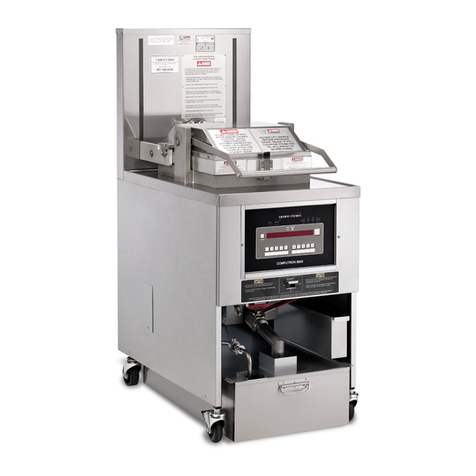
Wells WFGA-60FS User manual

OPERATION
MANUAL
for
GAS FRYER
model
WFGA-60FS
includes:
Installation
Use and Care
IMPORTANT: DO NOT DISCARD THIS MANUAL
This manual is considered to be part of the FRYER and is to be given to the OWNER or
MANAGER of the restaurant, or to the person responsible for TRAINING OPERATORS
of the FRYER. Additional manuals are available from your WELLS DEALER .
THIS MANUAL MUST BE READ AND UNDERSTOOD BY ALL PERSONS USING OR
INSTALLING THIS FRYER. Contact your WELLS DEALER if you have any questions
concerning installation, operation or maintenance of this equipment.
Part. No 301098 Rev. A M371 012100 cps
WELLS MANUFACTURING COMPANY
2 ERIK CIRCLE, P. O. Box 280
Verdi, NV 89439
Customer Service (775) 345-0444 Ext.502
fax: (775) 345-0569
www.wellsbloomfield.com
371

Allcommercialcookingequipmentmanufacturedby
WELLS MFG. CO. is warranted against defects in
materials and workmanship for a period of one year
from the date of original installation or 18 months
from the date of shipment from our factory, which-
ever comes first, and is forthe benefit of the origi-
nal purchaser only.
THISWARRANTYISTHECOMPLETEAND ONLY
WARRANTY, EXPRESSED OR IMPLIED IN LAW
OR IN FACT, INCLUDING BUT NOT LIMITED TO,
WARRANTIES OF MERCHANTABILITY OR FIT-
NESS FOR ANY PARTICULAR PURPOSE, AND/
OR FOR DIRECT, INDIRECT OR CONSEQUEN-
TIAL DAMAGES IN CONNECTION WITH WELLS
MFG. CO. PRODUCTS. This warranty is void if it is
determined that, upon inspection by an authorized
service agency, the equipment has been modified,
misused, misapplied, improperly installed, or dam-
aged in transit or by fire, flood or act of God. It also
does not apply if the serial nameplate has been re-
moved, or if service is performed by unauthorized
personnel.
The prices charged by Wells Mfg. Co.for its prod-
ucts are based upon the limitations in this warranty.
Seller’s obligation under this warranty is limited to
the repair of defects without charge by a Wells Mfg.
Co. factory authorized service agency or one of its
sub-service agencies. This service will be provided
on customer’s premises for non-portable models.
Portablemodels(adevicewitha cordand plug)must
be taken or shipped to the closest authorized ser-
viceagency,transportation charges prepaid, for ser-
vice. Inaddition to restrictions containedinthis war-
ranty, specific limitations are shown in the Service
Policy and Procedure Guide. Wells Mfg. Co. autho-
rizedservice agencies are located in principal cities.
This warranty is valid in the United States and
Canada and void elsewhere. Please consult your
classifiedtelephonedirectory,yourfoodserviceequip-
mentdealer orwritethe Factory ServiceDepartment,
Wells Manufacturing Company, P.O.Box280, Verdi,
Nevada 89439, phone (775) 345-0444 or (888) 492-
2782, for information and other details concerning
warranty.
LIMITED WARRANTY STATEMENT
SERVICE POLICY AND PROCEDURE GUIDE
ADDITIONAL WARRANTY EXCLUSIONS
1. Resetting of safety thermostats, circuit breakers, overload protectors, over temperature protectors and/or fuse replacements are not
covered by this warranty unless warranted conditions are the cause.
2. All problems due to operation involvingfuel type, gas pressure, voltages or phase other than specified on equipment nameplates
are not covered by this warranty.
Conversion to correct fuel type and pressure adjustment, correct voltage and/or phase must be the customers responsibility.
3. All problems due toelectrical connections not made in accordance with electrical code requirements and wiring diagrams
supplied with the equipment are not covered by this warranty.
4. Replacement of itemssubject to normal wear, to include such items as knobs, light bulbs; and, normal maintenance functions including
adjustments of thermostats, adjustment of micro switches and replacement of fuses and indicating lights are not covered by warranty.
5. Servicing of filters must be the customer’s responsibility and all problems associated with clogged filters are not covered by this waranty.
6. Set-up, adjustment, calibration, repair and servicing ofthird party equipment and systems, such asfire suppression systems, are not
covered by this warranty, and must be the customer’s responsibility.
7. Full use, care, and maintenance instructions are supplied with each machine. Noted maintenance and preventative maintenance items,
such as servicing and cleaning schedules, are customer responsibility. Those miscellaneous adjustments noted are customer
responsibility. Proper attention to preventatve maintenance and scheduled maintenance procedures will prolong the life of the machine.
8. Travel mileage is limited to sixty (60) miles from an Authorized Service Agency or one of its sub-service agencies.
9. All labor shall be performed during regular working hours. Overtime premium will be charged to the buyer.
10. All genuine Wells replacement parts are warranted for ninety (90) days from date of purchase on non-warranty equipment. This parts
warranty is limited only to replacement of the defective part(s). Any use of non-genuine Wells parts completely voids any warranty.
11. Installation, labor, and job check-outs are not considered warranty and are thus not covered by this warranty.
12. Charges incurred by delays, waiting time or operating restrictions that hinder the service technician’s ability to perform service are not
covered by warranty. This includes institutional and correctional facilities.
SHIPPING DAMAGE CLAIM PROCEDURE
NOTE: For your protection, please note that equipment in this shipment was carefully inspected and packaged by skilled personnel before
leaving the factory. Upon acceptance of this shipment, the transportation company assumes full responsibility for its safe delivery.
IF SHIPMENT ARRIVES DAMAGED:
1. VISIBLE LOSS OR DAMAGE: Be certain that any visible loss or damage is noted on the freight bill or express receipt, and that
the note of loss or damage is signed by the delivery person.
2. FILE CLAIM FOR DAMAGE IMMEDIATELY: Regardless of the extent of the damage.
3. CONCEALED LOSS OR DAMAGE: if damage is unnoticed until the merchandise is unpacked, notify the transportation company
or carrier immediately, and file “CONCEALED DAMAGE” claim with them. This should be done within fifteen(15) days from the
date the delivery was made to you. Be sure to retain the container for inspection.
Wells Manufacturing cannot assume liability for damage or loss incurred in transit. We will, however, at your request, supply you with the
necessary documents to support your claim.
TABLE OF CONTENTS
GENERAL SPECIFICATIONS
1
DIMENSIONS
Wide 18.19”
Deep 38.25”
High 47.44”
CAPACITIES Lb. Kg.
CookingOil (LiquidShortening Only) 60 27
Chicken(fresh) (FullSize Basket) 30 13
Chicken(frozen) (FullSize Basket) 25 11
ELECTRICAL
VoltageRequirement 120 VAC / 5A
1Ø operationONLY
GAS
NaturalGas(3.5”water pressure) 62,000 BTU/hr
* FieldconvertibletoLP/Propane(10” waterpressure)
* TO BE PERFORMED BY QUALIFIED TECHNICIAN ONLY
Warranty InsideCover
Specifications 1
FeaturesandOperatingControls 2
SafetyProcedures 4
InstallationInstructions 5
OperatingInstructions-SolidState Controller 10
* MaintenanceInstruction
CradleLiftAssemblyLubrication 14
CradleRollerAssembly 15
FilterLeaf Assembly 15
FilteringOil 17
DiscardingUsedOil 19
CleaningtheFryer 21
* Troubleshooting 23
ServicePartsList 26
* TO BE PERFORMED BY QUALIFIED PERSONEL ONLY

2
1. POWER SWITCH FRYER position turns ON the FRYER and energizes the UPPER
(FRYER-OFF-FILTER)CONTROL PANEL; and, turns OFF the FILTER PUMP.
Burner circuits are energized and regulate to the programmed
temperature.
OFF position turns OFF the FRYER .
FILTER position energizes the FILTER PUMP.
2. TIME KEY Used to check and set menu times.
3. TEMP KEY Used to check and set menu temperatures.
4. READOUT LED display of various data and functions.
5. UP ARROW KEY Used to raise FRY BASKET and raise program settings .
6. DOWN ARROW KEY Used to lower FRY BASKET and lower program settings .
7. MENU KEYS Used to begin a menu time/temp cycle.
Keys 1 thru 6 are programmable for time and temperature;
Key 7 is available for individually set time/temp cook cycles
8. FUNCTION KEYS Used to perform the functions of PAUSE, CLEAN, STANDBY,
BASKET (raise/lower) and FILTER (warning/acknowledge)
9. HI-LIMIT THERMOSTAT Providesover-temperature protectionbyde-energizing the
GAS VALVES if the oil temperature exceeds the factory-set
limit. RESET must be performed manually. Allow the oil to
cool below 350ºF (177ºC), then firmly press the red button on
the LOWER CONTROL PANEL until it “clicks”.
WFGA-60FS w/SOLID STATE CONTROLLER
FEATURES and OPERATING CONTROLS
FRONT VIEW
9
BACK VIEW
LOWER CONTROL PANEL
RESET
HI-LIMIT
UPPER CONTROL PANEL
8
10
3452 6
7
1 2 3 4 5 6 7
TIME TEMP
HEAT READY MANUAL
MANUAL PAUSE CLEAN STANDBY BASKET FILTER
FRYER
OFF
FILTER
1
11
12
13
18
19
14
20
21
15
16
17
22
23

3
10. SONALERT Audible alarm to signal end of a cook cycle and other programmed
functions.
11. LIFT CRADLE Raises and lowers FRY BASKET.
12. FRYBASKET Sits on the LIFT CRADLE and holds product to be cooked.
Raised and lowered by the LIFT CRADLE.
13. OIL FILTER RESERVOIR Holds the filter element. Holds oil during filtering cycle.
14. EXHAUST FLUE Twin flues. Hot flue gases exit here.
15. LIFT MOTOR Raises / lowers LIFT CRADLE. Accessible for lubrication thru
the access plate in back panel.
16. VENTILATION SLOT Provides air inlet for COOLING FAN inside CONTROL PANEL.
NEVER ALLOW WATER TO GET INTO THIS SLOT.
17. FILTER PUMP MOTOR The FILTER PUMP MOTOR is equipped with an over-
RESET BUTTON heating protection device.
RESET must be performed manually. Allow the motor to
cool for approx. 15 min., then firmly press the red button on
the back of the motor until it “clicks”.
18. BURNER ASSEMBLY Two assemblies; comprised of orifice, shutter, burner and ignitor.
19. DRAIN VALVE OVAL Opens and closes the DRAIN VALVE.
HANDLE To OPEN, turn the handle counterclockwise (to vertical).
To CLOSE, turn the handle clockwise (to horizontal).
20. GAS SHUT-OFF VALVES Two valves, one located behind each gas control valve. Allow
isolation of either burner circuit.
21. GAS CONNECTION Gassupply connectshere.
22. POWER CORD 115V 15Amp, NEMA 5-15P
23. DATA PLATE Identifiestheappliance manufacturer,modeland serial number;
alsogiveselectricalratings, gasratings.
CAUTION: FIRE HAZARD / HOT OIL
THE HI-LIMIT THERMOSTAT IS A FIRE PROTECTION DEVICE.
Iftrippingpersists, contactyourauthorized Wellsserviceagency forrepairs.
DO NOTATTEMPT TO BYPASS OR HOLD IN THE BUTTON OF THE
HI-LIMIT THERMOSTAT. AFIRE WILL RESULT.

4
SAFETY PROCEDURES
Knowledgeof properprocedures is essential to the safe operationof gas-firedcooking
equipment. In accordance with generally accepted product safety labeling guidelines for
potential hazards, the following signal words and symbols are used throughout this manual.
DANGER
WARNING -Warning isusedto indicatethe presenceof ahazard whichcan cause
personalinjury andpossiblydeath, ormajorproperty damage,inthe eventthe state-
ment is ignored.
CAUTION - Caution is used to indicate the presence of a hazard which will or can
cause minor personal injury, or property damage in the event the statement is ignored.
NOTE-Noteisusedto notifypersonnelofinstallation, operationormaintenanceinformation
which is important, but not hazard related.
DANGER - Danger is used to indicate the presence of a hazard which will
cause severe personal injury, death, or substantial property damage in the
event the statement is ignored.
FRYER PRECAUTIONS AND GENERAL INFORMATION
1. This fryer is intended for use to deep fry food products for human consumption. No other use
is recommended or authorized by the manufacturer or its agents.
2. This fryer is intended foruse in commercial establishments, where all operators are familiar with
the appliance use, limitations and associated hazards. OPERATING INSTRUCTIONSAND
WARNINGS MUST BE READ AND UNDERSTOOD BY ALL OPERATORS AND USERS.
3. Your WELLS fryer is equipped with an oil filtration system, which is designed to filter hot liquid
shortening ONLY. Water, cleaning agents or other liquids will damage the FILTER PUMP.
4. This piece of equipment is made in the USA and has American sizes on hardware.
5. Any trouble shooting guides, component views or parts lists included in this manual are for general
referenceonly, andareintended foruse byqualifiedtechnical personnel.
6. This manual should be considered a permanant part of this appliance. This manual and all
supplied instructions, diagrams, schematics, parts break downs, notices and labels must remain
with the appliance if it is sold or moved to another location.
CAUTION - Used to indicate the presence of an electrical hazard which will or can
cause personal injury, or property damage in the event the statement is ignored.

INSTALLATION INSTRUCTIONS
5
A. UNPACKINGAND INSPECTION
1. Carefully removetheFRYER fromthecarton. Remove allblueprotectiveplasticfilm,
packaging materialsand accessories fromthe FRYER and theFILTERRESERVOIRbefore
connecting electrical power to theFRYERorotherwiseperforminganyinstallationprocedures.
NOTE: DO NOT discard theCARTON and otherPACKAGINGMATERIALuntilyou have
inspected the fryer for hidden damage and tested it forPROPEROPERATION.
Refer to SHIPPING DAMAGE CLAIM PROCEDURE ontheinside front cover ofthismanual.
2. Read all instructions inthismanualcarefully before startinginstallationofthis fryer. READ
AND UNDERSTAND ALL LABELS AND DIAGRAMSATTACHED TO THE FRYER.
3. Carefully account forallcomponents and accessoriesbeforediscarding packingmaterials.
Storetheaccessoriesina convenientplacefor lateruse:
COMPONENTS
1ea. FILTER RESERVOIR
1ea. FILTER LEAF with O-RING
4ea. FILTER RESERVOIR SUCTION TUBE O-RING (on FILTER
RESERVOIR SUCTION TUBE)
1ea. FRY BASKET, FULL SIZE
1ea. LIFTCRADLE
1ea. FRYPOT LID
ACCESSORIES
1ea. LITERATURE PACKAGE
1bx. FILTER POWDER
2ea. HIGH TEMPERATURE BRUSHES
1ea. STAINLESS STEEL SHOVEL
1ea. CLEANOUT DOWEL (WOOD ROD)
1ea. “T”-SHAPED SCRAPER w/ INSTRUCTIONS
B. SERVICE TECHNICIAN INSTALLATION NOTES
1. Installation andstartupshouldbe performedbyanauthorizedinstallation company.
Installer must recordfryer installationparticulars onthe CUSTOMER SERVICEDATAform on
page 27 of this manual.
2. Verify thatthisFRYERinstallation isincompliance withthespecificationslisted inthismanual
and with local code requirements. THIS ISTHERESPONSIBILITY OFTHE INSTALLER.
3. Certain codesrequire fryerstoberestrained witha CABLEor otherRESTRAINTDEVICE.
It is the RESPONSIBILITY OF THE INSTALLER to check with theAUTHORITY HAVING
JURISDICTION,inorder toascertain theapplicabilityofthis requirement toTHIS SPECIFIC
FRYER INSTALLATION.

D. PLUMBING INSTALLATION
1. The installation ofthisfryer mustconformtolocal codes. Intheabsence of localcodes,the
installationofthisfryer must conform withtheNationalFuel Gas Code (ANSIZ223.1).
InCanada,theNationalGas InstallationCode(CAN/CGAB149.2) isapplicable.
2. In anyinstancewheregas supplypressureis inexcess
of 15”waterpressure (1/2 psi or 3.45kP), thefryermust
be isolated from the supply piping byclosing itstwo
individualmanualshut-offvalves(item20).
IMPORTANT:Failuretoisolatethefryerfromexcessive
pressurewill damagethegasvalvesandallow rawgas
toleakintotheroom.
6
C. EQUIPMENT SET-UP
1. AsingleWFGA-60FSgas-fired fryer requiresaminimumof 700 cubicfeetperhour (12 CFM)
make-upair. Theventilation forthekitchen musthavesufficient capacitytoprevent a
negative-pressurecondition. DO NOTobstructorrestrictventilationandmake-upairrequired
tosupportcombustion.
2. SetuptheFRYER only onafirm, levelsurface. Clearancesfromall combustibleandnon-
combustible construction is 1” minimum.Theareaaroundthe fryermustbe keptclearof
combustibles.
3. LEVELING: Verify that the fryer sits firmlyON BOTH CASTERSAND ON BOTH LEGS.
Withaspiritlevel, check that thefryerislevelfront-to-back and side-to-side. With the
adjustablelegs,adjustasrequiredtolevel thefryer.
4. DO NOT obstruct the flowofthetwoexhaustflues (item 14) at thetoprearofthe fryer. It is
especiallycriticalthat gassupplypipingandelectricalsupplycord and/orreceptacleberouted
awayfromthe pathofthe hotcombustionfumes.
5. This fryermustbeinstalledandoperatedunder aventilation hoodconformingtoallapplicable
localcodes. Combustionfumes mustbevented inaccordancewith localcodes.
6. Cooking andcleaningfunctions requireunobstructedaccess. The frypot,controlpaneland
frontaccesspanel mustbemaintained freefromobstructions. Therear accesspanelmust be
accessibleformaintenance.
GAS VALVE
OPEN
CLOSED
DANGER
FIRE AND EXPLOSION HAZARD
GAS CONNECTIONS AND GAS ADJUSTMENTS MUST BE MADE BY
A LICENSED PLUMBER, CERTIFIED IN GAS INSTALLATION
Agasexplosion will cause deathorserious injury.

E. ELECTRICAL INSTALLATION
1. Fryer electricaldiagramandtroubleshootingschematic (item22)arelocatedon theinsideof
thefryerdoor.
2. The fryerisequipped withathree-prong groundingplug(NEMA15-5P)for yourprotection
againstshock hazard. Thefryermustbepluggeddirectlyintoaproperlygroundedthree-prong
receptacle(NEMA15-5R).
3. The installation ofthisfryer mustconformtolocal codes. Intheabsence of localcodes,the
installationofthis fryermustconform withtheNational ElectricalCode(ANSI Z223.1).
InCanada,CSA C22.2is applicable.
4. Because the fryerdrawsless than8amps,two fryersmaybe plugged intothesame 15amp
circuitifrequired.
3. Thisfryeris orificedatthe factory fornaturalgas atapressure of3.5” ofwater column.
Theinstalledorifice issuitableforuse at -280to2999 feet (-85to914 meters)elevation.
Itisthe responsibilityofthe installertoinstall thefactoryrecommended orificeandpressure
regulatorkitsuitableforthefueltypeandelevation atthe finalinstallationsite.
Theredtag(p/n301217)attachedtothegas connectionprovidespressuresettingsandpart
numbersforconversionkits applicable tovariousfuelsand altitudes.
NOTE: Failuretoinstallproperorificescanburncookingoil andcausepotentialburner
andfluesystemfailure.
Damagedcausedbyimproperorifice installationisNOT coveredbywarranty.
CAUTION - ELECTRICAL SHOCK HAZARD
DO NOT CUT OR REMOVE THE GROUNDING PRONG FROM THE PLUG.
Ungrounded electrical equipment cause personal injury
and property damage.
7

8
E. EQUIPMENT PREPARATION PRIOR TO OPERATION
1. CLEANING: Priortoleaving thefactory,the fryeristestedfor properoperationwith peanutoil.
Aftertestingiscomplete,the oilisremovedbutoil residueremains. Therefore,itisnecessary
to clean the frypot
before filling it with clean oil. SeeCLEANING THE FRYER,page21.
2. Examine theCRADLEROLLERS. Adjustor tightenasrequired. DO NOToperatethe fryer
unlesstheCRADLE ROLLERS areinplaceand rotating freely. Seriousdamageto the frypot
willresultiftherollersarenot inpositionandoperatingproperly.
3. Install the LIFT CRADLE onto the CRADLE PIVOT. Set the FRY BASKET on the LIFT
CRADLE.
LIFT CRADLE
PIVOT
LIFT ROD
4. Assemble the FILTERLEAF and installinto the FILTER RESERVOIR. SUCTION TUBE
O-RINGSareshipped fromthefactory installed ontheSUCTION TUBE; Examinetoverify
oneO-RINGisin thegrooveclosestto the endofthetube. Install the assembledFILTER
RESERVOIRintothefryer.
O-RING for the filter reservoir
suction tube, and up to three spare
O-RINGS, are stored as shown:
STORAGE FOR 3
SPARE “O” RINGS
“O” RING IN
“O” RING GROOVE
ASSEMBLED FILTER LEAF
(spout with O-RING inserts
into drain opening)
FILTER
RESERVOIR
RESERVOIR
ASSEMBLY
CROSS-SECTION VIEW
“O” RING
FILTER RAIL “A”
FILTER RAIL “B”
UPPER
FILTER SCREEN
LOWER
FILTER SCREEN
SEPARATOR
Note: O-RING
ROLLER
RETAINING NUT

CLOSED
OPEN
19
5. Closethe OVAL DRAIN VALVE HANDLE (item 19)
by turning the handle to theCLOSEDposition.
9
NOTE: This fryer is designed for LIQUID SHORTENINGONLY. DO NOT USE SOLID
SHORTENINGORLARD. Solidshortening willsolidifyinthe filterreservoirandfilter
pump. Thisconditionwillrenderthe filtersystem inoperable. Repairscausedbytheuse
of anything other than liquid shortening arenotcovered underwarranty.
6. Fill the FRYPOT to the COLDOILLINE
intheFRYPOTwith cold commercial
quality LIQUID SHORTENING.
Thisrequires 60lbs.of oil.
IMPORTANT: Remembertofillthe fryer totheCOLDOIL LINEwithfreshliquid shortening
priortoturningthePOWERSWITCHto the FRYER position.
Energizingthe fryerwithout oilcan causeserious damage.
Damageduetooperatingthefryerwithout oilisNOTcoveredby warranty.
.
7. Check operation of FRYER and all CONTROLS. SeeOPERATING INSTRUCTIONS,page10.
8. DETERMINE MAXIMUM LOAD WEIGHT: For operationalsafety,it isveryimportant to
determinethemaximumloadweight forthespecificoperation. Thiscanbeaccomplished by
starting out with small loads andgraduallyincreasingto thelargestload sizewhichallowsa
completecookcycle without oilfoamingout of theFRYPOT.
Theweightof product whichcanbe safely cookedinthis fryer willvary
withoil level,productmoisturecontent,oiltemperature,andothervarious
conditions. SeeDetermineMaximumLoad Weightbelow.
FAILURE TO OBSERVE THIS WARNING WILL RESULT IN HOT OIL
RELEASE FROM THE FRYER.
HOT OIL WILL CAUSE SEVERE BURNS ON CONTACT.
POTENTIAL FOR OIL OVERFLOW
COLDOILLINE
FILL TO THIS LINE WITH COLD OIL

OPERATING INSTRUCTIONS
WFGA-60FS with SOLID STATE CONTROLLER
NOTE: Thisfryerisequippedwithtwoseparate auto-ignitionburnercontrolsystems.
Onstartup,each ignitionsystemwill trythreetimes toproveits associatedburnerflame.
Failuretoprove flamewillresultin shut-downofthatburner circuit. PressingthePOWER
SWITCH toOFF, then back toFRYERwillreset thefryer(and makethreemore tries).
Thefryer maybe operatedsafely(atreducedcapacity)withonlyoneburneroperational.
A.PROGRAMMING THE KEY FUNCTIONS
Aseachcontrolpanel key is pressed,a“beep”will sound. Theindicatorlight foreach
key willlightwhenever the keyispressed, and whilethefunction associated withthat
keyisactive.
TheFRYER-OFF - FILTER switch(item1)allows the fryertobeplaced inanormalcook
mode(FRYER),anoil-filteringmode (FILTER) or turnedOFF.
TIMEkey (item2)controls time functions.
TEMPkey (item3)controls temperaturefunctions. Datacanbe readonthe solidstate
READOUT(item4).
TheHEATindicatorislit whenevertheburners areenergized;the READYindicator islitwhen
theoilisat the programmedtemperature. TheMANUALindicatoris lit wheneverMENU key 7
is selected.
Arrowkeys(item5&6)controlthebasket lift (after pressing the
BASKET
key,,
andare used to scroll throughprogramsettings.
MENUkeys(item 7)allowa choiceofsix(or seven)pre-programmedtime /tempsettings.
Hint: MENUkeys1 and 2incorporatea feature that willinformtheoperator whento
“drop”thewings anddrumsticksduringthecookingcycle. The“drop” featurewillallow
youtocookbreastsandthighslongerthanthe wingsanddrumsticksbyaudiblybeeping,and
displaying“DROP” on the readout (item 4). Your fryer installer can program this feature
into your controller upon request.
10
34
5
2
6
7
1 2 3
4
5
6
7
TIME TEMP
8a
8b
8c
8d
8e
1
HEAT READY MANUAL
MANUAL
PAUSE CLEAN STANDBY BASKET FILTER
1
2

Hint: MENUkey7 is unprogrammedsothat special orone-of-a-kindproduct maybe
programmed any time. With the fryerON, pressandholdthe TIME keyandMENU7
keyatthesame time. Press theUPor DOWN arrowkeyuntilthe desired timeisdisplayed. If
thisMANUALfeature isnotdesired, MENUkey7may beprogrammedin theidenticalfashion
to MENU keys 1 thru 6.
Note: Thesolidstate controllerisshipped fromthefactorywith all sevenMENUkeys
(item7)programmedforZERO time and325ºF(165ºC).
Toprogramthecontrollerforcookingyourproductyou mustfirstdeterminethecookingtime
andtemperaturerequiredtocook theproduct. EachMENU key maybeprogrammed for a
differenttime andtemperature,dependingupontherequirementsofeachmenuitem.
It is the sole responsibility of the end userto determine the time and temperature
requirements of each menu item, and to program each MENU key to the determined
time and temperature in order to insure completely and safely cooked product:
TO PROGRAM MENU TIMES AND TEMPERATURES:
1. Make sureFRYPOTis filled with liquid cooking oil to theCOLD OIL LEVELlineinscribedon
theinsideoftheFRYPOT. Donotover-fillorunder-fillthe fryer.
2. Set the POWER SWITCH (item 1) toFRYER. After10seconds,thereadoutwilldisplay
“”” “.
3. Enter the PROGRAMMING mode by pressing and holding +forthree seconds,until
abeep soundsand “”isdisplayedon the readout(item4).
Program MENU key 1 for the pre-determined cook time by pressing and holding +
1
at
thesametime. Scrolltothedesiredtime by pressing or untilthedesired time is
displayedonthereadout.
Program MENU key 1 for the pre-determinedcooktemperaturebypressingand holding
+
1
at the same time. Scroll to the desired temp by pressing or untilthe
desiredtemperatureisdisplayedon thereadout. Rangeis 200ºF-375ºF (93ºC-191ºC).
4. Program MENU keys 2 thru 6 in the same manner.
7
MANUAL
canbeprogrammed, orleftasa
MANUAL menu key. NOTE: Only
7
MANUAL
canbe programmed whileanotherMENUis cooking.
5. Exit the PROGRAMMING MODE by pressing and holding +for one second.
Thereadoutwilldisplay“”or“”” “.
6. Be suretorecord whichMENUkey correspondstowhich menuitemor producttobe cooked.
11
7
MANUAL

12
B. USING THE FUNCTION KEYS(Item 8)
Haltsthe time countdownwhileanymenu is running andtimeremaining is displayed
onthereadout.
Purpose: Allowstheuser toraisethe baskettoinspect theproductinthe middleofa cook
cycle. Timeremainingis frozen untilthePAUSEkeyis pressed again.
To use: While a menuisrunning,press and hold thePAUSEkeyfor five seconds,untila
beepsounds andthered indicatorlights.
Raisethe basket toinspecttheproduct bypressingtheBASKET keyandUParrow key.
Resume cooking the productbypressingtheBASKET key and the DOWNarrow.
Resume thetimecountdownpypressing the PAUSE key.
To change the time remaining while in pause:
(a) Thisoptionuses thenear-instantprogramming featureofthe MENU7(MANUAL)key.
Pressandholdthe TIMEkeyplusthe MENU 7keyatthe same time.
(b) Scroll in anewtimeremaining withtheUPor DOWNarrowkeys. Releaseall keys.
Pressandhold the litMENUkey for threeseconds. Displaywill read“00:00”.
Lowerthebasket bypressingtheBASKET keyfollowedby theDOWNarrowkey.
PresstheMANUAL (MENU7)key. The basketwillrise whenthedisplay reads“00:00”.
If the original menu time or temperature must be asjusted, seeTO PROGRAMTIMES
AND TEMPERATURES, page 11.
Putsthe fryerinto thecleaningmodebysettingthetemperature toapproximately
200ºF (94ºC)(i.e.justbelow theboilingpointof water).
To Use: SeeCLEANING INSTRUCTIONS,page21.
Putsthefryerintoa “standby”modeforoff-peak periodswhenthe fryerisnot needed,
butwhenitis notdesirableto performacomplete oilcooldown.
Purpose: Thiseconomyfunction allowstheoil temperaturetocoolto 275ºF(135ºC)when the
fryer is not in use, but it is not desirable to turn the fryer off.
To use: Whilenomenuis runningandthedisplay reads“00:00”,press and holdthe
STANDBY key untila“beep”sounds and the red indicator lights.
To resumecookingafterbeing instandbymode: Pressand holdtheSTANDBYuntil a
“beep”sounds. Theburnerswill be energized. Fryerisreadyfor use whentheREADY
light is lit.
Pressing thisallowstheUP and DOWNarrowkeysto raise orlowerthebasket.
To Use: PressandreleasetheBASKET key. Theredindicator overthebasket keywilllight.
Pressandrelease either arrowkey. Theindicatorforthe selectedarrow keywilllight. All
keys will be inactivefortheten seconds of theraise/lowercycle.
Thiskey isonlyactive inthepre-heatand pausemodes,or when“00:00”is displayed.
Acknowledgesafilteralarm. Thefilteralarmis programedtosound aftera pre-set
number of cook cycles. This is factory pre-set to zero cycles. Your fryer installer
can alter the number of cycles upon request.
To Use: Whenthecyclecount reachesthepre-set number, a “beep” willsound. Pressand
releasetheFILTER keytocancel thealarmand resetthefilter loadcounterto “zero”.
SeeFILTERING OIL, page 17.
PAUSE
CLEAN
STANDBY
BASKET
FILTER

C. PRE-HEAT THE FRYER
PressaMENUkey. If theoiltemperature has notreachedthe programmedtemperature,the
readoutwilldisplay “”” “followed bythemenu key#,and theHEATindicatorwill
light. Whentheoilhasreached theprogammedtemperature,theREADY indicatorwilllight,a
“beep”willsoundfive timesandthereadoutwill display“”.
Thereadoutwillnormallydisplaythetime remaining. Todisplaytheoil temperature ofthelit
menu item,press .
D. TO COOK PRODUCT
1. Press MENU key 1 thru 6(item7)for the desiredmenuitem.
Whentheoilreachesthe programmedtemperature forthatMENUkey,the READYlight
will goon, the HEAT light will gooff and five “beeps” will sound.
2. FROZEN PRODUCT: Set the BASKET on the LIFTCRADLEintheraisedposition. Load
frozen product into the BASKET. Lower the BASKET by pressing
BASKET
, then . Whenthe
basketisfully down, startthetimed cyclebypressingtheappropriate MENUkey. Thebasket
willraiseautomatically(andthe 10secondbuzzer willsound)at theendofthetimed cycle.
3. FRESH PRODUCT: SettheBASKETontheLIFT CRADLE in the raised position. Lower the
BASKET by pressing
BASKET
,then . Manuallydropeachpiece offreshproductinto the hot
oiljustabovethe oil level tominimizesplattering. ALWAYSUSEPROTECTIVEEQUIPMENT,
SUCHASINSULATED GLOVES, TO PROTECT AGAINST HOT OIL BURNS. For chicken,
dropthighsandbreasts first,followedbydrumsticks, then wings. Startatimedcycle by
pressing a MENU key.
Hint: MENUkeys1 and 2incorporatea feature that willinformthe operator whento“drop” the
wingsanddrumsticks duringthecooking cycle. The“drop”feature willallowyouto cook
breastsandthighs longerthanthewings anddrumsticksby audiblybeeping,anddisplaying
“DROP” on the readout (item 4). Your fryer installer can program this feature into your
controller upon request.
4. Usetheplastic-coatedHANDLESofthebaskettoremove thebasketofcookedproductfrom
theLIFTCRADLE.
13
BURN HAZARD / HOT OIL SPLATTER
CAUTION:
HOT OIL CAN CAUSE SERIOUS BURNS ON CONTACT.
WEAR PROTECTIVE CLOTHING WHEN COOKING.

14
MAINTENANCE INSTRUCTIONS
A. CRADLE LIFT ASSEMBLY LUBRICATION
PINCH HAZARD
DISCONNECT THE FRYER FROM ELECTRICALPOWER BEFORE
LUBRICATING THE CRADLE LIFT DRIVE SCREW.
Failuretodisconnect powermayallow theliftmotor to
startunexpectedly,causingserious injury.
NOTE: Failuretokeep the cradleliftscrew properlylubricatedwillresult inprematurewear
ofthebrass liftnut Wearcausedby lackofproper lubricationisNOTcovered bywarranty.
1. Disconnect thefryerfrom electricalpower.
2. Open therearaccess panel.Coatthe exposedthreadsof thecradlelift screwwithmoly
(molybdenumdisulfide)grease.
3. Close theaccesspanel andrestoreelectrical power.
4. Recommended frequencyis“asrequired”, and, at a minimum,everysixmonths.
Lubricatethecradleliftscrewimmediatelyifagrinding orrubbingnoiseisheardasthe
basketisraising.
GREASE
THREADS
CRADLE LIFT
DRIVE
SCREW
ACCESS
PANEL
BRASS
NUT
CRADLE
LIFT
DRIVE
MOTOR

B. CRADLE ROLLER ASSEMBLIES
1. DAILY: Wash the cradleinthedishwasher orinthesink with
warmwaterandmild soapor detergent.
2. Thoroughly flushthebearings intherollers withhotwater
(underthefaucet orwitha spray nozzle).
Rinsethe cradlethoroughlyanddry.
3. Check therollerstobe suretheyroll freely. Checkbearing
nuts -keepthem tight!
NOTE: Smoothoperationoftherollers isessentialto the
lifeofthe frykettle. Ifthe rollersdonotspinfreelyduring
operation,theywillsoonweargroovesthroughthefrypotwall.
IF ROLLERS ARE FROZEN OR OTHERWISE FOUND TO NOT SPIN FREELY AFTER
BEING THOROUGHLY CLEANED, REPLACE THEM IMMEDIATELY.
Wear to theFRYPOTcausedbyfrozen rollersisNOT coveredbywaranty.
C. FILTER LEAF ASSEMBLY
SLIPPING & FALLING HAZARD / SPILLED OIL
DO NOT USE CRADLE IF THE ROLLERS DO NOT SPIN FREELY.
REPLACE ROLLERS IMMEDIATELYIFTHEYARE FROZEN.
Oil spills may occur.
Deathorserious injurymayresultfrom fallscausedby slippinginoil
15
FILTER RAIL “B”
LOWER
FILTER SCREEN
SEPARATOR
UPPER
FILTER SCREEN
FILTER RAIL “A”
STRAIGHT PIN
“L”-SHAPED PIN
TOP VIEW SIDE VIEW

Cleanthe FILTERLEAFaftereachday’sfiltration,oras neededtoreturn oilpromptlyto thekettle.
Seediagram,page15.
IMPORTANT: Makesurethatalloil isreturnedtotheFRYPOTbeforeproceeding.
1. Open the FRYER DOORandslidethe FILTER RESERVOIRforwardtoremove it. Remove
theFILTERLEAF from theReservoir.
2. Disassemble theFILTERLEAF byseparatingthe twosiderails atthejoint withthestraight pin.
Cleanallcomponents in asinkwith warmwaterandmild detergent,orina dishwasher.
3. Assemble the SCREENwiththe SEPARATOR installedbetweenthe twoscreens. Verifythat
theO-RINGisin place on thesuctiontubeonthe BOTTOM SCREEN. See diagram,page15.
4. Slide thescreensinto SIDERAIL “B” (L-shapedpin). Notethat thehandlewill point away
fromthesuctiontubeon the BOTTOM SCREEN. HookSIDERAIL“A”over thepinon
SIDERAIL “B”and work the screensintoSIDERAIL“A”until the straightpinon SIDE RAIL“A”
isheldbythe“bump”onSIDERAIL“B”.
5. Install the FILTER LEAF intheFILTERRESERVOIRwiththe suction tube firmlyintothefilter
reservoirdrainhole.
6. Inspect the “O” RING ontheFILTERSUCTION TUBE fordamage. Replacethe “O” ring if it
iscut,crackedorscuffed.
7. Install thefilterreservoirintothe fryer. Makesurethe“O” ringclosest totheendof the
SUCTION TUBE is firmly seated in theSUCTION LINE RECEPTACLE.
DANGER
BURN HAZARD / HOT OIL SPLATTER
DO NOT REMOVE FILTER RESERVOIR WHEN IT CONTAINS HOT OIL.
Contactwithhotoilcan causedeathor seriousinjury.
PROTECTIVE CLOTHING AND GLOVES MUST BE WORN DURING
THE FILTERING PROCESS.
BURN HAZARD
DO NOT REMOVE EMPTY FILTER RESERVOIR IF IT IS HOT.
WEAR INSULATED GLOVES, ORALLOW IT TIME TO COOL.
Thehotoilwillquickly heatthereservoir. Serious burnscouldresult from
touchingthehotfilterreservoir withbarehands.
16

17
NOTE: YourWellsfryer filtrationsystemis designedtofilter hotliquidshortening ONLY.
Water,cleaningagentsorotherliquids will damage the FILTER PUMP.
CAUTION: BURN HAZARD
THE FILTER RESERVOIR MAYBE HOT.
WEAR INSULATED GLOVES ORALLOW THE FILTER
RESERVOIR TO COOL BEFORE TOUCHING IT.
BURN HAZARD / HOT OIL SPLATTER
PROTECTIVE CLOTHING AND GLOVES MUST BE WORN DURING
THE FILTERING PROCESS.
Hotoilmaysplatter,which couldresultin seriousinjury.
CAUTION:
D. FILTERING OIL
IMPORTANT: Filteringthecookingoilhelps toensurethe qualityofthe foodproduct.
Carefulobservationofthefinished foodproduct willhelpyoudetermineyour optimalfiltering
frequency. (Example: filtertheoilaftereach sixloadsof freshbreadedproduct.)
DONOTattempttofiltercold oil(less than 300ºF/149ºC).
DO NOT store oil in theFILTER RESERVOIR overnight,orotherextended period.
DONOTattemptto pumpcoldoil. Thefilter pump willnotpumpcold oilthroughtheFILTER
LEAF. Pumpingcoldoil will resultinpremature failure oftheFILTER PUMP.
1. Press the POWER SWITCH (item 1) to theOFF position.
IMPORTANT:Donotleave theFRYERunattended duringthefiltering process.
Continuously monitortheoillevelinthereservoirtoavoidoverflowingthereservoir
andspillingoilon thefloor.
2. Remove and examine the FILTER RESERVOIR. MAKEABSOLUTELY CERTAINTHAT NO
WATER EXISTS IN THE BOTTOM OF THE PAN. Verify that the FILTER LEAF is properly
installed,andthatthe SUCTION TUBEO-RINGisin place andingoodcondition. Install
theFILTERRESERVOIR ASSEMBLYintotheFRYER, makingsurethe SUCTIONTUBEis
properlyseatedinthe SUCTION RECEPTACLE.
3. FILTER POWDER absorbsacidsandother contaminantsinthecooking oil,allowingthe
cookingoilto beusedfor alongerperiod oftimebeforeitmustbereplaced. Carefullyand
slowlyaddthecontentsof onepackageof FILTERPOWDERto theoilinthe FRYPOT.

18
4. Slowly rotate the OVAL DRAIN VALVE HANDLE (item 19) to theOPEN position.
Theoilwill drainfromthe kettle. Ifthekettle doesnotdrain,unplugthedrainby usingthe
WOODCLEANOUTDOWEL provided withthefryer. Unplug the drainbypushing thedowel
downthroughthe drainholein thebottomfront centerofthe kettle.
5. Press the POWER SWITCH to theFILTERposition. Thefilter pumpwillcirculatetheoil
throughthefilterleaf,returning it tothekettle.
6. Using theHIGHTEMPERATURE BRUSH and “T”-SHAPED SCRAPER thatweresupplied
withthefryer, brush/scrape downthefrypot sidesandbottomto loosencrumbsandflush them
fromthefryer.
7. Be aware thatfilterpowderand crumbswilaccumulateon theFILTERLEAF.If the oil is slow
toreturnto the frypotbecauseof apluggedfilterleaf, usetheSTAINLESSSTEEL SHOVEL
suppliedwiththe fryertoscoop thedebrisfromthe filterleaftop surface(seepage 25).
8. When filtering iscomplete(5 -7minutesofpump runningwiththedrain valveopen),rotate the
OVAL DRAIN VALVE HANDLE to theCLOSED position.
9. When bubblesbegin toappearintheoilbeingpumpedintothefrypot,waitapproximately
fifteen (15) seconds. Then, press the POWERSWITCH totheOFF position.
IMPORTANT:VERIFY THAT ALL OIL HAS BEEN RETURNED TO THE KETTLE AT
THE END OF THE FILTERING CYCLE.
10. Service the FILTER LEAFaftereachday’sfiltration, orasneededtoreturnoilpromptly tothe
kettle.
BURN HAZARD
PROTECTIVE CLOTHING AND INSULATED GLOVES MUST BE WORN
WHEN CLEANING THE KETTLE WITH THE HI-TEMP BRUSH AND
WHEN UNCLOGGING THE DRAIN WITH THE WOOD CLEANOUT DOWEL.
The kettle will be hot and hot oil may splatter. Serious injury may result.
BURN HAZARD - FILTER RESERVOIR
NEVER ATTEMPT TO REMOVE THE FILTER RESERVOIR WHEN IT IS
FULL OF HOT OIL.
Seriousburnscouldresultfromanyspillage ofhotoilfromthe reservoir.
Other manuals for WFGA-60FS
2
Table of contents
Other Wells Fryer manuals

Wells
Wells PL507 User manual

Wells
Wells WVAE-55F User manual

Wells
Wells F-556 User manual

Wells
Wells F-88 User manual

Wells
Wells WFAE-30FEU Instruction Manual

Wells
Wells F-58DJ NIWA-SHOJI Specifications

Wells
Wells F-556 STS User manual

Wells
Wells WFPE-30F User manual

Wells
Wells F-85 Configuration guide

Wells
Wells WFAE-30F User manual

Wells
Wells WFAE-55F User manual

Wells
Wells WFPE-68KFC Installation guide

Wells
Wells Model LLF-14 User manual

Wells
Wells F15 User manual

Wells
Wells F-886 Configuration guide

Wells
Wells F-14 User manual

Wells
Wells F014 Original operating manual

Wells
Wells F30 User manual

Wells
Wells WFAE-30F User manual

Wells
Wells WFGA-60FS User manual