Wells WFGA-60FS User manual

IMPORTANT:
WELLS MANUFACTURING PROPRIETARY INFORMATION.
DISSEMINATION OF THIS INFORMATION TO ANYONE OTHER THAN
WELLS AUTHORIZED SERVICE AGENTS IS STRICTLY PROHIBITED.
TECHNICAL CONTENT OF THIS MANUAL IS DESIGNED FOR
USE BY QUALIFIED PROFESSIONAL TECHNICIANS ONLY.
WELLS MANUFACTURING COMPANY
2 ERIK CIRCLE, P. O. Box 280
Verdi, NV 89439
Customer Service (775) 345-0444 Ext.502
fax: (775) 345-0569
www.wellsbloomfield.com
SERVICE
MANUAL
for
GAS
FRYER
MODEL
WFGA-60FSWFGA-60FS
WFGA-60FSWFGA-60FS
WFGA-60FS
Part. No 503089 Rev. (-) S370 030703 cps
371

xi
SAFETY PROCEDURES
Knowledge of proper procedures is essential to the safe operation of electrically energized
equipment. In accordance with generally accepted product safety labeling guidelines for
potential hazards, the following signal words and symbols are used throughout this manual.
DANGER
WARNING - Warning is used to indicate the presence of a hazard which can cause
personal injury and possibly death, or major property damage, in the event the state-
ment is ignored.
CAUTION - Caution is used to indicate the presence of a hazard which will or can
cause minor personal injury, or property damage in the event the statement is ignored.
NOTE - Note is used to notify personnel of installation, operation or maintenance information
which is important, but not hazard related.
DANGER - Danger is used to indicate the presence of a hazard which will
cause severe personal injury, death, or substantial property damage in the
event the statement is ignored.
FRYER PRECAUTIONS AND GENERAL INFORMATION
1. This fryer is intended for use to deep fry food products for human consumption. No other use
is recommended or authorized by the manufacturer or its agents.
2. Service technicians must be familiar with the appliance use, limitations and associated hazards.
Operating instructions and warnings must be read and understood by all operators and users.
3. Your WELLS fryer is equipped with an oil filtration system, which is designed to filter hot
shortening ONLY. Water, cleaning agents or other liquids will damage the FILTER PUMP.
4. Except where otherwise noted, this piece of equipment is made in the USA and has American
sizes on hardware.
5. This manual supplements the Owners Manual (p/n 301198) for this equipment. Refer to the Owners
Manual for normal operating procedures and programming procedures.
6. Any trouble shooting guides, electrical diagrams, component views or parts lists included in this
manual are intended for use by qualified service technicians only.
CAUTION - Used to indicate the presence of an electrical hazard which will or can
cause personal injury, or property damage in the event the statement is ignored.

TABLE OF CONTENTS
GENERAL SPECIFICATIONS
1
DIMENSIONS
Wide 18-3/16””
Deep 38-1/4”
High (Basket Raised) 47-7/16”
CAPACITIES Lb. Kg.
Cooking Oil (Liquid Shortening Only) 60 27
Chicken (fresh) (Standard Basket) 30 13
Chicken (frozen) (Standard Basket) 25 11
ELECTRICAL
Voltage Requirement 120 VAC / 5 Amp
1∅operation ONLY
GAS
Natural Gas 62,000 BTU/hr
Pressure 3.5” water column
Field convertible to LP/Propane
Pressure 10” water column
Safety Procedures Inside Cover
Specifications 1
Features and Operating Controls 2
Equipment Installation and Set-up
Initial Installation 4
Electrical Installation 5
Gas Plumbing Installation 6
Natural Gas / LP (Propane) Conversion 7
Gas Flame Adjustment 7
Operation
Heating and Cooking Instructions 8
Troubleshooting Operational Problems 9
Oil Filtering Instructions 10
Troubleshooting Filtering Problems 11
Servicing Instructions
Gas Distribution and Burner System 12
Cradle Lift Assembly 16
Electrical Components 18
Filter Pump Assembly 20
Parts Breakdown (FOR GENERAL REFERENCE ONLY) 22
Wiring Diagrams 24
Service Parts List 25

2
1. POWER SWITCH FRYER position turns ON the FRYER and energizes the UPPER
(FRYER / OFF / FILTER) CONTROL PANEL; and, turns OFF the FILTER PUMP.
Burner circuits are energized and regulate to the programmed
temperature.
OFF position turns OFF the FRYER.
FILTER position energizes the FILTER PUMP.
2. TIME KEY Used to check and set menu times.
3. TEMP KEY Used to check and set menu temperatures.
4. READOUT LED display of various data and functions.
5. UP ARROW KEY Used to raise FRY BASKET and change program settings.
6. DOWN ARROW KEY Used to lower FRY BASKET and change program settings.
7. MENU KEYS Used to begin a menu time/temp cycle.
Keys 1 thru 6 are programmable for time and temperature;
Key 7 is available for individually set time/temp cook cycles
8. FUNCTION KEYS Used to perform the functions of PAUSE, CLEAN, STANDBY,
BASKET (raise/lower) and FILTER (warning/acknowledge)
9. HI-LIMIT THERMOSTAT Provides over-temperature protection by de-energizing the
GAS VALVES if the oil temperature exceeds the factory-set
limit. RESET must be performed manually. Allow the oil to
cool below 350ºF (177ºC), then firmly press the red button on
the LOWER CONTROL PANEL until it “clicks”.
WFGA-60FS w/SOLID STATE CONTROLLER
FEATURES and OPERATING CONTROLS
FRONT VIEW
9
BACK VIEW
LOWER CONTROL PANEL
RESET
HI-LIMIT
UPPER CONTROL PANEL
8
10
3452 6
7
1234567
TIME TEMP
HEAT READY MANUAL
MANUAL PAUSE CLEAN S TANDBY BASKET FILTER
FRYER
OFF
FILTER
1
11
12
13
18
19
14
20
21
15
16
17
22
23

3
10. SONALERT Audible alarm to signal end of a cook cycle and other programmed
functions.
11. LIFT CRADLE Raises and lowers FRY BASKET.
12. FRY BASKET Sits on the LIFT CRADLE and holds product to be cooked.
Raised and lowered by the LIFT CRADLE.
13. OIL FILTER RESERVOIR Holds the filter element. Holds oil during filtering cycle.
14. EXHAUST FLUE Twin flues. Hot flue gases exit here.
15. LIFT MOTOR Raises / lowers LIFT CRADLE. Accessible for lubrication thru
the access plate in back panel.
16. VENTILATION SLOT Provides air inlet for COOLING FAN inside CONTROL PANEL.
NEVER ALLOW WATER TO GET INTO THIS SLOT.
17. FILTER PUMP MOTOR The FILTER PUMP MOTOR is equipped with an over-heating
RESET BUTTON protection device.
RESET must be performed manually. Allow the motor to cool for
approx. 15 min., then firmly press the red button on the motor
until it “clicks”.
18. BURNER ASSEMBLY Two assemblies; comprised of orifice, shutter, burner tube and
ignitor/flame sensor.
19. DRAIN VALVE OVAL Opens and closes the DRAIN VALVE.
HANDLE To OPEN, turn the handle counterclockwise (to vertical).
To CLOSE, turn the handle clockwise (to horizontal).
20. GAS SHUT-OFF VALVES Two valves, one located behind each gas control valve. Allow
isolation of either burner circuit.
21. GAS CONNECTION Gas supply connects here.
22. POWER CORD 115V 15Amp, NEMA 5-15P
23. DATA PLATE Identifies the appliance manufacturer, model and serial
number; also gives electrical ratings, gas ratings.
CAUTION: FIRE HAZARD / HOT OIL
THE HI-LIMIT THERMOSTAT IS A FIRE PROTECTION DEVICE.
If tripping persists, contact your authorized Wells service agency for repairs.
DO NOT ATTEMPT TO BYPASS OR HOLD IN THE BUTTON OF THE
HI-LIMIT THERMOSTAT. A FIRE WILL RESULT.

FRONT VIEW BACK VIEW
KEEP THIS AREA CLEAR
14. EXHAUST GAS FLUE
16. COOLING SLOT
23. DATA PLATE
LIFT MOTOR
ACCESS
23. GAS CONNECTION
22. ELECTRICAL
CONNECTION
UPPER CONTROL PANEL
LOWER CONTROL PANEL
FRONT ACCESS DOOR
BURNER ASSEMBLIES
GAS VALVES
FRYPOT
4
EQUIPMENT INSTALLATION AND SET-UP
A. INITIAL INSTALLATION
1. A single WFGA-60FS gas-fired fryer requires a minimum of 500 cubic feet per hour (12 CFM)
exhaust air, measured at the exhaust hood ventilator fan. Supply ventilation for the kitchen
must have sufficient capacity to prevent a negative-pressure condition.
DO NOT obstruct or restrict ventilation and make-up air required to support combustion.
2. Setup the FRYER only on a firm, level surface. Clearances from all combustible and non-
combustible construction is 1” minimum. The area around the fryer must be kept clear of
flammable and combustible materials.
3. LEVELING: Verify that the fryer sits firmly ON BOTH CASTERS AND ON BOTH LEGS.
With a spirit level, check that the fryer is level front-to-back and side-to-side. With the
adjustable legs, adjust as required to level the fryer.
4. DO NOT obstruct the flow of the two exhaust flues (item 14) at the top rear of the fryer. It is
especially critical that gas supply piping and electrical supply cord and/or receptacle be routed
away from the path of the hot combustion fumes.
5. This fryer must be installed and operated under a ventilation hood conforming to all applicable
local codes. Combustion fumes must be vented in accordance with local codes.
6. Cooking and cleaning functions require unobstructed access. The frypot, control panels,
cooling slot (item 16) and front access door must be maintained free from obstructions.
The rear access panel must be accessible for maintenance.

5
B. ELECTRICAL INSTALLATION
1. The fryer is equipped with a three-prong grounding plug (NEMA 15-5P) for your protection
against shock hazard. The fryer must be plugged directly into a properly grounded three-prong
receptacle (NEMA 15-5R).
2. The installation of this fryer must conform to local codes. In the absence of local codes, the
installation of this fryer must conform with the National Electrical Code (ANSI Z223.1).
In Canada, CSA C22.2 is applicable.
3. DO NOT obstruct the flow of the two exhaust flues (item 14) at the top rear of the fryer. It is
especially critical that gas supply piping and electrical supply cord and/or receptacle be routed
away from the path of the hot combustion fumes.
4. Because the fryer draws less than 8 amps, two fryers may be plugged into the same 15 amp
circuit if required.
CAUTION - ELECTRICAL SHOCK HAZARD
DO NOT CUT OR REMOVE THE GROUNDING PRONG FROM THE PLUG.
Ungrounded electrical equipment cause personal injury
and property damage.
NEMA 5-15R
RECEPTACLE
NEMA 5-15P
PLUG
GROUND
PRONG

6
C. GAS PLUMBING INSTALLATION AND SET-UP
1. The installation of this fryer must conform to local codes. In the absence of local codes, the
installation of this fryer must conform with the National Fuel Gas Code (ANSI Z223.1).
In Canada, the National Gas Installation Code (CAN/CGAB149.2) is applicable.
2. The fryer must be isolated from municipal gas pressure or
LP/propane tank pressure by a gas pressure regulator.
In any instance where gas line pressure is in excess
of 15” of water column (1/2 psi or 3.45kP), as during
gas line testing or regulator maintenance, the fryer must
be isolated from the supply piping by closing its two
individual manual shut-off valves (item 20).
IMPORTANT: Failure to isolate the fryer from excessive
pressure will damage the gas valves and allow raw gas
to leak into the room.
3. This fryer requires specific gas pressure (at the burner orifice) for proper operation:
Natural gas @ 3.5” of water column; or,
LP/propane @ 10” of water column.
The gas valve is rated for a maximum of 15” of water column incoming line pressure.
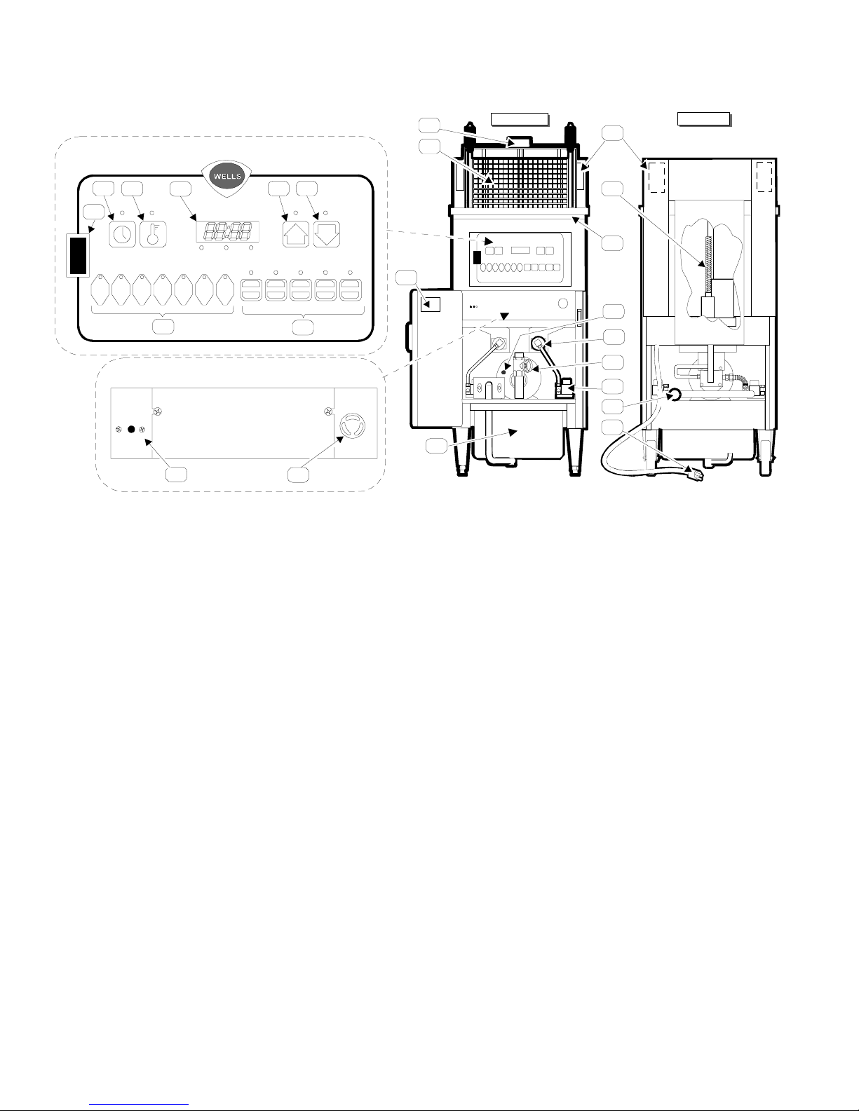
4. Gas pressure must be checked for BOTH burner systems,
while the fryer is in operation. This pressure is measured
by connecting a manometer to the pressure tap on the
gas control valve (pressure tap is threaded 1/8” NPT) :
a. Press the power switch to OFF. Turn the gas
shut-off valve for that side OFF.
b. Remove the pressure tap plug and insert an
appropriate manometer.
c. Turn the gas shut-off valve ON, and press the
power switch to FRYER.
d. Read the manometer while the gas control valve
is energized.
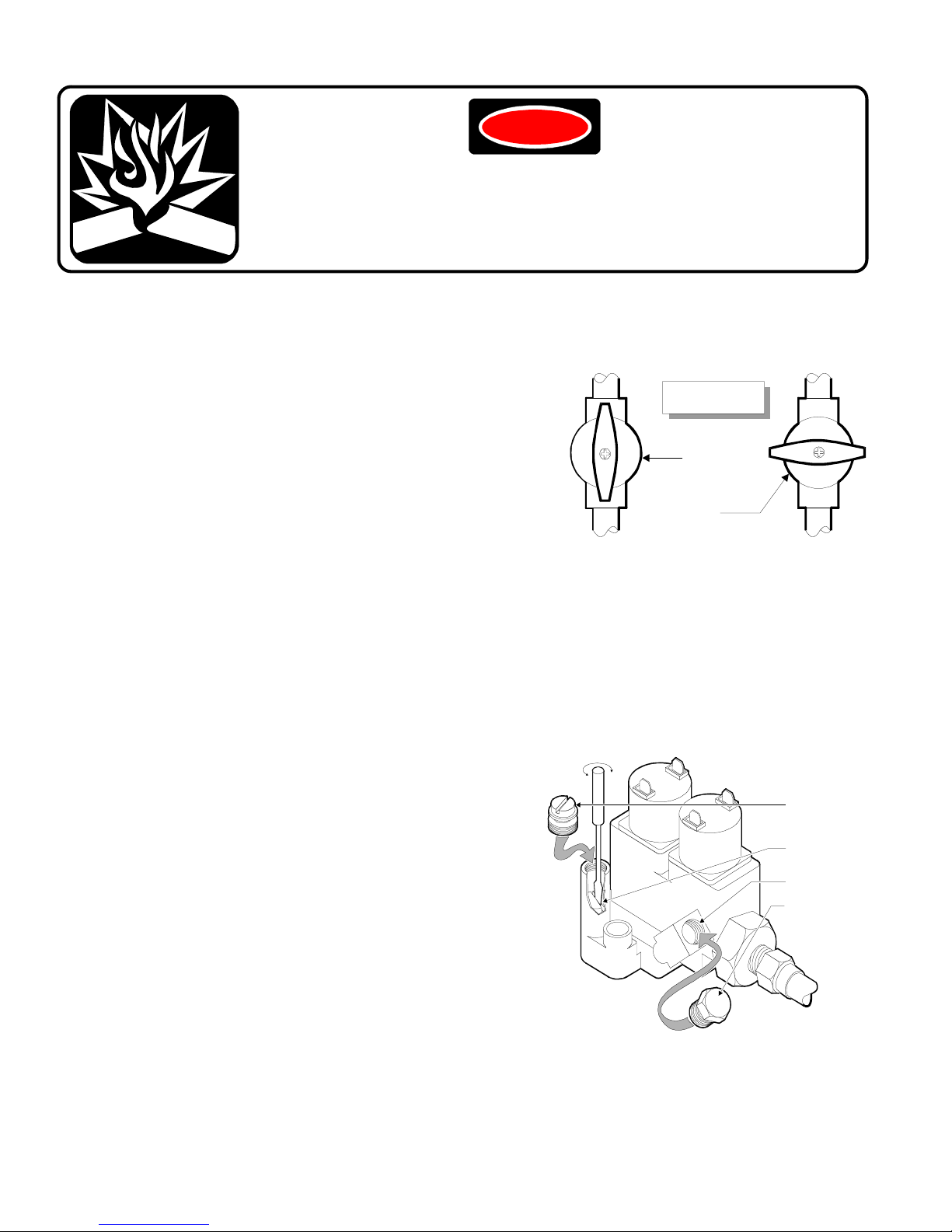
5. If adjustment is necessary, remove the regulator seal
screw and, using a small, flat-blade screw driver, turn
the adjusting screw (inside).
6. Be sure to turn the gas shut-off valve OFF prior to removing the
manometer. Replace the regulator seal screws and pressure tap
plugs for BOTH gas valves before turning the gas shut-off valves ON.
DANGER
FIRE AND EXPLOSION HAZARD
GAS CONNECTIONS AND GAS ADJUSTMENTS MUST BE MADE BY
A LICENSED PLUMBER, CERTIFIED IN GAS INSTALLATION
A gas explosion will cause death or serious injury.
PRESSURE TAP
PRESSURE TAP
PLUG
PRESSURE
REGULATOR
ADJUSTMENT
REGULATOR
SEAL SCREW
GAS SHUT-OFF
VALVE
OPEN POSITION
()ON
CLOSED POSITION
()OFF

D. NATURAL GAS / LP GAS (PROPANE) CONVERSION
1. This fryer is orificed at the factory for natural gas at a pressure of 3.5” of water column.
The installed orifice is suitable for use at -280 to 2999 feet (-85 to 914 meters) elevation.
It is the responsibility of the installer to install the factory recommended orifice and pressure
regulator kit suitable for the fuel type and elevation at the final installation site.
2. The red tag (p/n 301217) attached to the gas connection provides pressure settings and part
numbers for conversion kits applicable to various fuels and altitudes.
3. The natural gas altitude conversion kit contains
two orifices. Both orifices must be changed.
Be sure to use a back-up wrench when
changing orifices to avoid bending the
orifice bracket on the burner tube.
Be sure to check operating pressures on both
burner systems after the orifices have been
changed.
4. The LP gas (propane) conversion set contains
two orifices and two gas valve regulator kits.
Both orifices must be changed, and both
gas valve regulators must be converted.
Complete instructions are included in the
regulator conversion kits. Be sure to check
and adjust operating pressures on both burner
systems after the orifices have been changed
and the regulators have been converted.
NOTE: Failure to install proper orifices can potentially cause burner and flue system failure.
Damaged caused by improper orifice installation is NOT covered by warranty.
E. FLAME ADJUSTMENT
1. A proper flame will have a bright blue, well defined inner cone, and a strong,
light blue outer cone with only a very little yellow along the outermost edges.
2. Too much yellow indicated a rich flame. Adjust by opening the shutter or
decreasing the orifice size (see tag p/n 301217 for proper orifice size for the
installation altitude).
3. No yellow and a very small inner cone indicates a lean flame. Adjust by
closing the shutter or increasing the orifice size (see tag p/n 301217 for
proper orifice size for the installation altitude).
7
REGULATOR SEAL SCREW
(USE NEW ITEM FROM KIT)
REGULATOR SPRING
(USE NEW ITEM FROM KIT)
ADJUSTMENT SCREW
(REUSE EXISTING ITEM)
BURNER
TUBE
OUTER
CONE
INNER
CONE
35. ORIFICE HOLDER
6. ORIFICE WASHER
8. or 27. BURNER
14. ORIFICE
NOTE: ORIFICE
SIZE MARKING
PLACE BACK-UP WRENCH ON THIS
SIDE WHEN CHANGING
ORIFICE
PLACE BACK-UP WRENCH ON THIS SIDE
WHEN TIGHTENING
GAS SUPPLY TUBE

8
OPERATION
A. HEATING INSTRUCTIONS
IMPORTANT: Never press the POWER SWITCH to FRYER unless the frypot is filled with
shortening. Check shortening level marker inside the frypot for proper shortening level.
NOTE: The fryer is designed to be used with LIQUID SHORTENING only. Lard and solid
shortening will solidify in thefilter pump, causing pump failure.
1. Program MENU KEY times and temperatures (see IOM Manual, p/n 301198).
2. Press POWER SWITCH to FRYER position.
a. The controller will energize the GAS CONTROL VALVES and the IGNITORS.
b. The GAS CONTROL VALVES will remain energized for 4 seconds while the flame
sensor proves the flame.
c. At the end of the 4 second period, if flame has not been sensed, the gas valve will
de-energize for 30 seconds. The controller will attempt three times to establish a flame.
d. If flame cannot be established in three tries, the controller will lock out. The power
switch must be pressed to OFF, then back to FRYER to release the lock out.
e. If flame is sensed within the 4 second proving period, the GAS CONTROL VALVES
will remain energized and the burners will continue to heat until the shortening has
reached the programmed temperature. The readout will display “PRE” and “HEAT” and
the selected MENU KEY, and the HEAT indicator will be lit until the shortening has
reached temperature.
3. When the readout displays “00:00”, the fryer is ready to begin cooking.
B. COOKING INSTRUCTIONS
1. Load frozen product into the BASKET. Using the plastic-coated handles, set the BASKET
on the LIFT CRADLE. Press the “BASKET” KEY followed by the “DOWN ARROW” KEY.
When the cradle if fully lowered, press the desired MENU KEY.
2. For fresh product, lower the basket and hand drop product just above the oil level to prevent
splashing.
IMPORTANT: Different products contain different amounts of moisture, which will
cause the hot oil to foam. Determining the maximum safe load size that will prevent
hazardous overflow and splatter of hot oil. This can be accomplished by starting
with a small load, and gradually increasing the load size until the maximum load
which can be cooked without the oil foaming over the top of the frypot is reached.
3. At the completion of the timed cycle, the cradle will rise and the sonalert will sound.
The BASKET and the cooked product will be hot.
Contact with hot cooked product can cause serious injury.
4. Use the plastic-coated handles to remove the BASKET and dump the cooked product into
a suitable tray or container.

TROUBLESHOOTING OPERATIONAL PROBLEMS
NOTE: The fryer has two independent burner systems, whose only common components are in
the control system (CONTROLLER, TEMPERATURE PROBE and HI-LIMIT THERMOSTAT).
Troubleshooting efforts should isolate a problem to either: an individual burner system; or, to the
control system.
PROBLEM POSSIBLE CAUSE SOLUTION
READOUT not lit POWER SWITCH not Press POWER SWITCH
(Fryer not operating) in FRYER position to FRYER position
Circuit breaker OFF or tripped Reset circuit breaker
Service wiring problem Correct service wiring
Controller connection faulty Check / replace connector
(Fryer operating norm.) CONTROLLER defective Replace CONTROLLER
HEAT LIGHT not lit Programmed temperature Raise programmed temperature
(READOUT lit and too low / select another MENU KEY
Cooking oil cold) CONTROLLER defective Replace CONTROLLER
HI-LIMIT THERMOSTAT Allow oil to cool
TRIPPED Reset HI-LIMIT
COOKING OIL COLD BURNER SYSTEM problem Correct burner problem
(HEAT light lit) Wiring problem / loose connection Correct wiring problem
Defective PROBE Replace PROBE
CONTROLLER defective Replace CONTROLLER
CRADLE LIFT won’t Improper key strokes Press”BASKET” then “DOWN
lower ARROW”
BASKET "DOWN" RELAY defective Replace RELAY
LIFT MOTOR defective Replace LIFT MOTOR
Wiring problem / loose connection Correct wiring problem
CONTROLLER defective Replace CONTROLLER
CRADLE LIFT won’t READOUT not “00:00” or “PAUSE” Press “PAUSE” + “UP ARROW”
raise BASKET "UP" RELAY defective Replace RELAY
LIFT MOTOR defective Replace LIFT MOTOR
Wiring problem / loose connection Correct wiring problem
CONTROLLER defective Replace CONTROLLER
BUZZER does not Buzzer programmed OFF Contact factory for instructions
sound BUZZER defective Replace BUZZER
Wiring problem / loose connection Correct wiring problem
CONTROLLER defective Replace CONTROLLER
BUZZER not loud enough BUZZER SHUTTER closed Open SHUTTER
MENU KEY does not MENU KEY not programmed Program MENU KEY
operate CONTROLLER defective Replace CONTROLLER
FUNCTION KEY does Improper KEY ENTRY Consult OWNERS MANUAL
not operate for proper usage
CONTROLLER defective Replace CONTROLLER
9

10
OIL FILTERING INSTRUCTIONS
DANGER
OIL MUST BE FILTERED WHILE HOT (300ºF AND HIGHER)
Contact with hot oil can cause serious injury including death.
Always wear protective clothing and insulated gloves
when filtering the cooking oil.
1. Refer to the Installation, Operation and Maintenance Manual (p/n 300007) for complete operating
instructions for the filter system. Make certain the FILTER LEAF is properly assembled and
installed.
2. The cooking oil must be hot (minimum of 300º F.) in order to filter properly. Cold oil will not flow
through the filter leaf. Place the POWER SWITCH to the FILTER position. DO NOT turn the
pump ON for more than 10 sec. without oil flowing.
3. Open the DRAIN LEVER. Use the "T"-SHAPED SCRAPER to push crumbs and breading from
the frypot sides down into the bottom of the FRYPOT. The WOOD DOWEL may be used to
unplug the drain hole if necessary.
4. While draining the oil, press the POWER SWITCH to FILTER. Pour the FILTER POWDER into
the oil at the point where it is being drawn down the drain.
5. After all the oil has drained from the FRYPOT, use the HI-TEMP BRUSH to push breading crumbs
and other debris down the drain.
6. After 5 minutes of oil circulation, close the DRAIN VALVE and allow the FRYPOT to fill with
the freshly filtered oil. When all the oil has returned to the FRYPOT, turn OFF the FILTER
SWITCH. Turn the POWER SWITCH to the OFF position until starting to use the fryer again.
7. Allow the FILTER RESERVOIR to cool before servicing. Refer to the IOM Manual (p/n
300007) for complete FILTER RESERVOIR maintenance instructions.
NOTE: Refrain from using soap in the FRYPOT or FILTER RESERVOIR. Soap residue
will cause the cooking oil to breakdown rapidly.
FILTER RAIL “B”
LOWER
FILTER SCREEN
SEPARATOR
UPPER
FILTER SCREEN
FILTER RAIL “A”
STRAIGHT PIN
“L”-SHAPED PIN
TOP VIEW SIDE VIEW

11
TROUBLE SHOOTING - OIL FILTERING PROBLEMS
PROBLEM POSSIBLE CAUSE SOLUTION
FILTER PUMP won’t POWER SWITCH not in Press POWER SWITCH to
run FILTER position FILTER position
PUMP MOTOR OVERLOAD Allow motor to cool, then
tripped press red RESET button on
back of PUMP MOTOR
Defective POWER SWITCH Replace SWITCH
PUMP will not pump SUCTION TUBE not seated in Make sure FILTER RESER-
cooking oil SUCTION RECEPTACLE VOIR is properly installed
SUCTION TUBE O-RING Replace O-RING with one of
missing or damaged the three spares in groove
Damaged SUCTION TUBE Replace damaged
or SUCTION RECEPTACLE components
FILTER LEAF clogged Scrape crumbs and other
debris from FILTER LEAF
Service FILTER RESERVOIR
at next opportunity.
PUMP CHECK VALVE plugged Clean CHECK VALVE
or reversed Install CHECK VALVE properly
PUMP pumps lots of SUCTION TUBE not seated in Make sure FILTER RESER-
bubbles in cooking oil SUCTION RECEPTACLE VOIR is properly installed
SUCTION TUBE O-RING Replace O-RING
missing or damaged
Insufficient oil entering or in Incrementally open DRAIN
FILTER RESERVOIR VALVE and/or clear crumbs
and other debris from DRAIN
PUMP MOTOR tripped PUMP jammed with debris Unjam PUMP
won’t reset Defective PUMP HEAD Replace PUMP HEAD
Defective PUMP MOTOR Replace MOTOR only
Oil is not being filtered FILTER LEAF O-RING missing, Properly install FILTER LEAF
completely damaged or LEAF mis-installed
FILTER LEAF surface clogged AFTER OIL COOLS remove
with debris FILTER LEAF, disassemble
and clean.

12
SERVICING INSTRUCTIONS
GAS DISTRIBUTION AND BURNER SYSTEM
8
27
43
44
6
6
14
14
35
35
12
12
97
97
60
60
11
11
92
92
92
92 61
61
42
42 90
90 46
46
93
45
45
62
87
63
63
a
a

13
ITEM DESCRIPTION SERVICE PART NO.
6 WASHER, ORIFICE
8 BURNER ASSY, LEFT 500781
11 COMBINATION GAS VALVE 500784
12 TUBE, GAS 500802
14 ORIFICE, GAS BURNER
NATURAL GAS, BELOW 3000 FT (2 EA, KIT) 502140
NATURAL GAS, 3000 - 5999 FT (2 EA, KIT) 502141
NATURAL GAS, 6000 - 8999 FT (2 EA, KIT) 502142
NATURAL GAS, ABOVE 9000 FT (2 EA, KIT) 502143
PROPANE, BELOW 2000 FT (2 EA, KIT) 502144
PROPANE, 2000 - 6999 FT (2 EA, KIT) 502145
PROPANE, ABOVE 7000 FT (2 EA, KIT) 502146
27 BURNER ASSY, RIGHT 500980
35 ELBOW, ORIFICE HOLDER
42 VALVE, GAS SHUT-OFF 501592
43 IGNITOR ASSY, RIGHT 501198
44 IGNITOR ASSY, LEFT 501197
45 BRACKET, REAR
46 BRACKET, SIDE
60 ADAPTER, 1/2" NPT x 1/4" COMP.
61 UNION, 1/2" NPT
62 "TEE", 1/2" NPT
63 ELBOW, 90º 1/2" NPT
87 NIPPLE, 1/2" NPT x 2"
90 NIPPLE, 1/2" NPT x 15"
92 NIPPLE, 1/2" NPT x CLOSE
93 NIPPLE, 1/2" NPT x 7"
97 ELBOW, STREET 90º 1/8" NPT BRASS
a PLUG, 1/8"MPT (part of 500784)

BURNER ASSEMBLY INSTRUCTIONS
A. ORIFICE INSTALLATION
1. Slide the brass ORIFICE through the ring on the
end of the BURNER, threaded end pointing out.
2. Slide the ORIFICE WASHER over the threads
of the ORIFICE.
3. Screw the ORIFICE HOLDER on to the ORIFICE.
Tighten the orifice holder so that the compression
fitting sits pointing toward the outside and down at
a 30º angle.
4. Always use a back-up wrench when tightening
the orifice to avoid bending the orifice bracket.
B. SHUTTER ADJUSTMENT
1. This is an initial adjustment. Final adjustment
will be made while the burner is in operation.
2. Loosen the holding screw. Set the shutter so
that 1/8" of the shutter is exposed.
Tighten the screw.
C. BURNER TUBES
1. BURNER TUBES are handed right and left.
Visually, the row of burner slots point up and
slightly inward. Also, the tops of the rear
mounting tabs slant toward the center.
D. IGNITOR ASSEMBLY
1. IGNITORS are handed right and left. Visually:
a. Right: The flame sensor (right probe) is
bent at a 90º angle;
b. Left: The flame sensor (right probe) is
nearly straight.
2. When properly assembled, all three probes will
lay on a line drawn from the center of the burner
tube through the center of the burner slots.
3. All three probes should be .5" from the outer
surface of the burner slots.
4. The gap between the ignitor and ground probes
must be .10".
5. To insure proper ignition, the gap between the
ignitor and ground probes must be directly in
the gas stream.
6. To insure proper flame detection, the tip of the
flame sensor probe must be directly in the gas
stream.
14
ORIFICE HOLDER
ORIFICE WASHER
BURNER
ORIFICE
30º
SHUTTER
BACK-UP
WRENCH

E. BURNER INSTALLATION
1. Insert each BURNER TUBE through its respective mounting plate.
2. CAREFULLY reach inside the unit, just above the filter pump heat shield, to guide the rear
mounting tab of the burner tube into the slot in the rear mounting bracket.
3. Slide the the burner assembly over the front mounting studs, thread on nuts and tighten.
15
REAR MOUNTING
SLOT
FRONT MOUNTING
PLATE
REAR MOUNTING BRACKET
REAR MOUNTING TAB
FRONT MOUNTING
BRACKET
RIGHT-HAND
BURNER ASSY

CRADLE LIFT ASSEMBLY
ITEM DESCRIPTION SERVICE PART NO.
1 BEARING, ROLLER .75OD x .25ID (pk6) 500031
2 CRADLE PIVOT ASSEMBLY
4 ROD, LIFT
5 BASKET, FRYER 22441
34 ACTUATOR, LIFT 69812
71 CLAMP, PLASTIC 3/8” DIA.
82 YOKE, ROD LIFT
83 BASKET CRADLE LIFT ASSEMBLY
84 BUSHING, LIFT ROD 69972
J NUT, ACORN 1/4-20 SS
K BOLT, HEX 1/4-20 x 34” SS
L LOCK WASHER 1/4” SS
M BOLT, HEX 1/4-20 x 1/2” SS
P SCREW, HEX 3-32 x 1/2”
R WASHER .265 ID x .50 OD SS
S SET SCREW, 1/4-20 x 5/16”
U JAM NUT, 1”-14 UNF
V WAVE WASHER, 1”
Y SET SCREW, 1/4-20 x 5/8”
2
S
84
V
U
34
71
M
P
4
82
Y
5
83
K
R
1
L
J
BASKET AND CRADLE LIFT
16

LIFT MOTOR / LIFT ROD
ASSEMBLY INSTRUCTIONS
A. LIFT ROD BUSHING
1. The top bushing assembles through the TOP PANEL and
FRAME. The WAVE WASHER and JAM NUT go BELOW
top part of frame.
2. The bottom bushing assembles through the top hole in the
FRAME BACK PANEL.
B. LIFT MOTOR
1. Apply voltage to the BLACK and WHITE wires of the motor
until the screw stops turning. This is the full-down position.
Turn the BRASS NUT until the distance from the top of the
nut to the top of the screw is 10-1/4” to 10-3/8”.
2. Assemble the LIFT MOTOR to the MOTOR MOUNT
PLATE with four bolts and threadlock.
C. CRADLE PIVOT
1. Assemble the CRADLE PIVOT to the LIFT ROD.
2. The SET SCREW on the PIVOT COLLAR must be
centered on the flat on the LIFT ROD.
D. LIFT ROD YOKE
1. Slide the fingers of the YOKE over the flats of the BRASS
NUT. The set screws must be on the side away from the
motor.
2. Slide the PIVOT / LIFT ROD through the top BUSHING,
YOKE, bottom BUSHING and LIFT ROD GUARD. The
CRADLE PIVOT must be parallel to the rear portion of the
TOP PANEL, with the downturned lip of the PIVOT toward
the front of the fryer.
3. Center the YOKE on the flats of the BRASS NUT, then
tighten the YOKE SET SCREWS on the flat on the LIFT
ROD.
4. Apply voltage to the motor leads and carefully observe the
end points of the up-and-down motion. The yoke must clear
the bushings: adjust by loosening the yoke set screws and
“bumping” the lift motor as required by applying voltage
momentarialy to the appropriate motor leads. Tighten the
set screws and re-test for proper up-and-down operation.
A
A
C
D
B
TOP PANEL
FRAME
LIFT ROD
BUSHING
LIFT ROD
BUSHING
YOKE
LIFT ROD
LIFT
MOTOR
FRAME
BACK PLATE
MOTOR
MOUNT
PLATE
17

ITEM DESCRIPTION SERVICE PART NO.
9 IGNITION CONTROL, DIRECT SPARK 500782
10 TRANSFORMER, 120V - 240V 500783
13 PANEL, UPPER CONTROL
18 CONTROLLER, RED LED's 500830
30 THERMOWELL, HI-LIMIT 501158
31 "J" THERMOCOUPLE 501199
32 TRANSFORMER, CONTROLLER 120V - 24V 501201
68 THERMOSTAT, HI-LIMIT 502469
79 SWITCH, POWER FRYER-OFF-FILTER 69550
100 SOLID STATE RELAY 501200
101 RELAY, 24V 501204
102 COOLING FAN 503131
103 SPARK QUENCHER 500688
104 TERMINAL BLOCK, 6P 50578
105 SONALERT 500974
114 FACEPLATE, WELLS 502417
N NUT, ALUMINUM 8-32 x 7/8"
CC ADAPTER, 6-32M x 6-32F
ELECTRICAL COMPONENTS
100
9
10
101
32
9
102
100
101
10
103
18
13
11 4
79
103
104
N
68
31
30
105
CC
18
Other manuals for WFGA-60FS
2
Table of contents
Other Wells Fryer manuals

Wells
Wells WFPE-30F User manual

Wells
Wells Model LLF-14 User manual

Wells
Wells WVAE-30F User manual

Wells
Wells F-676 User manual

Wells
Wells WFAE-30F User manual

Wells
Wells F-886 Configuration guide

Wells
Wells WFAE-55F User manual

Wells
Wells F014 Original operating manual

Wells
Wells WFGA-60FS User manual

Wells
Wells WFPE-68KFC Installation guide

Wells
Wells WFAE-30FEU Instruction Manual

Wells
Wells WVPE-30F Configuration guide

Wells
Wells F-586 User manual

Wells
Wells WVF886 Series User manual

Wells
Wells WVF886 Series Configuration guide

Wells
Wells F-49 Instruction Manual

Wells
Wells WFAE-30F User manual

Wells
Wells F-556 STS User manual

Wells
Wells WFAE-30F Guide

Wells
Wells PL507 User manual