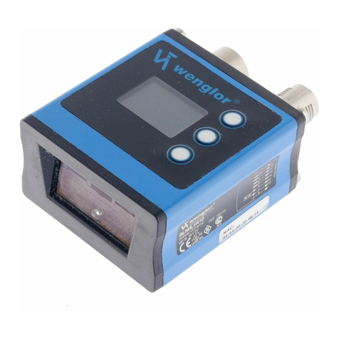
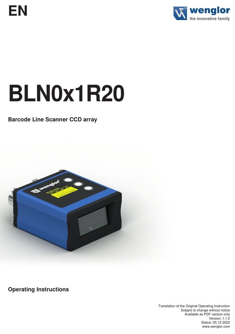
Wenglor BLN0 1R20 Series User manual

BLN0x1R20
Barcode Line Scanner CCD array
Operating Instructions
EN
Translation of the Original Operating Instruction
Subject to change without notice
Available as PDF version only
Version: 1.0.1
Status: 11.11.2020
www.wenglor.com

2Index
Index
1. General 5
1.1. Information Concerning these Instructions 5
1.2. Explanations of Symbols 5
1.3. Limitation of Liability 6
1.4. Copyrights 6
2. For Your Safety 7
2.1. Use for Intended Purpose 7
2.2. Use for Other than the Intended Purpose 8
2.3. Personnel Qualifications 8
2.4. Modification of Products 8
2.5. General Safety Precautions 8
2.6. Approvals and protection class 9
3. Technical Data 10
3.1. Scanner Connection 11
3.2. Housing Dimensions 12
3.3. Control Panel 12
3.4. Complementary Products (see catalog) 13
4. Mounting Instructions 14
5. Initial Operation 14
5.1. Initial Operation 14
6. Function Descriptions 15
6.1. Run 17
6.2. Pin Function 17
6.3. E/A Settings 17
6.3.1. Output – NPN/PNP 19
6.3.2. Output – NO/NC 19
6.3.3. Output – ON Delay 20
6.3.4. Output – OFF Delay 20
6.3.5. Output – Pulse Length 21
6.4. E/A Test 21
6.4.1. E/A Test – Testing A1 through A4 21
6.4.2. E/A-Test – Testing E1 through E4 22
6.5. Reading mode 22
6.6. Code Settings 23
6.7. Match code 23
6.8. Interface 23
6.8.1. Serial/Baude rate 24

3
1D/2D and Barcode Scanners
6.8.2. Ethernet 24
6.8.2.1. IP-address 24
6.8.2.2. Subnet mask 24
6.8.2.3. Standard Gateway 25
6.8.2.4. DHCP 25
6.8.2.5. MAC Address 25
6.8.2.6. Network Reset 25
6.8.2.7. Accept 25
6.8.2.8. Cancel 25
6.9. Display 26
6.9.1. Display – Mode 26
6.9.2. Display – Intensity 26
6.10. Language 27
6.11. Info 27
6.12. Reset 27
6.13. Password 27
7. Network Settings 28
8. Web-Based Configuration 28
8.1. Invoking the Administration Interface 28
8.2. Overview Page 29
8.3. Device Settings 30
8.4. Read Cycle 33
8.4.1. Reading mode 33
8.4.2. Read timeout 33
8.4.3. Code 34
8.4.4. Preamble and Postamble Characters 34
8.4.5. Match code Parameters 34
8.4.6. Terminator 35
8.4.7. Match code 35
8.4.8. Current Match code 35
8.4.9. Match and Mismatch Performance 35
8.5. Code Settings 36
8.5.1. Code 39 36
8.5.2. Code 11 36
8.5.3. Code 128 36
8.5.4. Interleaved 2 of 5 37
8.5.5. Codabar 37
8.5.6. UPC/EAN 37
8.5.7. Code 93 37
8.5.8. Industrial 2 of 5 37
8.5.9. MSI Code 37
8.5.10. RSS-14 Expanded 37

5
1D/2D and Barcode Scanners
1. General
1.1. Information Concerning these Instructions
• These instructions apply to the product with ID code BLN0x1R20.
• They make it possible to use the product safely and efficiently.
• These instructions are an integral part of the product and must be kept on hand for the entire duration of its
service life.
• Local accident prevention regulations and national work safety regulations must be complied with as well.
• The product is subject to further technical development, and thus the information contained in
these operating instructions may also be subject to change. The current version can be found at
www.wenglor.com in the product’s separate download area.
NOTE!
The operating instructions must be read carefully before using the product and must be
kept on hand for later reference.
1.2. Explanations of Symbols
• Safety precautions and warnings are emphasized by means of symbols and attention-getting words
• Safe use of the product is only possible if these safety precautions and warnings are adhered to
• The safety precautions and warnings are laid out in accordance with the following principle:
ATTENTION-GETTING WORD!
Type and Source of Danger!
Possible consequences in the event that the hazard is disregarded.
• Measures for averting the hazard.
The meanings of the attention-getting words, as well as the scope of the associated hazards, are listed below.
DANGER!
This word indicates a hazard with a high degree of risk which, if not avoided, results in
death or severe injury.
WARNING!
This word indicates a hazard with a medium degree of risk which, if not avoided, may result
in death or severe injury.
CAUTION!
This word indicates a hazard with a low degree of risk which, if not avoided, may result in
minor or moderate injury.
ATTENTION!
This word draws attention to a potentially hazardous situation which, if not avoided, may
result in property damage.
6General
NOTE!
A note draws attention to useful tips and suggestions, as well as information regarding
efficient, error-free use.
1.3. Limitation of Liability
• The product has been developed in consideration of the current state-of-the-art and applicable standards
and guidelines. Subject to change without notice.
• A valid declaration of conformity can be accessed at www.wenglor.com in the product’s separate download
area.
• wenglor sensoric elektronische Geräte GmbH (hereinafter referred to as “wenglor”) excludes all liability in
the event of:
• Non-compliance with the instructions
• Use of the product for purposes other than those intended
• Use by untrained personnel
• Use of unapproved replacement parts
• Unapproved modification of products
• These operating instructions do not include any guarantees from wenglor with regard to the described pro-
cedures or specific product characteristics.
• wenglor assumes no liability for printing errors or other inaccuracies contained in these operating instructions,
unless wenglor was verifiably aware of such errors at the point in time at which the operating instructions
were prepared.
1.4. Copyrights
• The contents of these instructions are protected by copyright law.
• All rights are reserved by wenglor.
• Commercial reproduction or any other commercial use of the provided content and information, in particular
graphics and images, is not permitted without previous written consent from wenglor.

7
1D/2D and Barcode Scanners
2. For Your Safety
2.1. Use for Intended Purpose
This wenglor product has to be used according to the following functional principle:
Scanner 1D
These Scanners detect 1D Codes with the help of Laser Light respectively Red Light. The light sent out to the
barcode label is reflected back to a photo element and evaluated with a decoder.
This product can be used in the following industry sectors:
• Automotive industry
• Food industry
• Packaging industry
• Pharmaceuticals industry
• Clothing industry
• Plastics industry
• Consumer goods industry
• Paper industry
• Electronics industry
• Glass industry
• Printing industry
• Special machinery manufacturing
• Heavy machinery manufacturing
• Logistics
• Woodworking industry
• Steel industry
• Aviation industry
• Construction industry
• Chemicals industry
• Agriculture Industry
• Alternative energy
• Raw materials extraction

8For Your Safety
2.2. Use for Other than the Intended Purpose
• Not a safety component in accordance with 2006/42/EC (Machinery Directive)
• The product is not suitable for use in potentially explosive atmospheres.
• The product may only be used with accessories supplied or approved by wenglor, or combined with
approved products. A list of approved accessories and combination products can be accessed at
www.wenglor.com on the product detail page.
DANGER!
Risk of personal injury or property damage in case of use for other than the intended
purpose!
Use for other than the intended purpose may lead to hazardous situations.
• Observe instructions regarding use for intended purpose.
2.3. Personnel Qualifications
• Suitable technical training is a prerequisite
• In-house electronics training is required
• Trained personnel must have uninterrupted access to the operating instructions
DANGER!
Risk of personal injury or property damage in case of incorrect initial start-up and
maintenance!
Personal injury and damage to equipment may occur.
• Adequate training and qualification of personnel.
2.4. Modification of Products
DANGER!
Risk of personal injury or property damage if the product is modified!
Personal injury and damage to equipment may occur. Non-observance may result in loss
of the CE marking and the guarantee may be rendered null and void.
• Modification of the product is impermissible.
2.5. General Safety Precautions
• This operating instruction is part of the product and must be kept during its entire service life.
• Read this operating instruction carefully before using the product.
• Installation, start-up and maintenance of this product has only to be carried out by trained personal.
• Tampering with or modifying the product is not permissible.
• Protect the product against contamination during start-up.
• Not a safety component in accordance with the EU Machinery Directive.

9
1D/2D and Barcode Scanners
2.6. Approvals and protection class
WARNING!
This is a class A device. This device may cause radio interference in residential areas. If this
is the case, the implementation of appropriate measures may be demanded of the user.

10 Technical Data
3. Technical Data
Order Number BLN0L1R20 BLN0L1H20
Light Source Red Light Red Light
Wave Length 625 nm 625 nm
Long Range yes
Wide Angle yes
Read Range 30…520 mm 20…200 mm
max. Ambient Light 70000 Lux 70000 Lux
Opening Angle 40° 65°
Barcode Label Contrast > 30 % > 30 %
Supply Voltage 18...30 V DC 18...30 V DC
Current Consumption (Ub = 24 V) < 100 mA < 100 mA
Scan rate 510 scan/s 510 scan/s
Temperature Range –20…60 °C –20…60 °C
Inputs/Outputs 4 4
Switching Output Voltage Drop < 2,5 V < 2,5 V
Switching Output/Switching Current 100 mA 100 mA
Short Circuit Protection yes yes
Ports Reverse Polarity Protection yes yes
Ports Overload Protection yes yes
Interface RS-232*/Ethernet RS-232*/Ethernet
Housing Aluminum Aluminum
Protection Class III III
Protection IP67 IP67
Connection M12×1 M12×1
Baud Rate 10 Mbit/s / 100 Mbit/s 10 Mbit/s / 100 Mbit/s
Transmission Mode Full- /Half Duplex Full- /Half Duplex
Webserver yes yes
Default IP 192.168.100.1 192.168.100.1
Auto-Crossover yes yes
Auto-Negotiating yes yes
Auto-Polarity yes yes
* Maximum connection length: 30 m

11
1D/2D and Barcode Scanners
BLN0L1R20
Min. Resolution Read Range
0,076 mm – Code 39 (4 digits)
0,101 mm 60…130 mm Code 39 (4 digits)
0,127 mm 55…170 mm Code 39 (4 digits)
0,254 mm 30…350 mm Code 39 (4 digits)
0,381 mm 45…520 mm Code 39 (4 digits)
0,330 mm 40…390 mm UPC/EAN (13 digits)
Scanning field width 200 mm Code39 (0,330 mm)
BLN0H1R20
Min. Resolution Read Range
0,076 mm 35…70 mm Code 39 (13 digits)
0,101 mm 25…80 mm Code 39 (4 digits)
0,127 mm 25…100 mm Code 39 (4 digits)
0,254 mm 20…160 mm Code 39 (4 digits)
0,381 mm 30…200 mm Code 39 (4 digits)
0,330 mm 30…170 mm UPC/EAN (13 digits)
Scanning field width 110 mm Code39 (0,330 mm)
3.1. Scanner Connection
786
Figure 1: Plug 1
002
Figure 2: Plug 2
+ Supply Voltage „+“
– Supply Voltage „0 V“
E/A Output/Input programmable
RxD RS-232 receive path
TxD RS-232 send path
Tx+/– Ethernet send path
Rx+/– Ethernet receive path

12 Technical Data
3.2. Housing Dimensions
3.3. Control Panel
23 20 22
60
X2
20 = Enter Button
22 = Up Button
23 = Down Button
60 = Display

13
1D/2D and Barcode Scanners
3.4. Complementary Products (see catalog)
wenglor offers Connection Technology for field wiring.
Suiting Connection Technology No.
50
89
S80 S74
Connector cable M12×1, 8-pin (plug 1)
S74 ZAS89R201, M12×1 connector cable, 8-pin, 2 m, straight
ZAS89R202, M12×1 connector cable, 8-pin, 2 m, angled
ZAS89R501, M12×1 connector cable, 8-pin, 5 m, straight
ZAS89R502, M12×1 connector cable, 8-pin, 5 m, angled
ZAS89R601, M12×1 connector cable, 8-pin, 10 m, straight
ZAS89R602, M12×1 connector cable, 8-pin, 10 m, angled
ZAS89R701, M12×1 connector cable, 8-pin, 20 m, straight
ZAS89R702 , M12×1 connector cable, 8-pin, 20 m, angled
Interface cable (plug 1)
S10
S232W3 Interface cable, M12×1, 8-pin, 1,5 m, angled
Connector cable M12×1, 8-pin (plug 2)
S80
ZAV50R201, M12×1 connector cable, 8-pin, 2 m
ZAV50R501, M12×1 connector cable, 8-pin, 5 m
ZAV50R502, M12×1 connector cable, RJ45, 5 m

14 Mounting Instructions
4. Mounting Instructions
All applicable electrical and mechanical regulations, standards and safety precautions must be adhered to
when installing and operating the scanner. The scanner must be protected against mechanical influences.
Install the product such that its installation position cannot be inadvertently changed.
5. Initial Operation
5.1. Initial Operation
Connect the Scanner to supply power (18 to 30 V DC). The display view appears. The Scanner is ready for
operation after 2 seconds.
The desired menu language must be selected after initial start-up, and after each reset (see section “6.10.
Language” on page 27).
Note: If no settings are adjusted in the configuration menu for a period of 30 seconds, the scanner is automati-
cally returned to the display mode.
The Scanner accesses the last used menu view when the key is pressed twice. If a setting is configured, it
becomes active as soon as it is changed.
Letters or symbols such as “+” and “–” can also be assigned to the keys within a menu item. Quicker scrolling
through numbers is this made possible by pressing and holding the “+” or “–” key.
Meaning of the menu items:
3Back : Move up one level within the menu.
7Run : Switch to the display mode.

15
1D/2D and Barcode Scanners
6. Function Descriptions
Run
Pin Function
E/A1
E/A2
E/A3
E/A4
Trigger
Trigger Level
Serial Trigger
Continuous
Read timeout
Good Read
No Read
Match
Mismatch
Trigger Input
New Master
At Ub
At 0 V
ON
OFF
PNP
NPN
Pushpull
NO
NC
Value in ms
Value in ms
Value in ms
NPN/PNP
NO/NC
ON Delay
OFF Delay
Impulse
Depends on pin function E/A1:
A1 Good Read
A1 No Read
A1 Match
A 1 Mismatch
E1 Trigger
E1 New Master
Depends on pin function E/A2:
A2 Good Read
A2 No Read
A2 Match
A2 Mismatch
E2 Trigger
E2 New Master
Depends on pin function E/A3:
A3 Good Read
A3 No Read
A3 Match
A3 Mismatch
E3 Trigger
E3 New Master
Depends on pin function E/A4:
A4 Good Read
A4 No Read
A4 Match
A4 Mismatch
E4 Trigger
E4 New Master
Depends on pin function E/A1:
Test A1
Test E1
Depends on pin function E/A2:
Test A2
Test E2
Depends on pin function E/A3:
Test A3
Test E3
Depends on pin function E/A4:
Test A4
Test E4
E/A Test
Reading mode
E/A configure If switching output
If switching output
If input
Run Mode Input
Value in ms
If input

16 Function Descriptions
Code Settings
Matchcode
ON/OFF
New match code
Match code
Serial
Ethernet
Rotate
Intensity
Mode
Display order number,
version and serial
number
Code39
Interleaved2/5
Codabar
Code32
MSI Plessy
Code11
Industrial2/5
Matrix2/5
Telepen
UKPlessy
Code93
EAN-13
EAN-8
UPC-A
UPC-E
Code128
EAN-128
RSS-14
ON
OFF
New match code
is read in
OFF
ON
Password: 0 – 9999
Current matchcode
is displayed
Baude rate
Settings
IP-address
Subnet Mask
Std Gateway
DHCP
MAC Address
Net Reset
Min
Normal
Max
Power save
Screensaver
E/A
Match code
Text
Reading
performance
9600
19200
38400
115200
ON
OFF
Network setting are displayed
Change IP-address
Change Subnet Mask
Change Standard Gateways
Display
Enable
Change
Lock
Password
Deutsch
English
Francais
Espanol
Italiano
Language
Info
Press <R>
for Reset
Reset
Interface

17
1D/2D and Barcode Scanners
Which functions can be executed with the individual menu options is explained below.
6.1. Run
The Scanner is switched to the display mode when the enter key is pressed.
6.2. Pin Function
The pin function is used to specify the function assigned to pins E/A1 through E/A4. Various functions can be
assigned to the pin.
E/A1 Configuration of Pin E/A1
Good Read
No Read
Match
Mismatch
Trigger Input
New Master
3Back
7Run
Good Read: Switching output for successful read.
No Read: Switching output for unsuccessful read attempt (only active in trigger
mode)
Match: Switching output for successful match comparison of a code.
Mismatch: Switching output for match comparison without equivalence.
Trigger Input: Input for triggering the Scanner. The trigger function must be acti-
vated with the reading cycle menu option for trigger mode operation.
Master: Input for reading a new Match code against which comparison will
take place. The next code to be read in becomes a Match code.
6.3. E/A Settings
After selecting the pin function, one of the following menus appears.
Each of the menus includes the following items:
For Good Read
When a pin is configured as a Good Read output, the following functions can be set up:
A1 Good Read/
A2 Good Read/
A3 Good Read/
A4 Good Read
Basic Scanner settings for the individual switching outputs are entered to the
A1/A2/A3/A4 Good Read menu.
NPN/PNP
NO/NC
ON Delay
OFF Delay
Impulse
3Back
7Run
NPN/PNP: Output configuration
NO/NC: Output configuration
ON Delay: ON Delay
OFF Delay: OFF Delay
Impulse: Pulse Length

18 Function Descriptions
For No Read
A1 No Read/
A2 No Read/
A3 No Read/
A4 No Read
Basic Scanner settings for the individual switching outputs are entered to the
A1/A2/A3/A4 No Read menu.
NPN/PNP
NO/NC
ON Delay
OFF Delay
Impulse
3Back
7Run
NPN/PNP: Output configuration
NO/NC: Output configuration
ON Delay: ON Delay
OFF Delay: OFF Delay
Impulse: Pulse Length
For Match
When a pin is configured as a Match output, the following functions can be set up:
A1 Match/
A2 Match/
A3 Match/
A4 Match
Basic Scanner settings for the individual switching outputs are entered to the
A1/A2/A3/A4 Match menu.
NPN/PNP
NO/NC
ON Delay
OFF Delay
Impulse
3Back
7Run
NPN/PNP: Output configuration
NO/NC: Output configuration
ON Delay: ON Delay
OFF Delay: OFF Delay
Impulse: Pulse Length
For Mismatch
When a pin is configured as a Mismatch output, the following functions can be set up:
A1 Mismatch/
A2 Mismatch/
A3 Mismatch/
A4 Mismatch
Basic Scanner settings for the individual switching outputs are entered to the
A1/A2/A3/A4 Mismatch menu.
NPN/PNP
NO/NC
ON Delay
OFF Delay
Impulse
3Back
7Run
NPN/PNP: Output configuration
NO/NC: Output configuration
ON Delay: ON Delay
OFF Delay: OFF Delay
Impulse: Pulse Length

19
1D/2D and Barcode Scanners
For Trigger Input
When a pin is configured as a trigger input, the following functions can be set up:
E1 Trigger/
E2 Trigger/
E3 Trigger/
E4 Trigger
Basic Scanner settings for the individual inputs are entered to the E1/E2/E3/E4
Trigger menu.
At Ub
At 0 V
3Back
7Run
At Ub: The input is activated when supply power (Ub) is on.
At 0 V: The input is activated when supply power is off.
For New Master
When a pin is configured as a New Master input, the following functions can be set up:
E1 New Master/
E2 New Master/
E3 New Master/
E4 New Master
Basic Scanner settings for the individual inputs are entered to the E1/E2/E3/E4 New
Master menu.
At Ub
At 0 V
3Back
7Run
At Ub: The input is activated when supply power (Ub) is on.
At 0 V: The input is activated when supply power is off.
6.3.1. Output – NPN/PNP
NPN/PNP Configuring the outputs
PNP
NPN
Pushpull
3Back
7Run
PNP: A load or an analysis module is connected between the minus pole
(reference) and the output. When switched, the output is connected
to the plus pole via an electronic switch.
NPN: A load or an analysis module is connected between the plus pole
(reference) and the output. When the scanner is switched, the output
is connected to the minus pole via an electronic switch.
Pushpull: Push-pull output.
Works like an electronic switch, which switches the output alternately
to the plus pole or the minus pole.
6.3.2. Output – NO/NC
NO/NC Configuring the outputs
NO
NC
3Back
7Run
NO: Normally open contact, light switching.
The output is deactivated as soon as the set event (Good Read,
Match, Mismatch or No Read) occurs.
NC: Normally closed contact, dark switching.
The output is activated as soon as the set event (Good Read, Match,
Mismatch or No Read) occurs.

20 Function Descriptions
6.3.3. Output – ON Delay
ON Delay is an adjustable extension of response time.
Code
Output
ON Delay
ON Delay Adjusting ON Delay
ON Delay in ms ON Delay can be adjusted within a range of 0 to 1000 ms by pressing the “+”
or “–” key. Quicker scrolling through numbers is made possible by pressing and
holding the respective key.
6.3.4. Output – OFF Delay
OFF Delay is time from the occurrence of an event (e.g. reading a code) until the output is deactivated.
Code
O
utput
OFF Delay
OFF Delay Adjusting OFF Delay
OFF Delay in ms OFF Delay can be adjusted by pressing the “+” or “–” key. Quicker scrolling
through numbers is made possible by pressing and holding the respective key.
This manual suits for next models
2
Table of contents
Other Wenglor Scanner manuals

Wenglor
Wenglor BLN0x1R10 User manual

Wenglor
Wenglor BLN0 1R10 Series User manual

Wenglor
Wenglor BLN0x1R20 User manual

Wenglor
Wenglor CSMH007 User manual

Wenglor
Wenglor CSLH003 User manual

Wenglor
Wenglor CSLH003 User manual

Wenglor
Wenglor FIS-0870 User manual

Wenglor
Wenglor CSHH001 User manual

Wenglor
Wenglor CSMH00 Series User manual