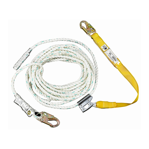
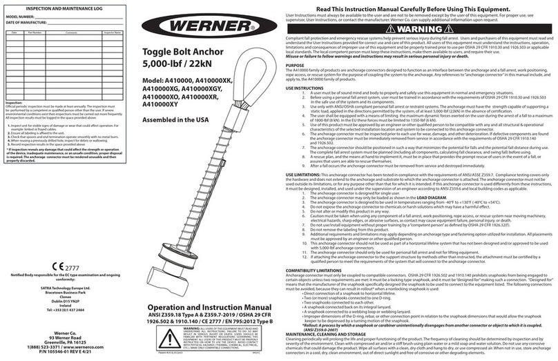
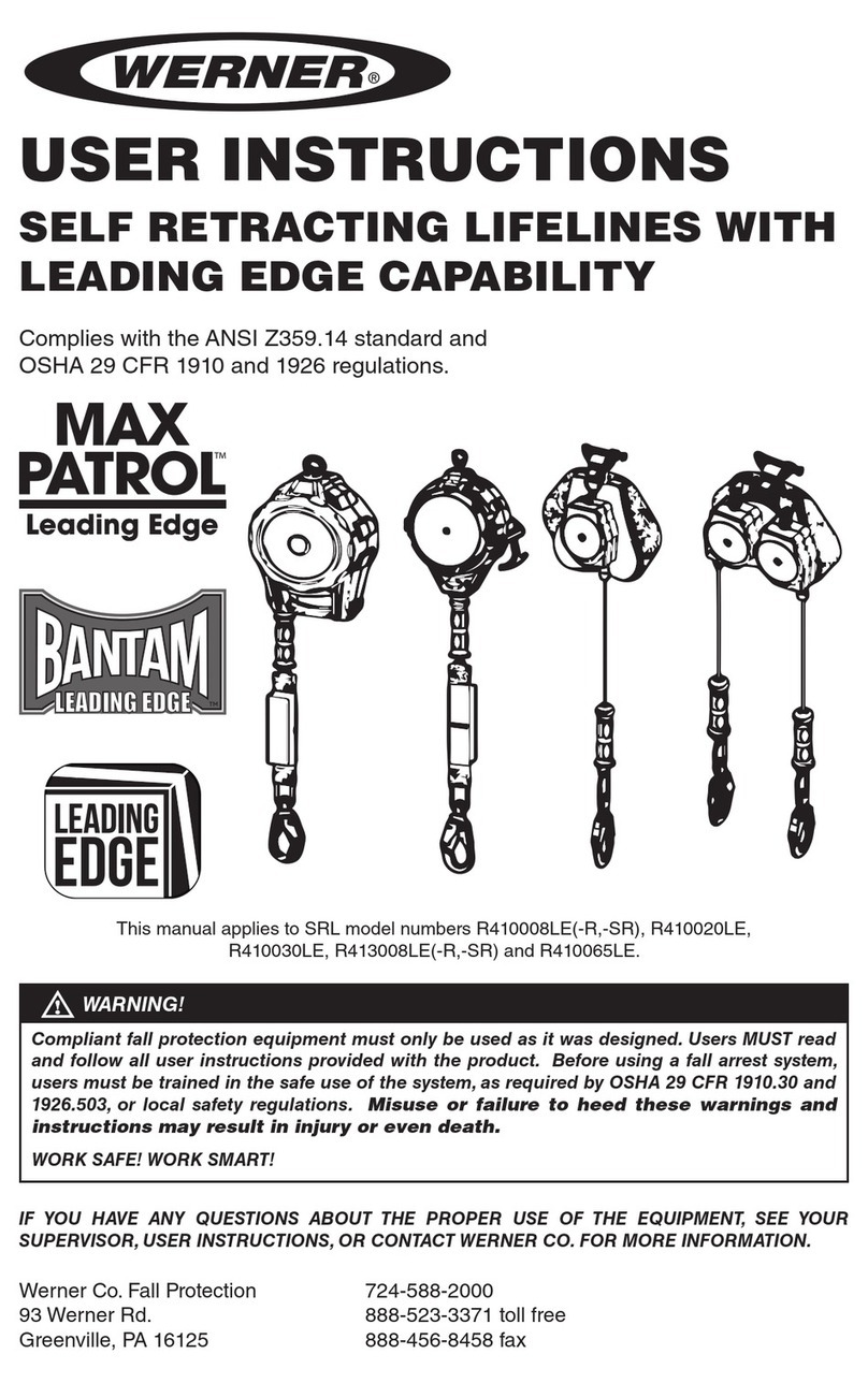
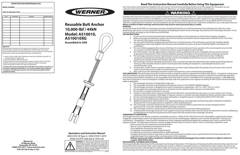
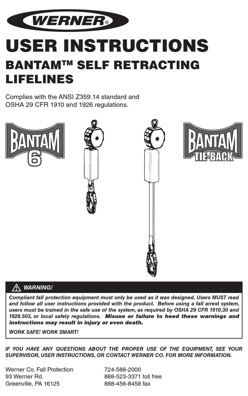
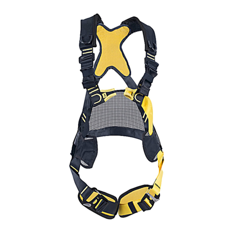
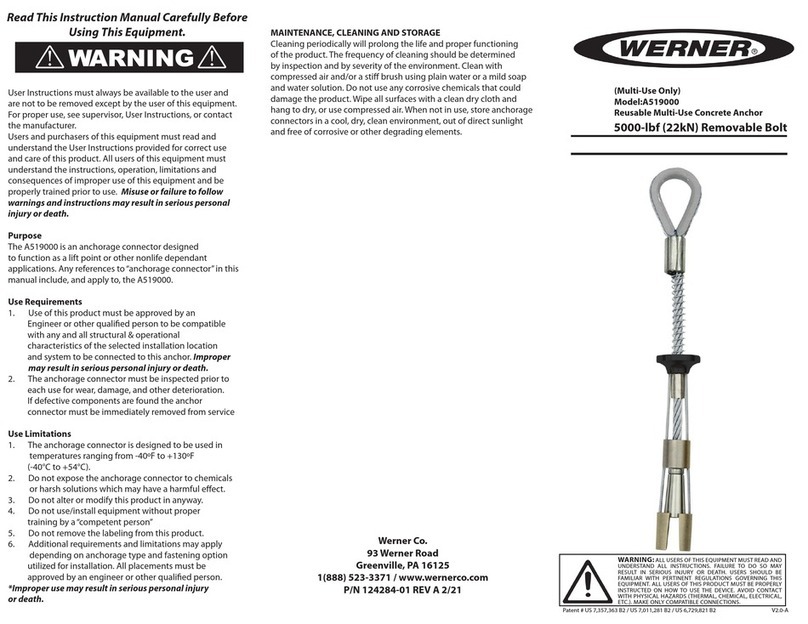
Werner L242350CA Series User manual

ROPE LIFELINE SYSTEM
Complies with CSA Z259.2.5-2012
SYSTÈME DE CORDE DE
SÉCURITÉ
En conformité avec le norme CSA Z259.2.5-2012
Werner Co. Fall Protection 724-588-2000
93 Werner Rd. 888-523-3371 toll free/appel sans frais
Greenville, PA 16125 888-456-8458 fax
(This manual applies to all L242350CA series models.)
(Ce manuel s’applique à tous les modèles de la série L242350CA)
FALL PROTECTION
USER INSTRUCTIONS
PROTECTION CONTRE LES CHUTES
INSTRUCTIONS D'UTILISATION

Page 2
ENGLISH
CAUTION!
If use of fall protection equipment is necessary then the work
environment is dangerous and potentially deadly. Werner Co.products
are designed to eliminate as much of the hazard only as possible but
can do that ONLY if they are used correctly. Use this equipment as it
was designed to be used, after appropriate training, under the direct
supervision of a competent person, according to the instructions
provided, and in accordance with CSA and local safety regulations.
User MUST read and understand all cautions and instructions. Failure
to heed these guidelines could result in injury or even death. WORK
SAFE! WORK SMART!

ROPE LIFELINE SYSTEM
USER INSTRUCTIONS
Page 3
ENGLISH
Contents
WARNINGS ........................................................................................................4
I. BEFORE USING LIFELINE ...............................................................................4
a. Inspect ......................................................................................................................4
b. Compatibility............................................................................................................6
c. Anchorage Strength.................................................................................................6
d. Clearance..................................................................................................................7
e. Rescue Plan..............................................................................................................7
f. Training .....................................................................................................................7
II. PRODUCT DESCRIPTIONS ............................................................................. 7
III.INSTALLATION AND USE................................................................................8
a. Connect the Snap hook...........................................................................................8
b. Connecting to an Anchorage.................................................................................8
c. Connecting the Rope Grab to the Lifeline .............................................................8
IV. USE WARNINGS, RESTRICTIONS AND CAUTIONS .....................................9
a. Adequate anchorages..............................................................................................9
b. Fall Distance ..........................................................................................................10
c. Swing Fall ...............................................................................................................10
d. Capacity..................................................................................................................11
e. Environmental Hazards .........................................................................................11
f. Components/Subsystems.....................................................................................12
g. Care and Storage ...................................................................................................12
V. LABELS/IDENTIFICATION/INSPECTION RECORDS ................................... 12
VI. EQUIPMENT RECORD ................................................................................. 15
VII. INSPECTION RECORDS ............................................................................. 15

Page 4
ENGLISH
Warning:
This product is just one part of a personal fall arrest, work positioning,
travel restraint, climbing or rescue system. It must be matched
correctly with other components to form a complete and functional
system. The user must understand the function of each of these
components and follow the manufacturer’s instructions for use for
each. ANSI, CSA and OSHA standards require that training in the use
of these products be provided by a competent person. The user must
be provided these instructions,should read and follow them,and then
consult the competent person who will supervise his work if he has
any questions about any part of the instructions. The employer must
provide training in the proper use, inspection, and maintenance of all
components in the system,and these instructions can be used as part
of that training. The equipment should be used ONLY in accordance
with these instructions, local ordinances and codes, the applicable
OSHA, CSA and ANSI standards, and the employer’s safety plan.
IF YOU HAVE ANY QUESTIONS ABOUT ANYTHING IN THESE
INSTRUCTIONS, THE EQUIPMENT, OR PROPER USE OF THE
EQUIPMENT, CONTACT WERNER CO. FOR MORE INFORMATION.
I. Before Using the Lifeline
Before using this equipment the user should take certain steps to
ensure that it is in good condition and safe for use.
a. Inspect
Examine all equipment thoroughly, daily before use, and periodically
by a competent person who is not the user. Verify the condition of
each component. If any damage, abnormalities or excessive wear
are found, the product should be removed from service.
1. First check the impact load indicators. For lanyards with shock
packs, the clear plastic cover permits full view. Check the area
near the FALL INDICATOR tag to see if the shock absorbing web
is intact. If there is any indication of impact loading the lanyard
should be removed from service and destroyed. Remove from
service any lanyard which exhibits indications of impact loading.
2. Check the webbing for cuts, abrasions, burns, welding spatter,
or discoloration that could be caused by chemical exposure.

ROPE LIFELINE SYSTEM
USER INSTRUCTIONS
Page 5
ENGLISH
3. Inspect the rope for concentrated wear. The material must be
free of frayed strands, broken yarns, cuts, abrasions, burns,
and discoloration. The rope must be free of knots, excessive
soiling, heavy paint buildup, and rust staining. Rope splices
must be tight, with ve full tucks, and thimbles must be held
by the splice. Cracked or distorted rope thimbles may indicate
that the lifeline has been impact loaded. Check for chemical or
heat damage (indicated by brown, discolored, or brittle areas).
Check for ultraviolet damage, indicated by discoloration and
the presence of splinters and slivers on the rope surface. All of
the above factors are known to reduce rope strength. Damaged
or questionable ropes must be replaced.
4. Check all stitching for any broken threads.
5. Check all hardware for cracks, bends,
irregularities, corrosion, or sharp edges.
Check the snap hook gates for proper smooth
operation.The gates must close and lock and the
primary gate must not open unless the locking
gate is depressed. Ensure the mechanism is
undamaged and functioning properly.
6.Check all plastic parts for damage or cracks.If any abnormalities
are found, the product should be removed from service.
7. Verify that all labels are in place and legible. Examples of
the labels can be found in section V of these instructions.
If abnormalities are found in any of these areas, then the
competent person should be consulted to determine if that item
is safe for continued use or if it should be removed from service.
Warning:
No alteration or modication of any fall protection equipment
is permitted for any reason unless authorized in writing by Werner Co.
LOCKED UNLOCKED

Page 6
ENGLISH
INAPPROPRIATE CONNECTIONS
NO! NO! NO! NO!
NO!NO!NO!NO!
b. Compatibility.
Verify compatibility of all subsystems being used. Werner
products connected to Werner
products should be compatible, but
connection to other products should
be veried for compatibility to ensure
there is no possibility of accidental
detachment from side-loading,
rollout, non-standard closures, etc.
c. Anchorage Strength
Verify that Chosen Anchorages are Appropriate.
1. For fall arrest, anchors need to have strength of either 5,000
lbs. (22.2 kN) per attached user (5000 lbs.) or be certied by a
qualied person to have strength of not less than 3,600 lbs. (16
kN) per attached user.
2. For fall restraint (where there is no possibility of accidental
detachment), anchors need to withstand a static load of 3000
lbs per attached user (13.3kN) or be certied by a qualied
person to be able to withstand two times the foreseeable force.
3. For positioning systems, the anchorage strength must be a
minimum of 3000 lbs (13.3 kN) or be certied by a qualied
person to have strength of twice the foreseeable force.
PROPER CONNECTION

ROPE LIFELINE SYSTEM
USER INSTRUCTIONS
Page 7
ENGLISH
4. For rescue systems, the anchorage should withstand a static
load of 3000 lbs (13.3kN) or be certied by a qualied person
for ve times the foreseeable load.
d. Clearance
Verify that adequate clearance exists below the work area and there
are no objects or obstructions below the work area that the user
could contact in the case of a fall. See section IV for more details.
e. Rescue Plan
If a worker falls and is forced to remain suspended for any length of
time, physical damage to the body or even death can result. For this
reason Werner Co., CSA, OSHA, ANSI and most local regulations
require that a rescue plan and the means to implement the rescue
plan are in place before use of this equipment.
f.Training
OSHA, CSA, ANSI, and most local ordinances require that workers
using this product receive adequate training by a competent person
before use of this product. These instructions and their entire
contents should be a part of that training.
II. Product Descriptions
lanyard (polyester)
shock pack (polyester webbing, PVC protective sleeve)
rope lifeline (polyester/polypropylene)
5,600 lbs. (25 kN) minimum tensile strength
rope grab (alloy steel)
snap hook to harness (alloy steel)

Page 8
ENGLISH
III. Installation and Use
a. Connect the Snap Hook
Connect the snap hook on the lanyard
ONLY to the back D-ring of the harness. Do
not connect to any other part of the harness.
b. Connecting to an Anchorage
Connect the snap hook on the rope
lifeline to the anchor.
Warning:
The rope grab should be positioned to limit potential free fall to the
shortest possible distance, but in no case more than 6’ per CSA Z259
requirements.
c. Connecting the Rope Grab to the Lifeline
Ensure the rope grab is in the “UP” position as indicated on the
device.
NOTE: Keep a minimum distance of 6ft (1.8 m) of rope below the
rope grab for locking distance and fall clearance.
To reposition the rope grab on the life line, lift upward on the
springloaded cam handle that connects the gripping cams. Slide
the rope rab to the desired position on the lifeline and release the
cam handle. The spring-loaded gripping cams will keep the rope
grab in position.
NOTE: The lower end of the lifeline shall have a termination that
prevents the fall arrester from passing through that termination.
When the line is installed, the bottom end shall have a counterweight
to provide stiffness.

Page 9
ENGLISH
Total Fall
Distance
(Free Fall +
Deceleration)
Add Rope Stretch 10% of Rope Length
Free Fall
Working Level
Energy
Absorbing
Lanyard Length of Anchorage Connector
1.8 m (6 ft.)
Length of Lanyard
3.4 m (11 ft.)
1.2 m (4 ft.)
Deceleration Free Fall Distance
0.6 m (2 ft.)
Safety Factor
0.3 m (1 ft.) Harness Stretch
1.5 m (5 ft.)
To Worker’s Back D-Ring
Total Estimated
Fall Distance
+ Rope Stretch
5.5 m (18 ft.)
IV. Use Warnings, Restrictions and Cautions
a. Adequate Anchorages
FALL CLEARANCE: Ensure sufficient clearance exists in your
fall path to prevent striking an
object during a fall.The clearance
required is dependent upon
the subsystem (rope grab and
lanyard, rope grab and carabiner)
and lifeline properties. The chart
to the right shows the approximate
elongation for new Werner Co.
lifelines in dry conditions. The
elongation specied is for an
applied static load of 1,800 lbs
(8 kN). Wet ropes generally have
more elongation than dry ropes.
Allow for additional elongation in
wet or humid conditions. Lifeline
elongation must be considered
when estimating fall clearance.
SHARP EDGES: Avoid working
where your lifeline, lifeline subsystem, or other system components
will be in contact with, or abrade against, unprotected sharp edges.
Do not loop a lifeline around small diameter structural members. If
ROPE LIFELINE SYSTEM
USER INSTRUCTIONS
Lifeline
Length Stretch
10 ft (3 m) 1 ft (0.3 m)
20 ft (6.1 m) 2 ft (0.6 m)
30 ft (9.1 m) 3 ft (1 m)
40 ft (12.2 m) 4 ft (1.2 m)
50 ft (15.2 m) 5 ft (1.5 m)

Page 10
ENGLISH
working with this equipment around sharp edges is unavoidable,
provide protection by using a heavy pad over the exposed sharp
edge.
b. Fall Distance
Contact with a lower level can occur even when this equipment is
in perfect operating condition if there is any object in the path of
a fall or if the height of the anchorage being used is inadequate.
The fall distance can vary according to the connecting subsystem
used. The following sections provide details on how to determine
fall clearances. While these are typical situations, the authorized/
competent person on site should make these determinations for
each work situation depending on the site-specic conditions.
c. Swing Falls
Ensure that there will be no
possibility of a swing-fall impact.
Swing falls occur when the user is
not directly below the anchorage,
so if he falls his swing could
produce an impact with an object.
SWING FALL
HAZARD
Anchorages
CorrectIncorrect
Total Fall
Distance
(Free Fall +
Deceleration)
Free Fall
Working Level
Lower Level or Obstruction
Energy
Absorbing
LanyardLength of Anchorage Connector
6 ft. (1.8 m)
Length of Lanyard
11 ft. (3.4 m)
4 ft. (1.2 m)
Deceleration Free Fall Distance
2 ft. (0.6 m)
Safety Factor
1 ft. (0.3 m) Harness Stretch
5 ft. (1.5 m)
To Worker’s Back D-Ring
Total Estimated
Fall Distance
18 ft. (5.5 m)
Fall distance for shock absorbing lanyards

ROPE LIFELINE SYSTEM
USER INSTRUCTIONS
Page 11
ENGLISH
d. Capacity
Max imum capacity for this product is 254 lbs (115 kg) for the
combined weight of a worker and all tools. For any weight over 254
lbs (115 kg) contact Werner Co. for more information.The employer
should ensure that all other elements of the fall protection system
are adequate to support any higher weights.
e. Environmental Hazards
This equipment is used only under the direct supervision of a
competent person who is able to identify hazards that must be
avoided including electrical and chemicals, machinery or other
moving objects, sharp edges, damaged anchorages or structures,
or any other workplace element that could damage this equipment
or prevent it from operating as intended.
1. CORROSION: Do not leave this equipment for long periods
in environments where corrosion of metal parts could take
place as a result of vapors from organic materials. Sewage
and fertilizer plants, for example, have high concentrations of
ammonia. Use near seawater or other corrosive environments
may require more frequent inspections or servicing to ensure
corrosion damage is not affecting the performance of the
product.
2. CHEMICAL HAZARDS: Solutions containing acids, alkali, or
other caustic chemicals, especially at elevated temperatures,
may cause damage to this equipment. When working with
such chemicals, frequent inspection of this equipment must be
performed. Consult Werner Co. if doubt exists concerning using
this equipment around chemical hazards.
3. HEAT:This equipmentis notdesignedforuseinhigh temperature
environments. Protection should be provided for this equipment
when used near welding, metal cutting, or similar activities. Hot
sparks may burn or damage this equipment. Consult Werner
Co. for details on high temperature environments.
4. ELECTRICAL HAZARDS: Due to the possibility of electric
current owing through this equipment or connecting
components, use extreme caution when working near high
voltage power lines.

Page 12
ENGLISH
f. Components/Subsystems
Before rst use, a qualied person should inspect and determine that
all components and subsystems are compatible and will perform
correctly when combined into a complete personal fall protection
system. Consult the information in these instructions, and if any
additional information is needed contact Werner Co. directly.
g. Care and Storage
Store in a cool, dry place, protected from exposure to any direct
light.
V. Labels/Identication/Inspection Records
a. All products should be inspected by the user thoroughly before
each use. Additional inspections by a competent person other than
the user should be conducted at intervals of no less than one year.
That interval should be shortened any time the product is used in a
harsh environment or is exposed to conditions such as chemicals,
abrasion, heat or any other factor that could affect the strength of
any of the materials or components.
b. The product labels provide an inspection grid to record these
inspections by a competent person. Use a punch or permanent
marker to record those dates.
c. This manual should always accompany the product or be on le with
the employer for access when needed. Record the identication
details for the lanyard and record the inspections in the inspection
log on page 15. It is important to keep this log current, complete,
and available as needed.

ROPE LIFELINE SYSTEM
USER INSTRUCTIONS
Page 13
ENGLISH
front
recto
back
verso
Id label
Étiquette d’identication

Page 14
ENGLISH
Warning label
Étiquette d'avertissement
Shock pack
Indicator label
Étiquette d’indicateur
de bloc de choc

ROPE LIFELINE SYSTEM
USER INSTRUCTIONS
Page 15
ENGLISH
SPECIFICATIONS
Werner Co. Rope Lifeline System
Certied to meet CSA Z259.2.5-2012, ANSI Z359.1-2007, and OSHA
1910 and 1926 standards and regulations for the component of a
complete personal fall arrest system.
Individually bar coded model and serial numbers, location and date of
manufacture are on product label.
PART NUMBER
SERIAL NUMBER
DATE
MANUFACTURED
PURCHASE DATE
ASSIGNED TO
VI. Equipment Record
INSPECTION RECORD
DATE INSPECTOR PASS/FAIL
VII. Inspection Records
DATE INSPECTOR PASS/FAIL

FRANÇAIS
Page 16
ATTENTION!
L’utilisation d’un équipement protégeant des chutes est nécessaire
quand l’environnement de travail est dangereux et potentiellement
mortel. Les produits de la Werner Company sont conçus pour éliminer
autant de risques que possible mais ce n’est possible que SEULEMENT
quand ils sont utilisés correctement. Utilisez cet équipement de la
façon dont il a été conçu pour servir, après une formation appropriée,
sous la surveillance directe d’une personne compétente, selon les
instructions fournies et en conformité avec les réglementations de
sécurité CSA et locales. L’utilisateur DOIT lire et assimiler toutes les
instructions et mises en garde. Ne pas ternir compte de ces conseils
peut entraîner des blessures pouvant être mortelles. TRAVAILLEZ EN
SÉCURITÉ! TRAVAILLEZ INTELLIGEMMENT!

FRANÇAIS
Page 17
SYSTÈME DE CORDE DE SÉCURITÉ
INSTRUCTIONS D’UTILISATION
Contenu
AVERTISSEMENTS ......................................................................................... 18
I. AVANT D’UTILISER LE CORDE DE SÉCURITÉ ............................................ 18
a. Inspection...............................................................................................................18
b. Compatibilité..........................................................................................................20
c. Force d’ancrage .....................................................................................................20
d. Dégagement ...........................................................................................................21
e. Plan de sauvetage .................................................................................................21
f. Formation ...............................................................................................................21
II. DESCRIPTIONS DE PRODUITS .................................................................... 21
III. INSTALLATION ET UTILISATION .................................................................22
a. Connexion du mousqueton à enclenchement ....................................................22
b. Connexion à un ancrage.......................................................................................22
c. Connexion de la poignée à la corde de sécurité.................................................22
IV. MISES EN GARDE, RESTRICTIONS ET PRÉCAUTIONS
À L’UTILISATION ........................................................................................... 23
a. Ancrages adéquats ................................................................................................23
b. Distance de chute..................................................................................................24
c. Chute avec balancement.......................................................................................24
d. Capacité..................................................................................................................24
e. Risques environnementaux ..................................................................................25
f. Composants/Sous-systèmes................................................................................26
g. Entretien et entreposage.......................................................................................26
V. ÉTIQUETTES/IDENTIFICATION/RAPPORTS D’NSPECTION ...................... 26
VI. ENREGISTREMENT DE L’ÉQUIPEMENT ....................................................27
VII. RAPPORTS D’INSPECTION........................................................................27

FRANÇAIS
Page 18
Avertissement :
Ce produit est juste une partie d’un système pour empêcher une personne
de tomber, la positionner au travail, restreindre son déplacement, faciliter
sa montée ou sa récupération. Il doit être correctement apparié à d’autres
composants pour former un système complet et fonctionnel. L’utilisateur
doit pour chacun de ces composants comprendre sa fonctionnalité et
suivre les instructions de son constructeur. Les normes CSA, ANSI et OSHA
exigent qu’une formation sur l’utilisation de ces produits soit fournie par
une personne compétente. L’utilisateur doit recevoir ces instructions, doit
les lire et les respecter, puis consulter la personne compétente qui supervise
son travail en cas de questions sur n’importe quelle partie des instructions.
L’employeur doit fournir de la formation sur la bonne utilisation, l’inspection
et l'entretien de tous les composants dans le système, et ces instructions
peuvent être utilisées dans le cadre de cette formation. L’équipement doit
être utilisé UNIQUEMENT en conformité avec ces instructions, les normes et
réglementations locales,les normes OSHA CSA et ANSI applicables, et le plan
pour la sécurité de l’employeur.
SI VOUS AVEZ DES QUESTIONS SUR UNE QUELCONQUE PARTIE DE
CES INSTRUCTIONS, SUR L’ÉQUIPEMENT LUI-MÊME OU SUR SON
UTILISATION CORRECTE,VEUILLEZ CONTACTER WERNER CO. POUR
EN SAVOIR PLUS.
I. Avant d’utiliser la corde de sécurité
Avant d’utiliser cet équipement, l’utilisateur doit suivre certaines étapes an
de s’assurer qu’il est en bon état et utilisable sans risques.
a. Inspection
Examinez l’ensemble de l’équipement soigneusement, quotidiennement
avant son utilisation, ou périodiquement via une personne compétente
autre que l’utilisateur. Vériez l’état de chaque composant. En cas où
des dommages, des points anormaux ou une usure excessive seraient
décelés, le produit doit être retiré du service.
1. Contrôlez d’abord les indicateurs de charge d’impact. Pour les cordes
avec blocs de choc, le couvercle transparent en plastique permet une
vision complète. Contrôlez la zone près de l’étiquette d’INDICATEUR
DE CHUTE si la couture d’absorbeur de choc est intacte. S’il y a une
quelconque indication de charge d’impact la corde doit être mise hors
service et détruite. Enlevez du service toute corde de sécurité qui
montre des indications de charge d’impact.
2. Contrôlez le sanglage pour déceler des coupures, abrasions, brûlures,
projections de soudure, ou décoloration ayant pu être causée par une
exposition chimique.

FRANÇAIS
Page 19
SYSTÈME DE CORDE DE SÉCURITÉ
INSTRUCTIONS D’UTILISATION
3. Inspectez la corde pour déceler une usure concentrée. La matière
doit être exempte de brins effilochés, de ls cassés, de coupures,
abrasions, brûlures et décoloration. La corde ne doit pas comporter
de nœuds, de salissure excessive, d’épais dépôts de peinture ou de
taches de rouille. Les épissures de corde doivent être serrées, avec
cinq groupes complets, et les cosses doivent être maintenues en place
par l’épissure. Des cosses craquelées ou déformées peuvent indiquer
que la corde de sécurité a reçu une charge d’impact. Contrôlez pour
déceler des dommages chimiques ou thermiques (indiqués par des
parties roussies, décolorées ou fragilisées). Contrôlez la présence
éventuelle de dommages par le rayonnement UV, indiqué par une
décoloration et la présence de craquelures et d’éclats sur la surface
de la corde.Tous les facteurs cités ici sont reconnus
comme cause de la fragilisation de la corde. Des
cordes endommagées ou douteuses doivent être
remplacées.
4. Contrôlez toutes les coutures pour déceler des ls
cassés.
5. Inspectez toute la partie mécanique pour
déceler des craquelures, des déformations, des
irrégularités, de la corrosion ou des bords tranchants. Contrôlez la
souplesse de fonctionnement des doigts de crochets à enclenchement.
Ils doivent se fermer et se verrouiller, et la fermeture ne doit pas se
rouvrir si le doigt de verrouillage n’a pas été enfoncé. Assurez-vous
que le mécanisme n’est pas endommagé et fonctionne bien.
6. Contrôlez toutes les pièces en plastique pour déceler des dommages
ou des craquelures. Si des choses anormales sont trouvées le produit
doit être mis hors service.
7. Vériez que toutes les étiquettes sont en place et lisibles. Des
exemples de ces étiquettes peuvent être trouvés en Section V de ces
instructions.
Si des choses anormales sont décelées sans une quelconque de
ces catégories, il faut alors consulter la personne compétente pour
déterminer s’il est sans risque de continuer d’utiliser l’article concerné
ou s’il faut le mettre hors service.
Avertissement :
Aucune altération ou modication d’un quelconque équipement de
protection contre les chutes n’est autorisée sans une autorisation
écrite de Werner Co.
VERROUILLÉ
EN UTILISATION LE DOIGT DOIT
ÊTRE FERMÉ ET VERROUILLÉ
DÉVERROUILLÉ

FRANÇAIS
Page 20
MAUVAISES CONNEXIONS
NON NON NON NON
NONNONNONNON
b. Compatibilité.
Vériez la compatibilité de tous les sous-systèmes qui sont utilisés. Des
produits Werner connectés à d’autres
produits Werner ne devraient pas poser
de problème, mais leur connexion à
d’autres produits doit être vériée pour
la compatibilité, an d’assurer qu’il n’y
a pas de possibilité de détachement
accidentel venant de charge latérale,
roulement, fermetures non standard, etc.
c. Force d’ancrage
Vériez que les ancrages choisis sont appropriés.
1. Pour de l’arrêt de chute, les ancrages doivent avoir une résistance de
soit 22,2 kN (5.000 lbs.) par utilisateur attaché, soit être certiés par une
personne qualiée pour avoir une résistance d’au moins 16 kN (3.600
lbs.) par utilisateur attaché.
2. Pour de la retenue de chute (où il n’y a pas de possibilité de détachement
accidentel), les ancrages doivent avoir une résistance de soit 13,3 kN.
(3.000 lbs) par utilisateur attaché, soit être certiés par une personne
qualiée pour avoir une résistance d’au moins deux fois la force subie
prévisible.
3. Pour les systèmes de positionnement, la résistance de l’ancrage doit être
d’au moins 13,3 kN. (3.000 lbs), soit deux fois la force subie prévisible.
BONNE CONNEXION
Table of contents
Languages:
Other Werner Safety Equipment manuals

Werner
Werner A519010 User manual

Werner
Werner KNAACK User manual

Werner
Werner MAX PATROL R410008LE User manual

Werner
Werner MAX PATROL R410020 User manual

Werner
Werner A510002 Guide

Werner
Werner A320013 Guide

Werner
Werner A510003 User manual

Werner
Werner A510024 User manual

Werner
Werner A410000 Guide

Werner
Werner A510300 User manual

Werner
Werner AUTOCOIL 2 User manual

Werner
Werner A519000 User manual

Werner
Werner UPGEAR L242 Series User manual

Werner
Werner Bantam 6 User manual

Werner
Werner A410011 User manual

Werner
Werner A330000 Operator's manual

Werner
Werner A410400 Guide

Werner
Werner A550000 User manual

Werner
Werner A550000 User manual

Werner
Werner A510010 User manual