Werner UPGEAR L242 Series User manual

Werner Co. Fall Protection 724-588-2000
93 Werner Rd. 888-523-3371 toll free/ llamada gratuita
Greenville, PA 16125 888-456-8458 fax
(This manual applies to all L242 series models.)
(Este manual aplica a todos los modelos serie L242.)
ROPE LIFELINE SYSTEM
Complies with ANSI Z359.1-2007, OSHA 1910
and 1926 regulations and requirements.
SISTEMA DE CUERDA
SALVAVIDAS TRENZADA
Cumplen con los requisitos y normas
ANSI Z359.1-2007, OSHA 1910 y 1926.
FALL PROTECTION
USER INSTRUCTIONS
PROTECCIÓN CONTRA CAÍDAS
INSTRUCCIONES PARA EL USUARIO

Page 2
ENGLISH
CAUTION!
If use of fall protection equipment is necessary then the work
environment is dangerous and potentially deadly. Werner Co.products
are designed to eliminate as much of the hazard only as possible but
can do that ONLY if they are used correctly. Use this equipment as it
was designed to be used, after appropriate training, under the direct
supervision of a competent person, according to the instructions
provided, and in accordance with OSHA and local safety regulations.
User MUST read and understand all cautions and instructions. Failure
to heed these guidelines could result in injury or even death. WORK
SAFE! WORK SMART!

ROPE LIFELINE SYSTEM
USER INSTRUCTIONS
Page 3
ENGLISH
Contents
WARNINGS ........................................................................................................4
I. BEFORE USING LIFELINE ...............................................................................4
a. Inspect ......................................................................................................................4
b. Compatibility............................................................................................................6
c. Anchorage Strength.................................................................................................6
d. Clearance..................................................................................................................7
e. Rescue Plan..............................................................................................................7
f. Training .....................................................................................................................7
II. PRODUCT DESCRIPTIONS ............................................................................. 7
III.INSTALLATION AND USE................................................................................ 8
a. Connect the Snaphook............................................................................................8
b. Connecting to an Anchorage.................................................................................8
c. Connecting the Rope Grab to the Lifeline .............................................................8
d.Test the Rope Grab ..................................................................................................8
e. Positioning the Rope Grab on the Lifeline ............................................................8
IV. USE WARNINGS, RESTRICTIONS AND CAUTIONS ..................................... 9
a. Adequate anchorages..............................................................................................9
b. Fall Distance ..........................................................................................................10
c. Swing Fall ...............................................................................................................10
d. Capacity..................................................................................................................10
e. Environmental Hazards .........................................................................................10
f. Components/Subsystems.....................................................................................11
g. Care and Storage ...................................................................................................11
V. LABELS/IDENTIFICATION/INSPECTION RECORDS ................................... 11
VI. EQUIPMENT RECORD ................................................................................. 16
VII. INSPECTION RECORDS ............................................................................. 16

Page 4
ENGLISH
Warning:
This product is just one part of a personal fall arrest, work positioning,
travel restraint, climbing or rescue system. It must be matched
correctly with other components to form a complete and functional
system. The user must understand the function of each of these
components and follow the manufacturer’s instructions for use for
each. ANSI and OSHA standards require that training in the use of
these products be provided by a competent person.The user must be
provided these instructions, should read and follow them, and then
consult the competent person who will supervise his work if he has
any questions about any part of the instructions. The employer must
provide training in the proper use, inspection, and maintenance of all
components in the system,and these instructions can be used as part
of that training. The equipment should be used ONLY in accordance
with these instructions, local ordinances and codes, the applicable
OSHA and ANSI standards, and the employer’s safety plan.
IF YOU HAVE ANY QUESTIONS ABOUT ANYTHING IN THESE
INSTRUCTIONS, THE EQUIPMENT, OR PROPER USE OF THE
EQUIPMENT, CONTACT WERNER CO. FOR MORE INFORMATION.
I. Before Using the Lifeline
Before using this equipment the user should take certain steps to
ensure that it is in good condition and safe for use.
a. Inspect
Examine all equipment thoroughly, daily before use, and periodically
by a competent person who is not the user. Verify the condition of
each component. If any damage, abnormalities or excessive wear
are found, the product should be removed from service.
1. First check the impact load indicators. For lanyards with shock
packs, the clear plastic cover permits full view. Check the area
near the FALL INDICATOR tag to see if the shock absorbing web
is intact. If there is any indication of impact loading the lanyard
should be removed from service and destroyed. Remove from
service any lanyard which exhibits indications of impact loading.
2. Check the webbing for cuts, abrasions, burns, welding spatter,
or discoloration that could be caused by chemical exposure.

ROPE LIFELINE SYSTEM
USER INSTRUCTIONS
Page 5
ENGLISH
3. Inspect the rope for concentrated wear. The material must be
free of frayed strands, broken yarns, cuts, abrasions, burns,
and discoloration. The rope must be free of knots, excessive
soiling, heavy paint buildup, and rust staining. Rope splices
must be tight, with ve full tucks, and thimbles must be held
by the splice. Cracked or distorted rope thimbles may indicate
that the lifeline has been impact loaded. Check for chemical or
heat damage (indicated by brown, discolored, or brittle areas).
Check for ultraviolet damage, indicated by discoloration and
the presence of splinters and slivers on the rope surface. All of
the above factors are known to reduce rope strength. Damaged
or questionable ropes must be replaced.
4. Check all stitching for any broken threads.
5. Check all hardware for cracks, bends,
irregularities, corrosion, or sharp edges.
Check the snap hook gates for proper smooth
operation.The gates must close and lock and the
primary gate must not open unless the locking
gate is depressed. Ensure the mechanism is
undamaged and functioning properly.
6.Check all plastic parts for damage or cracks.If any abnormalities
are found, the product should be removed from service.
7. Verify that all labels are in place and legible. Examples of
the labels can be found in section V of these instructions.
If abnormalities are found in any of these areas then the
competent person should be consulted to determine if that item
is safe for continued use or if it should be removed from service.
Warning:
No alteration or modication of any fall protection equipment
is permitted for any reason unless authorized in writing by Werner Co.
LOCKED UNLOCKED
LOCKED UNLOCKED
LOCKED UNLOCKEDTWIST

Page 6
ENGLISH
INAPPROPRIATE CONNECTIONS
A. B. C.
D. E. F.
NO! NO! NO! NO!
NO!NO!NO!NO!
b. Compatibility.
Verify compatibility of all subsystems being used. Werner
products connected to Werner
products should be compatible, but
connection to other products should
be veried for compatibility to ensure
there is no possibility of accidental
detachment from side-loading,
rollout, non-standard closures, etc.
c. Anchorage Strength
Verify that Chosen Anchorages are Appropriate.
1. For fall arrest, anchors need to have strength of either 5000 lbs.
per attached user (22.2kN), or be certied by a qualied person to
have strength of not less than 3600 lbs. per attached user (16kN).
2. For fall restraint (where there is no possibility of accidental
detachment), anchors need to withstand a static load of 3000
lbs per attached user (13.3kN), or be certied by a qualied
person to be able to withstand two times the foreseeable force.
3. For positioning systems, the anchorage strength must be a
minimum of 3000 lbs (13.3 kN), or be certied by a qualied
person to have strength of twice the foreseeable force.
PROPER CONNECTION

ROPE LIFELINE SYSTEM
USER INSTRUCTIONS
Page 7
ENGLISH
4. For rescue systems, the anchorage should withstand a static
load of 3000 lbs (13.3kN) or be certied by a qualied person
for ve times the foreseeable load.
d. Clearance
Verify that adequate clearance exists below the work area, and
there are no objects or obstructions below the work area that the
user could contact in the case of a fall. See section IV for more
details.
e. Rescue Plan
If a worker falls and is forced to remain suspended for any length
of time, physical damage to the body or even death can result. For
this reason Werner Co., OSHA, ANSI and most local regulations
require that a rescue plan and the means to implement the rescue
plan are in place before use of this equipment.
f.Training
OSHA, ANSI, and most local ordinances require that workers using
this product receive adequate training by a competent person
before use of this product. These instructions and their entire
contents should be a part of that training.
II. Product Descriptions
snaphook to anchor (alloy steel)
rope lifeline (polyester/polypropylene)
5600 lb minimum tensile strength
rope grab (alloy steel)
lanyard (polyester)
snaphook to harness (alloy steel)
shock pack (polyester webbing, PVC protective sleeve)

Page 8
ENGLISH
III. Installation and Use
a. Connect the Snap Hook
Connect the snap hook on the lanyard to
ONLY to the back D-ring of the harness.
Do not connect to any other part of the
harness."
b. Connecting to an Anchorage
Connect the snap hook on the rope
lifeline to the anchor
Warning:
The rope grab should be positioned to limit potential free fall to the
shortest possible distance, but in no case more than 6’ per ANSI Z359
and OSHA requirements.
c. Connecting the Rope Grab to the Lifeline
Ensure the rope grab is in the “UP” position as indicated on the
device.The “UP” end of the rope grab must be oriented towards the
anchorage when installed onto the lifeline.
d. Test the Rope Grab
Test the operation of the rope grab by pulling down on the lanyard.
You must not be able to pull the rope grab down the lifeline or adjust
it without raising the lanyard connection handle.
e. Positioning the Rope Grab on the Lifeline
Squeeze the lanyard connection handle to release the rope grab
from its current position on the lifeline. Release the lanyard
connection handle to the desired new position and tug on the
lanyard to ensure it locks on the lifeline. Keep a minimum of 6 ft.

Page 9
ENGLISH
of rope below the rope grab for rope grab locking distance and fall
clearance.
IV. Use Warnings, Restrictions and Cautions
a. Adequate Anchorages
FALL CLEARANCE: Ensure
sufficient clearance exists in your
fall path to prevent striking an
object during a fall.The clearance
required is dependent upon
the subsystem (rope grab and
lanyard, rope grab and carabiner)
and lifeline properties. The chart
to the right shows the approximate
elongation for new Werner Co.
lifelines in dry conditions. The
elongation specied is for an
applied static load of 1,800 lbs.
Wet ropes generally have more
elongation than dry ropes. Allow
for additional elongation in wet
or humid conditions. Lifeline
elongation must be considered
when estimating fall clearance.
SHARP EDGES: Avoid working where your lifeline, lifeline
subsystem, or other system components will be in contact with,
ROPE LIFELINE SYSTEM
USER INSTRUCTIONS
SWING FALL HAZARD
Working Level
Lower Level or Obstruction
Self Retracting
LifelineBottom of Retractable Lifeline
2 ft.
Maximum Free Fall Maximum Arrest
Distance (per ANSI)
4.5 ft.
2.5 ft.
Maximum Deceleration
2 ft.
Safety Factor
1 ft. Harness Stretch
5 ft.
To Worker’s Back D-Ring
Total Estimated
Fall Distance
12.5 ft.
Total Fall
Distance
(Free Fall +
Deceleration)
Add Rope Stretch 10% of Rope Length
Free Fall
Working Level
Lower Level or Obstruction
Energy
Absorbing
Lanyard Length of Anchorage Connector
6 ft.
Length of Lanyard
11 ft.
4 ft.
Deceleration Free Fall Distance
2 ft.
Safety Factor
1 ft. Harness Stretch
5 ft.
To Worker’s Back D-Ring
Total Estimated
Fall Distance
+ Rope Stretch
18 ft.
Total Fall
Distance
(Free Fall +
Deceleration)
Add Rope Stretch 10% of Rope Length
Length of Anchorage Connector
6 ft.
Length of Lanyard
11 ft.
4 ft.
Deceleration Free Fall Distance
2 ft.
Safety Factor
1 ft. Harness Stretch
5 ft.
To Worker’s Back D-Ring
Total Estimated
Fall Distance
18 ft.
SWING FALL
HAZARD
Anchorages
Correct
Incorrect
Lifeline
Length Stretch
10 ft 1 ft
20 ft 2 ft
30 ft 3 ft
40 ft 4 ft
50 ft 5 ft

Page 10
ENGLISH
or abrade against, unprotected sharp edges. Do not loop a lifeline
around small diameter structural members. If working with this
equipment around sharp edges is unavoidable, provide protection
by using a heavy pad over the exposed sharp edge.
b. Fall Distance
Contact with a lower level can occur even when this equipment is
in perfect operating condition if there is any object in the path of
a fall or if the height of the anchorage being used is inadequate.
The fall distance can vary according to the connecting subsystem
used. The following sections provide details on how to determine
fall clearances. While these are typical situations, the authorized/
competent person on site should make these determinations for
each work situation depending on the site-specic conditions.
c. Swing Falls
For rescue systems, the anchorage should withstand a static load
of 3000 lbs (13.3kN) or be certied by a qualied person for ve
times the foreseeable load.
d. Capacity
Maximum capacity for this product is 310 lbs (140.6 kg) for the
combined weight of a worker and all tools. For any weight over
310 lbs (140.6 kg) contact Werner Co. for more information. The
employer should ensure that all other elements of the fall protection
system are adequate to support any higher weights.
e. Environmental Hazards
This equipment is used only under the direct supervision of a
competent person who is able to identify hazards that must be
avoided including electrical and chemicals, machinery or other
moving objects, sharp edges, damaged anchorages or structures,
or any other workplace element that could damage this equipment
or prevent it from operating as intended.
1. CORROSION: Do not leave this equipment for long periods
in environments where corrosion of metal parts could take
place as a result of vapors from organic materials. Sewage
and fertilizer plants, for example, have high concentrations of
ammonia. Use near seawater or other corrosive environments
may require more frequent inspections or servicing to ensure

ROPE LIFELINE SYSTEM
USER INSTRUCTIONS
Page 11
ENGLISH
corrosion damage is not affecting the performance of the
product.
2. CHEMICAL HAZARDS: Solutions containing acids, alkali, or
other caustic chemicals, especially at elevated temperatures,
may cause damage to this equipment. When working with
such chemicals, frequent inspection of this equipment must be
performed. Consult Werner Co. if doubt exists concerning using
this equipment around chemical hazards.
3. HEAT:Thisequipmentisnot designedforuseinhigh temperature
environments. Protection should be provided for this equipment
when used near welding, metal cutting, or similar activities. Hot
sparks may burn or damage this equipment. Consult Werner
Co. for details on high temperature environments.
4. ELECTRICAL HAZARDS: Due to the possibility of electric
current owing through this equipment or connecting
components, use extreme caution when working near high
voltage power lines.
f. Components/Subsystems
Before rst use, a qualied person should inspect and determine that
all components and subsystems are compatible and will perform
correctly when combined into a complete personal fall protection
system. Consult the information in these instructions, and if any
additional information is needed contact Werner Co. directly.
g. Care and Storage
Store in a cool, dry place, protected from exposure to any direct
light.
V. Labels/Identication/Inspection Records
a. All products should be inspected by the user thoroughly before
each use. Additional inspections by a competent person other than
the user should be conducted at intervals of no less than one year.
That interval should be shortened any time the product is used in a
harsh environment or is exposed to conditions such as chemicals,
abrasion, heat or any other factor that could affect the strength of
any of the materials or components.
b. The product labels provide an inspection grid to record these
inspections by a competent person. Use a punch or permanent
marker to record those dates.

Page 12
ENGLISH
c. This manual should always accompany the product or be on le with
the employer for access when needed. Record the identication
details for the lanyard and record the inspections in the inspection
log. It is important to keep this log current, complete, and available
as needed.

ROPE LIFELINE SYSTEM
USER INSTRUCTIONS
Page 13
ENGLISH
Shock pack
Indicator label

Page 14
ENGLISH
Id label
front back

ROPE LIFELINE SYSTEM
USER INSTRUCTIONS
Page 15
ENGLISH
Warning label front / back

Page 16
ENGLISH
SPECIFICATIONS
Werner Co. Rope Lifeline System
Certied to meet ANSI Z359.1-2007, OSHA 1910 and 1926 standards
and regulations for the component of a complete personal fall arrest
system.
Individually bar coded model and serial numbers, location and date of
manufacture are on product label.
PART NUMBER
SERIAL NUMBER
DATE
MANUFACTURED
PURCHASE DATE
ASSIGNED TO
VI. Equipment Record
INSPECTION RECORD
DATE INSPECTOR PASS/FAIL
VII. Inspection Records
DATE INSPECTOR PASS/FAIL

ROPE LIFELINE SYSTEM
USER INSTRUCTIONS
NOTES
Page 17

ESPAÑOL
Página 18
SISTEMA DE CUERDA
SALVAVIDAS TRENZADA
INSTRUCCIONES PARA EL USUARIO
¡PRECAUCIÓN!I
Si el uso de equipos de protección contra caídas es necesario,
entonces el ambiente de trabajo es peligroso y potencialmente
mortal. Los productos Werner Co. están diseñados para eliminar
peligros tanto como sea posible pero SÓLO si estos productos se
utilizan correctamente. Utilice este equipo tal como fue diseñado para
usarse, después de una capacitación apropiada, bajo la supervisión
directa de una persona calicada, de acuerdo con las instrucciones
suministradas, y de acuerdo con las regulaciones OSHA y las
regulaciones de seguridad locales. El usuario DEBE leer y entender
todas las precauciones e instrucciones. No tener en cuenta estas
directrices podría resultar en lesiones o incluso la muerte. ¡TRABAJE
DE MANERA SEGURA! ¡TRABAJE DE MANERA INTELIGENTE!

ESPAÑOL
Página 19
SISTEMA DE CUERDA
SALVAVIDAS TRENZADA
INSTRUCCIONES PARA EL USUARIO
Contenido
ADVERTENCIAS.............................................................................................. 20
I. ANTES DE UTILIZAR LA CUERDA SALVAVIDAS .........................................20
a. Inspeccione ...........................................................................................................20
b. Compatibilidad.......................................................................................................22
c. Resistencia del anclaje..........................................................................................22
d. Espacio libre ..........................................................................................................23
e. Plan de rescate.......................................................................................................23
f. Capacitación ..........................................................................................................23
II. DESCRIPCIONES DEL PRODUCTO ............................................................. 23
III.INSTALACIÓN Y USO..................................................................................... 24
a. Conecte el gancho de cierre resortado................................................................24
b. Conexión con un anclaje ......................................................................................24
c. Conexión del dispositivo de agarre a la cuerda salvavidas ..............................24
d. Pruebe el dispositivo de agarre............................................................................24
e. Posicionamiento del dispositivo de agarre sobre la cuerda salvavidas ..........24
IV. TENGA EN CUENTA LAS ADVERTENCIAS,
RESTRICCIONES Y PRECAUCIONES ......................................................... 25
a. Anclajes adecuados...............................................................................................25
b. Distancia de caída ...............................................................................................26
c. Caída tipo columpio...............................................................................................26
d. Capacidad...............................................................................................................26
e. Peligros ambientales.............................................................................................26
f. Componentes/Subsistemas..................................................................................27
g. Cuidados y almacenamiento ................................................................................27
V. ETIQUETAS/IDENTIFICACIÓN/REGISTROS DE INSPECCIÓN ................... 27
VI. REGISTRO DEL EQUIPO..............................................................................31
VII. REGISTROS DE INSPECCIÓN....................................................................31

ESPAÑOL
Página 20
SISTEMA DE CUERDA
SALVAVIDAS TRENZADA
INSTRUCCIONES PARA EL USUARIO
Advertencia:
Este producto es sólo una parte de un sistema personal de detención de
caídas, posicionamiento para el trabajo, limitación de recorrido, ascenso
o rescate. Éste debe combinarse correctamente con otros componentes
para conformar un sistema completo y funcional.El usuario debe entender
la función de cada uno de estos componentes y seguir las instrucciones
del fabricante para el uso de cada componente. Las normas ANSI y OSHA
exigen que una persona calicada suministre capacitación sobre el uso
de estos productos. El usuario debe recibir estas instrucciones, debe
leerlas y seguirlas, y luego debe consultar a la persona calicada que
supervisará su trabajo si tiene alguna pregunta acerca de cualquier parte
de las instrucciones. El empleador debe proporcionar capacitación sobre
el uso apropiado,inspección y mantenimiento de todos los componentes
del sistema, y estas instrucciones pueden utilizarse como parte de esa
capacitación. El equipo SÓLO debe utilizarse de acuerdo con estas
instrucciones, ordenanzas y códigos locales, las normas OSHA y ANSI
aplicables, y el plan de seguridad del empleador.
SI USTED TIENE ALGUNA PREGUNTA ACERCA DE ALGO DE ESTAS
INSTRUCCIONES, EL EQUIPO O EL USO APROPIADO DEL EQUIPO,
COMUNÍQUESE CON WERNER CO. PARA OBTENER MÁS INFORMACIÓN.
I. Antes de utilizar la cuerda salvavidas
Antes de utilizar este equipo, el usuario debe realizar ciertos pasos para
garantizar que éste está en buenas condiciones y es seguro para su uso.
a. Inspeccione
Examine completamente todo el equipo, diariamente antes del uso, y
periódicamente por parte de una persona calicada que no sea el usuario.
Verique la condición de cada componente. Si se encuentra cualquier
daño, anormalidad o desgaste excesivo, el producto debe retirarse del
servicio.
1. Primero revise los indicadores de carga de impacto. Para las cuerdas
de sujeción con paquetes contra impacto, la cubierta plástica
transparente permite visión total. Revise el área cerca de la etiqueta
INDICADOR DE CAÍDA para ver si la correa tejida absorbedora de
impacto está intacta. Si hay alguna indicación de carga de impacto, la
cuerda de sujeción debe retirarse del servicio y destruirse. Retire del
servicio cualquier cuerda de sujeción que muestre indicios de carga
de impacto.
2. Revise las correas tejidas en busca de cortaduras, abrasiones,
quemaduras, salpicadura de soldadura, o decoloración que pudiera
haberse causado por exposición a productos químicos.
Table of contents
Languages:
Other Werner Safety Equipment manuals
Werner
Werner KNAACK User manual

Werner
Werner A510300 User manual

Werner
Werner A410400 Guide

Werner
Werner A114002 Guide

Werner
Werner A510003 User manual

Werner
Werner AUTOCOIL 2 User manual

Werner
Werner MAX PATROL R410020 User manual

Werner
Werner L242350CA Series User manual

Werner
Werner A320013 Guide

Werner
Werner Bantam 6 User manual

Werner
Werner A510024 User manual

Werner
Werner A10030 Series User manual

Werner
Werner MAX PATROL R410008LE User manual

Werner
Werner A510010 User manual
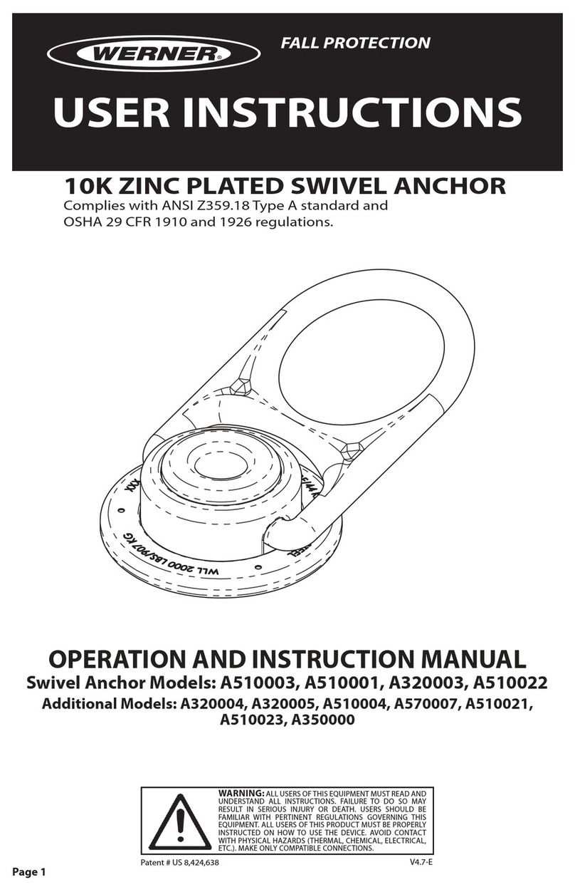
Werner
Werner A519010 User manual
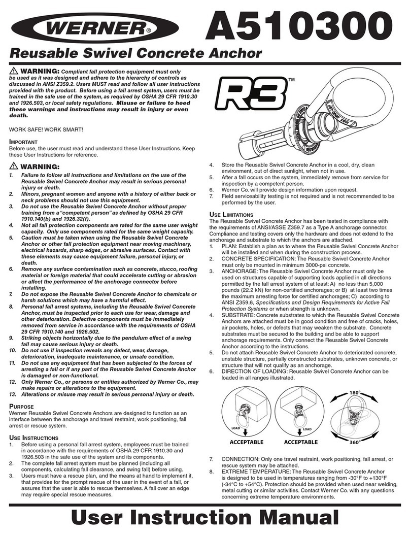
Werner
Werner A550000 User manual

Werner
Werner A550000 User manual

Werner
Werner A330000 Operator's manual

Werner
Werner A410000 Guide

Werner
Werner A410011 User manual