Werner A550000 User manual

INSPECTION AND MAINTAINANCE LOG
Inspection:
user. If severe weather or conditions exist then inspections must be carried out more frequently.
All inspections results must be logged in the space provided above.
Part Number Comments Inspector Name
Date
MODEL NUMBER:
DATE OF MANUFACTURE:
SERIAL NUMBER:
IMPORTANT!!!
ALL PERSONS USING THIS EQUIPMENT MUST READ AND UNDERSTAND ALL INSTRUCTIONS.
FAILURE TO DO SO MAY RESULT IN SERIOUS INJURY OR DEATH. USERS SHOULD BE FAMILIAR
WITH PERTINENT REGULATIONS GOVERNING THIS EQUIPMENT. ALL INDIVIDUALS WHO USE
THIS PRODUCT MUST BE PROPERLY INSTRUCTED ON HOW TO USE THIS DEVICE. DO NOT
ATTEMPT ANY REPAIRS ON THIS EQUIPMENT. CONTACT WERNER CO. FOR FURTHER INSTRUCTION.
Werner Co. / 93 Werner Rd. Greenville, PA 16125 / 1-(888)-523-3371 / www.wernerco.com
I-BEAM SLIDING ANCHOR
ADJUSTABLE FROM 3.5”-14”
Model # A550000
V1.1
proper disposal is required. Beam anchor must be rendered unusable and then properly discarded.
*USER MUST INSPECT EQUIPMENT BEFORE EACH USE*
When inspecting equipment, check for physical deformations, excessive wear, corrosion,
and that all components work properly and safely.
WARNING LABEL LOCATIONS
DONOT REMOVE
StainlessSteel, Aluminum, Zinc Plated Copper,7x19 Aircraft Cable
WARNING!!!
ALLPERSONSUSINGTHIS EQUIPMENT MUST READ AND UNDERSTANDALL INSTRUCTIONS.
FAILURETODOSOMAY RESULT IN SERIOUS INJURYOR DEATH.USERS SHOULD BE FAMILIAR
WITHPERTINENTREGULATIONSGOVERNINGTHIS EQUIPMENT. ALL INDIVIDUALS WHO USE
THISPRODUCTMUSTBE PROPERLYI NSTRUCTEDONHOWTOUSETHIS DEVICE.
Compliance:OSHA 1926.502 & 1910.66 /ANSI Z359.1
CE0321 / EN 795:1996 (+A1:2000) Class B
WARNING: All persons using this equipment must read, understand and
follow all instructions. Failure to do so could result in serious injury or death.
MAX CAPACITY: 310 lbs (140.6 kg) MFG:MM/YYYY
BREAKING STRENGTH: 5000 lbf (22.2 kN)
DO NOT REMOVE
Max Capacity 310-lbs
I-Beam Sliding Anchor
Model: A550000
1-(888)-523-3371
Stainless Steel, Aluminum, Zinc Plated Steel, Bronze
Compliance: OSHA 1926.502 & 1910.66 / ANSI Z359.1 ANSI Z359.7
WARNING!!!
ALL PERSONS USING THIS EQUIPMENT MUST READ AND UNDERSTAND ALL INSTRUCTIONS.
FAILURE TODO SO MAY RESULT IN SERIOUS INJURY OR DEATH. USERS SHOULD BE FAMILIAR
WITH PERTINENT REGULATIONS GOVERNING THIS EQUIPMENT. ALL INDIVIDUALS WHO USE
THIS PRODUCT MUST BE PROPERLY INSTRUCTED ON HOW TO USE THIS DEVICE.
IB14-010
(INSPECT BEFORE USE)
Read This Instruction Manual Carefully Before Using
This Equipment.
USE AND INSTALLATION INSTRUCTIONS
Installation:
1.
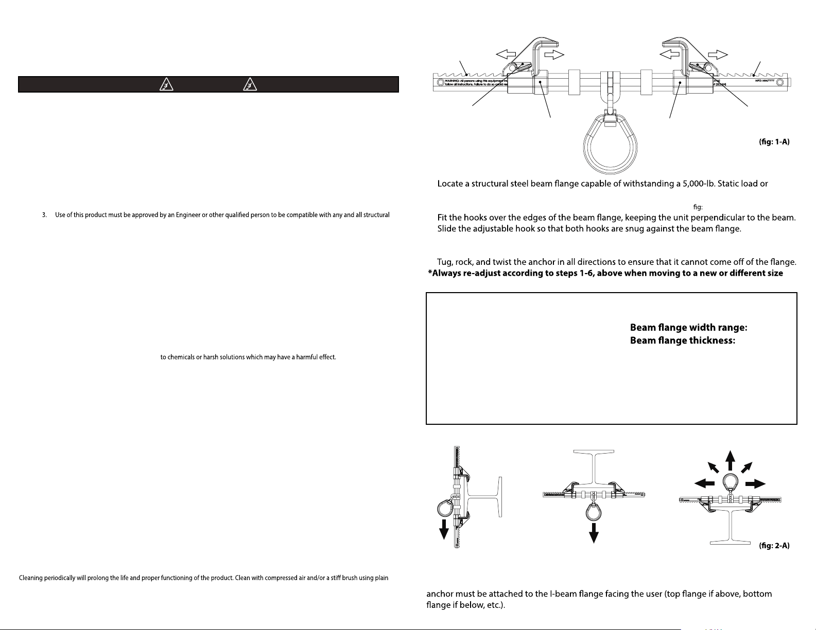
meeting OSHA 1926.502 requirements for a safety factor of two. Avoid swing fall hazards.
2. Push in on the latch handle to allow the adjustable hook to move. (1-A)
3.
4.
5. Pull back on the adjustable hook to ensure the ratchet teeth are fully seated in the nearest
ratchet notches.
6.
beam.
ACCEPTABLE INSTALLATION ORIENTATIONS
Placement at or below a user’s working height requires integration of a compatible ANSI 359.1
shock-absorbing lanyard that does not allow the user to extend more than 6 feet (in any
direction) from the anchorage connector before the shock absorber is activated. The beam
(adjustable directions)
(latch handle)
(adjustable hook)
(notches) (notches)
(latch handle)
(adjustable hook)
Performance:
Static tensile strength: 5000-lbf
(22kN) minimum.
Maximum capacity: one worker with
max weight of 310-lbs when used as
a single point anchorage connector
for personal fall arrest or restraint
Dimensions:
Weight: 3.4-lbs
3.5”-14”
Up to 1.25”
Regulatory compliance:
Meets or exceeds ANSI Z359.1-2007
and OSHA 1926.502
Component Materials:
Cross Bar: aluminum, D-Ring Bracket: stainless steel, Clamps: bronze, D-Ring: zinc
plated steel, Spring: zinc plated steel, Hardware: zinc plated steel
General Safety Information
User Instructions must always be available to the user and are not to be removed except by the user of this equipment. For proper use, see
supervisor, User Instructions, or contact the manufacturer.
Compliant fall protection and emergency rescue systems help prevent serious injury during fall arrest. Users and purchasers of this
equipment must read and understand the User Instructions provided for correct use and care of this product. All users of this equipment
must understand the instructions, operation, limitations and consequences of improper use of this equipment and be properly trained
prior to use per OSHA
29
CFR
1910.66
and
1926.503
or applicable local standards. Misuse or failure to follow warnings and instructions
may result in serious personal injury or death.
Purpose
The
A550000
is an anchorage connector designed to function as an interface between the anchorage and a fall protection, work
positioning, rope access, or rescue system for the purpose of coupling the system to the anchorage. Any references to “anchorage connectors”
in this manual include, and apply to, the
A550000.
Use Instructions
1. Before using a personal fall arrest system, user must be trained in accordance with the requirements of OSHA
29
CFR
1910.66
in the safe use of the system and its components.
2. Use only with compliant personal fall arrest components with any restraint systems.
& operational characteristics of the selected installation location and system to be connected to this anchor. Improper use
may result in serious personal injury or death.
4. The anchorage connector must be inspected prior to each use for wear, damage, and other deterioration and defective
components must be immediately removed from service, in accordance with the requirements of OSHA
29
CFR
1910.66
and
1926.502.
5. The complete fall protection system must be planned (including all components, calculating fall clearance, and swing fall)
before using.
6. A rescue plan, and the means at hand to implement it, must be in place that provides the prompt rescue of users in the
event of a fall, or assures that users are able to rescue themselves.
7. After a fall occurs, anchorage connectors must be removed from service and destroyed immediately.
Use Limitations
1. The
anchorage connector
is designed for single user at one time, per system, with a capacity up to
310
lb (
181
kg) per
use including clothing, tools, etc.
2.
Anchorage connector
may be pulled in any direction shown in FIGURE
2
-A
3.
Anchorage connectors
are designed to be used in temperatures ranging from -40ºF to +130ºF (-40°C to +54°C).
4. Do not expose
anchorage connectors
5. Do not alter or modify this product in anyway.
6. Caution must be taken when using any component of a fall protection, work positioning, rope access, or rescue system near
moving machinery, electrical hazards, sharp edges, or abrasive surfaces, as contact may cause equipment failure, personal
injury, or death.
7. Do not use/install equipment without proper training by a“competent person” as defined by OSHA
29
CFR
1926.32
(f).
8. Do not remove the labeling from this product.
9. Additional requirements and limitations may apply depending on anchorage type and fastening option utilized for
installation Refer to the applicable section in this manual for further details. Improper use may result in serious personal
injury or death.
COMPATIBILITY LIMITATIONS
All Beam Anchors must only be coupled to compatible connectors. OSHA
29
CFR
1926.502
prohibits snaphooks from being engaged to
certain objects unless two requirements are met: it must be a locking type snaphook, and it must be “designed for” making such a
connection. “Designed for” means that the manufacturer of the snaphook specifically designed the snaphook to be used to connect to the
equipment listed. The following connections must be avoided, because they can result in rollout* :
• Direct connection of a snaphook to horizontal lifeline.
•Two (or more) snaphooks connected to one D-ring.
•Two snaphooks connected to each other.
• A snaphook connected back on its integral lanyard.
• A snaphook connected to a webbing loop or webbing lanyard.
• Improper dimensions of the D-ring, rebar, or other connection point in relation to the snaphook dimensions that would allow the
snaphook keeper to be depressed by a turning motion of the snaphook.
*Rollout: A process by which a snaphook or carabiner unintentionally disengages from another connector or object to which it is coupled.
(ANSI Z
359.1-2007
)
MAINTAINANCE, CLEANING AND STORAGE
water or a mild soap and water solution. Do not use any corrosive chemicals that could damage the product. Wipe all surfaces with a clean dry
cloth and hang to dry, or use compressed air. When not in use, store anchorage connectors in a cool, dry, clean environment, out of direct
sunlight and free of corrosive or other degrading elements.
WARNING
Other Werner Safety Equipment manuals

Werner
Werner A410000 Guide

Werner
Werner AUTOCOIL 2 User manual

Werner
Werner A510300 User manual

Werner
Werner A330000 Operator's manual

Werner
Werner MAX PATROL R410008LE User manual

Werner
Werner A510024 User manual

Werner
Werner L242350CA Series User manual

Werner
Werner A510002 Guide

Werner
Werner A550000 User manual

Werner
Werner QUICKCLICK User manual

Werner
Werner KNAACK User manual

Werner
Werner A519010 User manual

Werner
Werner Bantam 6 User manual

Werner
Werner A410400 Guide

Werner
Werner A519000 User manual

Werner
Werner A410011 User manual

Werner
Werner A10030 Series User manual

Werner
Werner UPGEAR L242 Series User manual

Werner
Werner A570000 User manual

Werner
Werner A510010 User manual


