Werner A410011 User manual
User Instructions must always be available to the user and are not to be removed except by the user of this equipment. For proper use, see supervisor, User
Instructions, or contact the manufacturer. Werner Co. can supply additional information upon request.
Compliant fall protection and emergency rescue systems help prevent serious injury during fall arrest. Users and purchasers of this equipment must read and
understand the User Instructions provided for correct use and care of this product. All users of this equipment must understand the instructions, operation,
limitations and consequences of improper use of this equipment and be properly trained prior to use in accordance with applicable standards. All references
to “applicable standards” refer to ANSI, OSHA, state, local, and/or federal standards that apply to approved use. The local competent person must keep these
instructions, make them available to users, and require their use.
Misuse or failure to follow warnings and instructions may result in serious personal injury or death.
PURPOSE
The A410011 is an anchorage connector designed to function as an interface between the anchorage and a fall arrest, work positioning, rope access, or
rescue system for the purpose of coupling the system to the anchorage. Any references to“anchorage connector” in this manual include, and apply to, the
A410011.
USE INSTRUCTIONS
1. A user must be of sound mind and body to properly and safely use this equipment in normal and emergency situations.
2. Before using a personal fall arrest system, user must be trained in accordance with the requirements of applicable standards in the safe use of
the system and its components.
3. Only use with systems that comply with applicable standards. The anchorage must have the strength capable of supporting a static
load, applied in the directions permitted by the system, of at least 5,000-lbf (22kN) in the absence of certication.
4. The user shall be equipped with a means of limiting the maximum dynamic forces exerted on the user during the arrest of a fall to a maximum
of 8 kN (1800-lbf). In the EU these forces must be limited to 6 kN (1350-lbf)
5. Use of this product must be approved by an engineer or other qualied person (as dened by OSHA 29 CFR 1926.32 (m)) to be compatible with
any and all structural & operational characteristics of the selected installation location and system to be connected to this anchorage
connector.
6. The anchorage connector must be inspected prior to each use for wear, damage, and other deterioration. If defective components are
found the anchorage connector must be immediately removed from service in accordance with applicable standards and the manufacturer’s
inspection requirements.
7. The anchorage connector should be positioned in such a way that minimizes the potential for falls and the potential fall distance during use.
The complete fall arrest system must be planned (including all components, calculating fall clearance, and swing fall) before using.
8. A rescue plan, and the means at hand to implement it, must be in place that provides the prompt rescue of users in the event of a fall, or
assures that users are able to rescue themselves.
9. After a fall occurs the anchorage connector must be removed from service and destroyed immediately.
USE LIMITATIONS: This anchorage connector has been tested in compliance with the requirements of ANSI/ASSE Z359.7. Compliance testing covers
only the hardware and does not extend to the anchorage and substrate to which the anchorage connector is attached. The anchorage connector
must not be used outside its limitations, or for any purpose other than that for which it is intended. If this anchorage connector is used dierently
from these instructions, it must be designed, installed, and used under the supervision of an engineer according to ANSI Z359.6 and local building
codes as applicable.
1. The anchorage connector is designed for single user.
2. The anchorage connector may only be loaded as shown in the LOAD DIAGRAM.
3. The anchorage connector is designed to be used in temperatures ranging from -40ºF to +130ºF (-40°C to +54°C).
4. Do not expose the anchorage connector to chemicals or harsh solutions which may have a harmful eect.
5. Do not alter or modify this product in any way.
6. Caution must be taken when using any component of a fall arrest, work positioning, rope access, or rescue system near moving machinery,
electrical hazards, sharp edges, or abrasive surfaces, as contact may cause equipment failure, personal injury, or death.
7. Do not use/install equipment without proper training by a“competent person”as defined by OSHA 29 CFR 1926.32(f).
8. Do not remove the labeling from this product.
9. Additional requirements and limitations may apply depending on anchorage type and fastening option utilized for installation.
All placements must be approved by an engineer or other qualied person.
10. This anchorage connector should not be used as part of a horizontal lifeline system that has not been designed and/or approved to be used
with 5,000-lbf anchorage connectors.
11. The anchorage connector should only be used as intended (see PURPOSE).
12. If attaching the anchorage connector to the support structure by methods other than instructed, the attachment must be certied by
a qualied person to meet the requirements of the system that will connect to the anchorage connector.
COMPATIBILITY LIMITATIONS
Anchorage connector must only be coupled to compatible connectors. OSHA 29 CFR 1926.502 and 1910.140 prohibits snaphooks from being engaged to
certain objects unless two requirements are met: it must be a locking type snaphook, and it must be “designed for” making such a connection. “Designed for”
means that the manufacturer of the snaphook specifically designed the snaphook to be used to connect to the equipment listed. The following connections
must be avoided, because they can result in rollout* when a nonlocking snaphook is used:
• Direct connection of a snaphook to horizontal lifeline.
• Two (or more) snaphooks connected to one D-ring.
• Two snaphooks connected to each other.
• A snaphook connected back on its integral lanyard.
• A snaphook connected to a webbing loop or webbing lanyard.
• Improper dimensions of the D-ring, rebar, or other connection point in relation to the snaphook dimensions that would allow the snaphook
keeper to be depressed by a turning motion of the snaphook.
*Rollout: A process by which a snaphook or carabiner unintentionally disengages from another connector or object to which it is coupled.
MAINTENANCE, CLEANING AND STORAGE
Cleaning periodically will prolong the life and proper functioning of the product. The frequency of cleaning should be determined by inspection and by
severity of the environment. Clean with compressed air and/or a sti brush using plain water or a mild soap and water solution. Do not use any corrosive
chemicals that could damage the product. Wipe all surfaces with a clean, dry cloth and hang to dry, or use compressed air. When not in use, store anchorage
connectors in a cool, dry, clean environment, out of direct sunlight and free of corrosive or other degrading elements.
Read This Instruction Manual Carefully Before Using This Equipment.
Toggle Bolt Anchor
5,000-lbf / 22kN
Model: A410011
Assembled in the USA
V1.1-CPatent #US 8,353,653
WARNING: ALL USERS OF THIS EQUIPMENT MUST READ AND
UNDERSTAND ALL INSTRUCTIONS. FAILURE TO DO SO MAY
RESULT IN SERIOUS INJURY OR DEATH. USERS SHOULD BE
FAMILIAR WITH PERTINENT REGULATIONS GOVERNING THIS
EQUIPMENT. ALL USERS OF THIS PRODUCT MUST BE PROPERLY
INSTRUCTED ON HOW TO USE THE DEVICE. AVOID CONTACT
WITH PHYSICAL HAZARDS (THERMAL, CHEMICAL, ELECTRICAL,
ETC.). MAKE ONLY COMPATIBLE CONNECTIONS.
INSPECTION AND MAINTENANCE LOG
Part Number
MODEL NUMBER:
DATE OF MANUFACTURE:
Comments Inspector Name
Inspection:
Ocial periodic inspection must be made at least annually. The inspection must be
performed by a competent or qualied person other than the user. If severe weather or
conditions exist, then inspections must be carried out more frequently. All inspection
results must be logged in the space provided above.
1. Inspect unit for visible signs of damage or wear that could aect operation. For
example: kinked or frayed cables.
2. Ensure all labeling is axed to the unit.
3. Check that components operate smoothly with no metal burrs.
4. When reusing a previously drilled hole, inspect for debris or wallowing.
5. Record inspection results in the space provided above.
* If inspection reveals any damage that could aect the strength or operation
of the device, inadequate maintenance, or an unsafe condition, proper disposal
is required. The anchorage connector must be rendered unusable and then
properly discarded.
Date
Werner Co.
93 Werner Road
Greenville, PA 16125
1(888) 523-3371 / www.wernerco.com
P/N 124287-01 REV B 4/21
*The user shall be equipped with
a means of limiting the maximum
dynamic forces exerted on the
user during the arrest of a fall to a
maximum of 8 kN (1800-lbf). In the
EU these forces must be limited to
6 kN (1350-lbf).
90º
0º
LOAD DIAGRAM
Ok
Good
Best
Ok
Good
90º
PERFORMANCE:
Minimum Breaking Strength: 5000-lbf (22kN)
Maximum Capacity: One worker when
used as a single point anchorage
connector for personal fall arrest or
restraint system
DIMENSIONS:
Weight: .5-lbs (227g)
Length: 10 inches (254mm)
Diameter 11/16 inch (18mm)
REGULATORY COMPLIANCE:
OSHA 29 CFR 1926.502, OSHA 29
CFR1910.140, ANSI Z359.18 Type A
COMPONENT MATERIALS:
Aluminum: Hole Plug, Trigger
Aircraft Cable: Main Cable, Activator Wire
Stainless Steel: Toggle Bar, Termination
Zinc Plated Steel: Spring, D-Ring
FEP: Tubing
May be used as an anchor point for a leading edge
restraint system. See optional anchor points below
for example. The use of two anchors is not required for
leading edge restraint systems unless otherwise
specied by the manufacturer.
WORK SURFACE
OPTIONAL
(ANCHOR POINTS)
WORK SURFACE
(ANCHOR POINT)
Installation location
to be approved by a
qualied person.
MINIMUM CLEARANCE 2 feet (.6m)
DECK/FLOOR/GROUND LEVEL
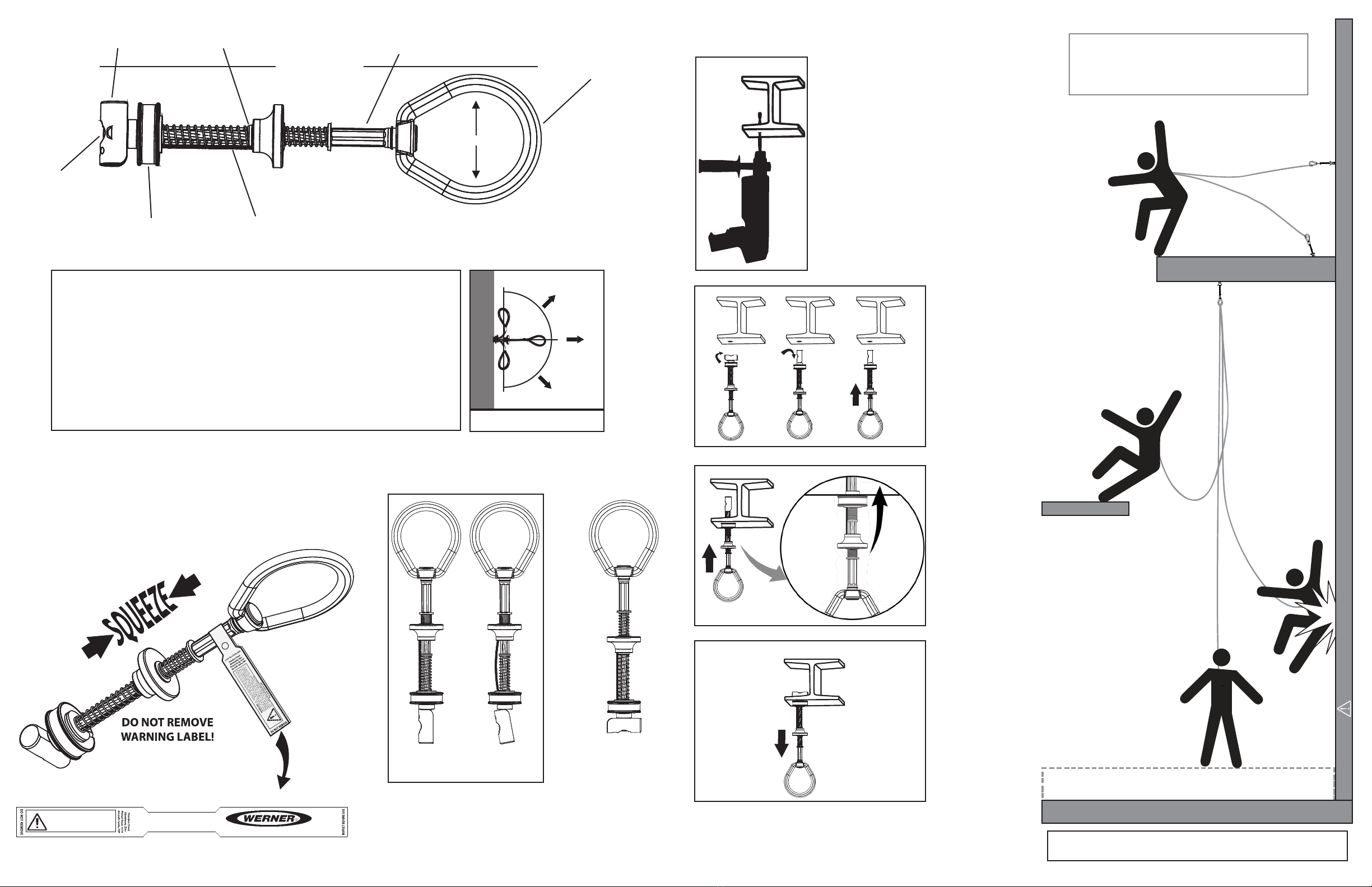
WARNING!!! SWING FALLS CAN OCCUR WHEN THE WORKER IS NOT DIRECTLY UNDER ANCHOR POINT.
All products subjected to fall arresting forces should be removed
from service immediately!
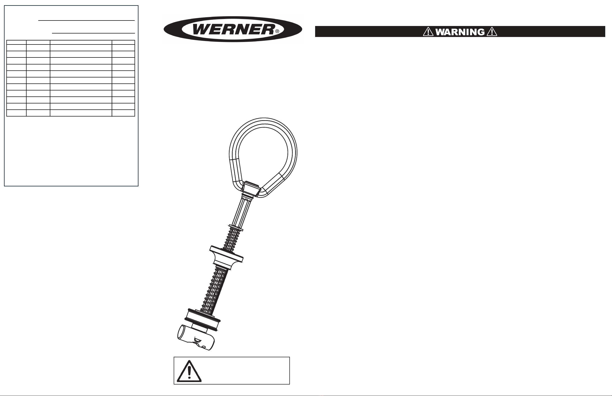
Hole Plug Trigger Wire
Ball Shank
10 inches (254mm)
Trigger Stop Washer Swage Termination
D-Ring
11/16 inch Toggle Bar
WARNING! Location of installation of the toggle anchor must be
approved by an engineer or other qualied person to be compatible
with any and all structural & operational characteristics of the
selected installation location.
INSTALLATION INSTRUCTIONS:
For Steel Applications Only.
Drill a 11/16 inch (18mm) hole in the
steel ange. Steel thickness must be
between .25 inch (6.4mm) and 1.25 inches
(31.75mm). Hole should be no closer than
1.5 inches (38mm) to any edge.
*Always inspect the hole carefully when
reusing a previously drilled hole.
1.
2.
3.
4.
Push anchorage
connector into
drilled hole.
Pull on anchor
loop and ensure
toggle bar is fully
seated in locked
position as seen in
the TOGGLE
POSITION
DIAGRAM. The
hole plug should
be fully seated in
drilled hole.
Rotate toggle bar
into open position
and insert into
hole.
OPEN
POSITION
KINKED
CABLE
LOCKED
POSITION
OPEN
POSITION
KINKED
CABLE
LOCKED
POSITION
TOGGLE POSITION DIAGRAM
The Trigger and Trigger-wire may be used as a means of
determining toggle position when view of toggle bar is ob-
structed by the anchorage. Trigger should be in contact with
the trigger stop washer AND Trigger-wire should be straight
in-line with the rest of the device to ensure toggle bar is in
locked position.
Compliance: OSHA 29 CFR 1926.502, OSHA 29 CFR 1910.140,
ANSI Z359.18 Type A
Toggle Bolt Anchor
Model: A410011
Batch# XXXX
MFD: MM/YYYY
1(888) 523-3371
Pat # US 8,353,653
WARNING:
ALL USERS OF THIS EQUIPMENT MUST READ AND
UNDERSTAND ALL INSTRUCTIONS. FAILURE TO DO SO MAY
RESULT IN SERIOUS INJURY OR DEATH. USERS SHOULD BE
FAMILIAR WITH PERTINENT REGULATIONS GOVERNING THIS
EQUIPMENT. ALL USERS OF THIS PRODUCT MUST BE PROPERLY
INSTRUCTED ON HOW TO USE THE DEVICE. AVOID CONTACT
WITH PHYSICAL HAZARDS (THERMAL, CHEMICAL, ELECTRICAL,
ETC.). MAKE ONLY COMPATIBLE CONNECTIONS.
5,000-lbf (22kN) MBS
P/N 109811-14 REV F 4/21
Compliance: OSHA 29 CFR 1926.502, OSHA 29 CFR 1910.140,
ANSI Z359.18 TypeA
Toggle Bolt Anchor
Model: A410011
Batch# XXXX
MFD: MM/YYYY
1(888) 523-3371
Pat # US 8,353,653
WARNING:
ALL USERS OFTHIS EQUIPMENT MUST READ AND
UNDERSTAND ALL INSTRUCTIONS. FAILURE TO DO SO MAY
RESULT IN SERIOUS INJURY OR DEATH. USERS SHOULD BE
FAMILIAR WITH PERTINENT REGULATIONS GOVERNING THIS
EQUIPMENT. ALL USERS OFTHIS PRODUC T MUST BE PROPERLY
INSTRUCTED ON HOW TO USE THE DEVICE. AVOID CONTACT
WITH PHYSICAL HAZARDS (THERMAL, CHEMICAL, ELECTRICAL,
ETC.). MAKE ONLYCOMPATIBLE CONNECTIONS.
5,000-lbf (22kN) MBS
P/N 109811-14 REV F 4/21
UNSAFE
2 inches
Other Werner Safety Equipment manuals

Werner
Werner A410000 Guide

Werner
Werner A550000 User manual

Werner
Werner A519010 User manual

Werner
Werner A114002 Guide

Werner
Werner A519000 User manual

Werner
Werner Bantam 6 User manual

Werner
Werner A510010 User manual

Werner
Werner A510003 User manual

Werner
Werner QUICKCLICK User manual

Werner
Werner A550000 User manual

Werner
Werner MAX PATROL R410008LE User manual

Werner
Werner A570000 User manual

Werner
Werner A410400 Guide

Werner
Werner A320013 Guide

Werner
Werner UPGEAR L242 Series User manual

Werner
Werner MAX PATROL R410020 User manual

Werner
Werner KNAACK User manual

Werner
Werner A10030 Series User manual

Werner
Werner A510002 Guide

Werner
Werner A510024 User manual


