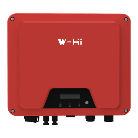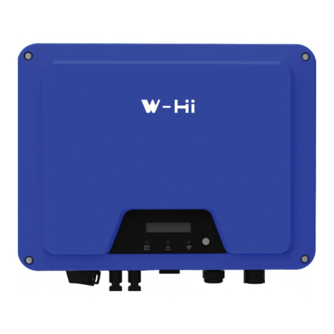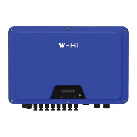
φ43-51φ34-43φ26-34φ21-26
3.3AC Wire Assembly and ConnectionDanger to Life due to High Voltages in the InverterBefore connecting any electrical wires and components, please ensure the DC switch & AC circuit breaker are switched OFF and cannot be reactivated.DANGER DC Wire Assembly and ConnectionMeeting the following requirements is mandatory. All warranty rights will otherwise be invalid.3.3.1 Maximum open voltage of each string is less than 1100V.3.3.2 Maximum short circuit current of each PV input is less than inverter allowable limit.3.3.3 The string is well insulated to ground in all cases.3.3.4 Make sure that the DC connectors have the correct polarity.3.3.5 If the PV connectors are not assembled properly and locked into place, arc or overheat may be induced.3.4Step 1Step 2Step 3Please check if1. The inverter and mounting bracket have been correctly installed. 2. The inverter’s exposed metal surface has a ground connection. 3. The resistance between PV arrays and ground is greater than 1Mohm. 4. For any unused DC terminals, there are DC connectors inserted to the terminal and sealed with waterproof caps. 5. The grid voltage at the point of connection of the inverter is within the permitted range. 6. The AC circuit breaker must be correctly rated and wired. 7. The cable communication connectors have been correctly wired and tightened.StartupSwitch on the DC switch after finishing the above checks, then switch on the AC circuit breaker. When there is sufficient DC power applied and the grid conditions are met, the inverter will start to operate automatically. Commissioning4.RS485/Smart Meter and DRED ConnectionNOTICE For AS/NZS 4777, DRM0 is supported.Make sure the cover and the communication cable gland has been mounted properly and adequatelyStep 1Step 2Wi-Fi/GPRS Connection The stick is included in the scope of delivery as an option. 3.4.1 Tighten the stick into the COM1 port.Make sure the stick is securely connected.3.4.2 For the connection and configuration of the Wi-Fi stick please refer to <Wi-Fi stick User manual> .3.5Step 3Step 4+86 0512-80712166Service Contact: service@hypontech.comwww.hypontech.com +86 0512-80712382www.hypontech.comAddress: No.588 Wutaishan Road, SND, Suzhou , ChinaGUIDEWAY2314Use the right sealing ring according to the diameter of the cable1234Press the cable into the appropriate terminal.Use a screwdriver to lock the cable to the corresponding position and tighten the screws on the box following the indicated sequence (1~4)Assemble the box, threaded sleeve and swivel nut togetherStep 1Step 2Step 3Step 4Step 5Step 6clickclick117mm7mm
PV1-F/UL-ZKLA/USE2PV1-F/UL-ZKLA/USE2
Assemble the connectors2.6-2.9 N·mPositiveNegativeAssemble the cable endsD4Positive terminalNegative terminalCrimp pliers to cable endsNote: Don't crimp this part!Assemble the cable endsMC4Positive terminalNegative terminal24-6mm216mm26mm
Approx. 10 mm
RS485 B1RS485 A2RS485 B2RS485 A1PIN1PIN2PIN3PIN4RS485 FOR COM2Meter or DRED FOR COM3COMLOAD/0RS485 ARS485 BREF GEN/0PIN1PIN2PIN3PIN4
Pull out the plastic rivet and remove the plastic sheetThe download of the current warranty conditions is available on www.western.itWESTERN CO. S.r.l. via Pasubio 1 / 3– 63074 San Benedetto del Tronto (AP) Italy Tel. (+39) 0735 751248 Fax (+39) 0735 751254 VAT number: 01192450441 For more information, please download the user manual and other technical documents at www.western.it3.6

