Western Wmarine10 User manual

Wmarine10
SOLAR MPPT CHARGE CONTROLLER
Manuale utente
User manual
Manuel de l’utilisateur
Manual del usuario
Benutzerhandbuch
IT
DE
ES
FR
EN


WMarine10
Manuale utente
IT
REV 1.4 19-01-2018
1
REGOLATORE DI CARICA BATTERIA
DA MODULO FOTOVOLTAICO
WMarine10
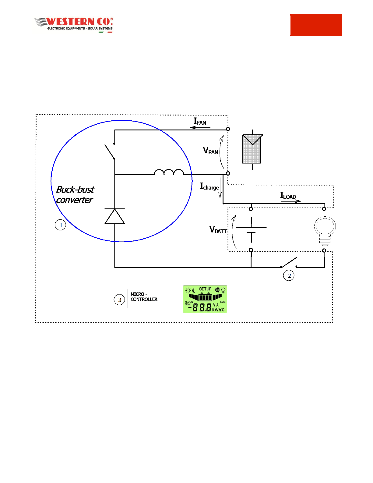
Il regolatore di carica WMarine10 implementa un circuito di carica di tipo buck-
boost con controllo del punto di massima potenza del modulo PV (MPPT). La
principale differenza tra questo regolatore e altre tipologie come ad esempio il
regolatore WRM15 (che implementano invece un circuito di tipo buck) è che il
WMarine10 è in grado di far lavorare il modulo PV ad una tensione sia
superiore che inferiore a quella della batteria e ciò consente ad esempio di
impiegare un modulo PV con tensione open circuit di 10V per la ricarica di
batterie sia a 12V che a 24V. La tensione del modulo PV durante il
funzionamento del circuito MPPT va da 5V a 30V sia con batterie a 12V che a
24V.
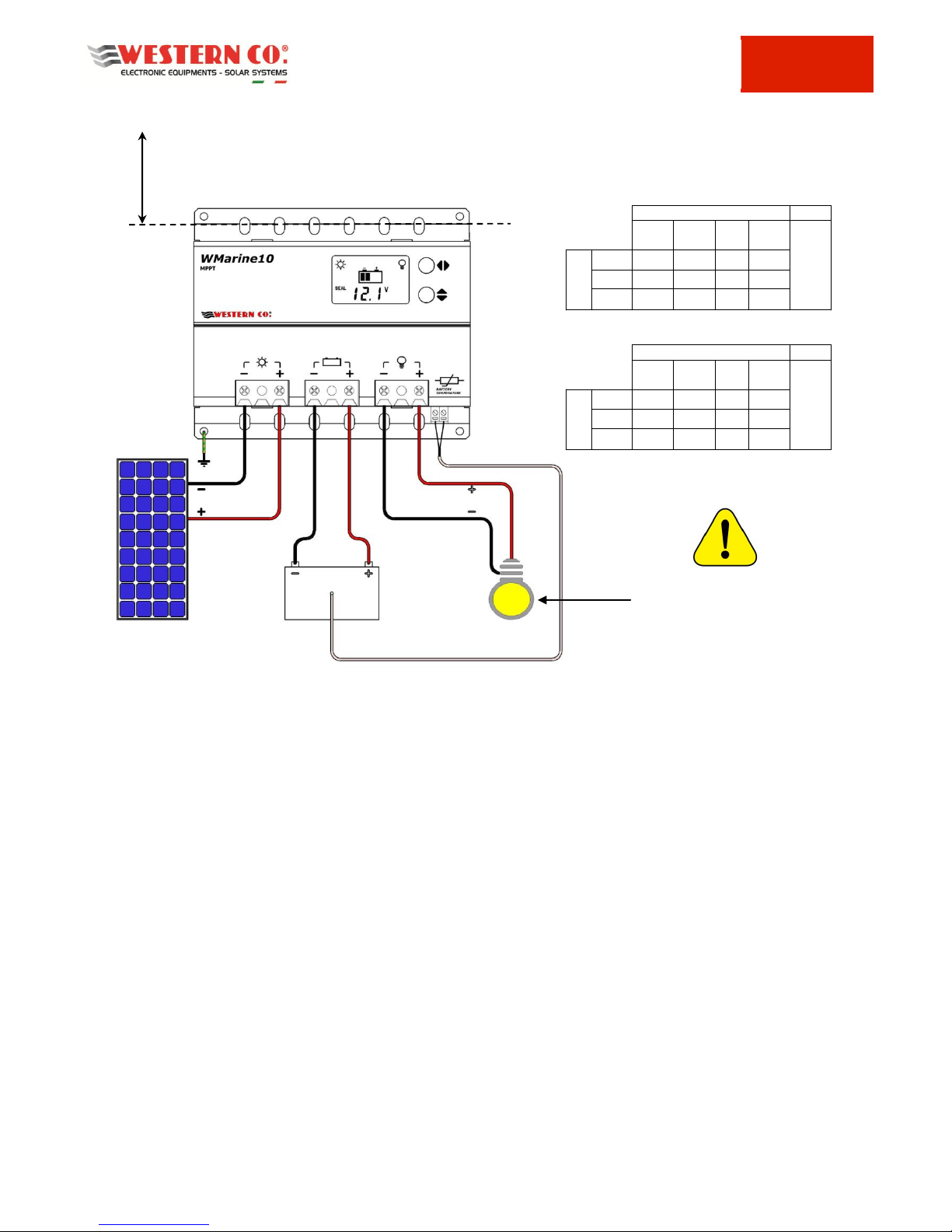
Il WMarine10 è una soluzione completa per la realizzazione di impianti
fotovoltaici ad isola, per alimentare sistemi di segnaletica stradale, sistemi di
illuminazione, per alimentare piccole utenza a bassa tensione e per la carica di
batterie all’interno dei camper e imbarcazioni. I vari programmi di gestione
carico selezionabili rendono il WMarine10 la soluzione completa in molte
applicazioni; ad esempio per alimentare telecamere che debbono funzionare
solo di giorno, oppure per alimentare lampeggiatori o segnalazioni stradali che
debbono funzionare solo di notte o per alimentare sistemi di illuminazione che
debbono funzionare per un determinato numero di ore per notte. Il
WMarine10 rileva lo stato giorno/notte in base alla tensione di pannello,
quindi non è necessario collegare ulteriori sensori al regolatore. Un ampio
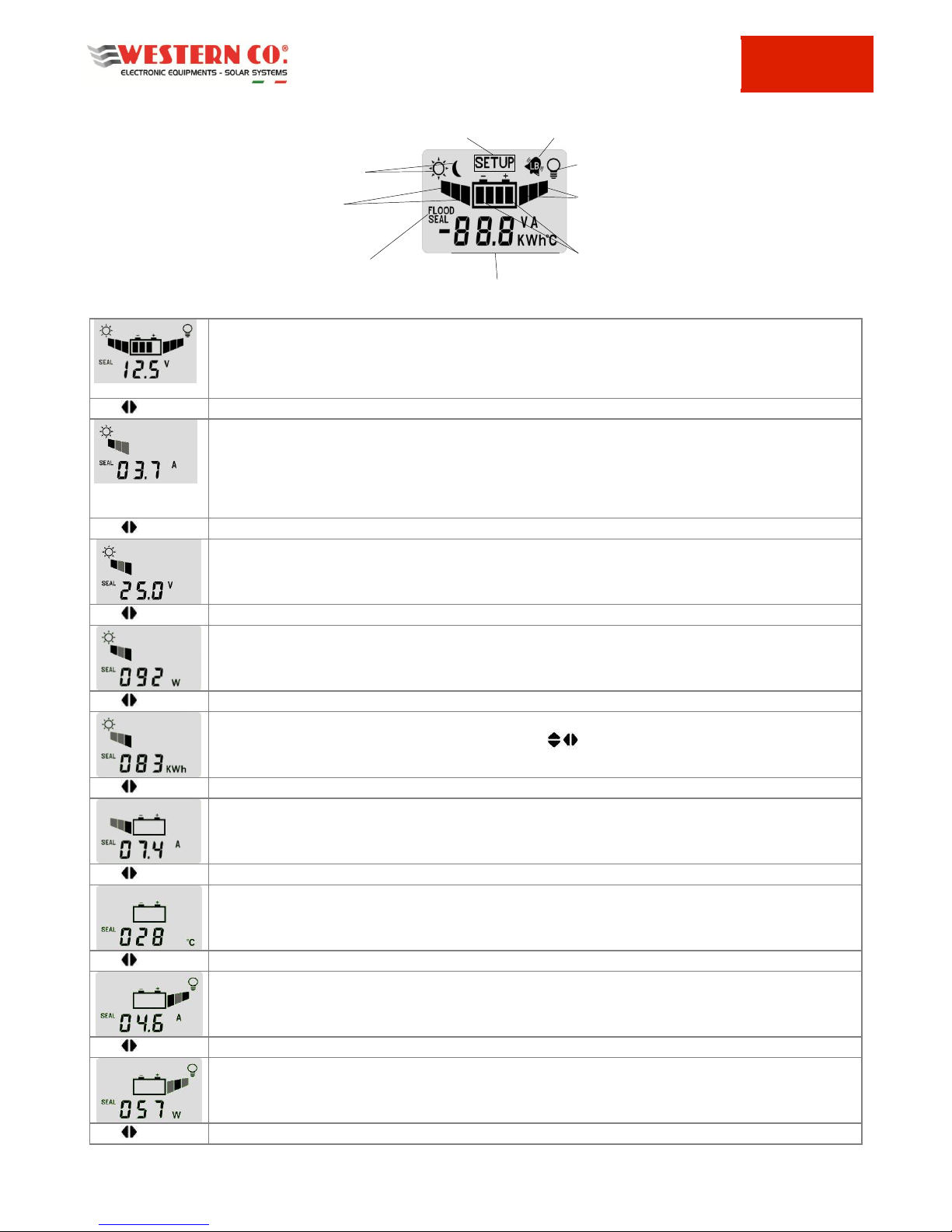
display visualizza lo stato di funzionamento del regolatore sia attraverso icone
semplici ed intuitive sia visualizzando il valore della corrente di carica, la
tensione di batteria, l’energia prodotta dal modulo PV, la corrente del carico e
l’energia consumata dal carico.
Carica MPPT con circuito buck-boost
Massima potenza di pannello 120W per
batteria a 12V e 220W per batteria a
24V
Diodo di blocco integrato
Per batterie ermetiche, GEL ed acido
libero e Batterie agli ioni di litio (da
Rev 1.2)
Tensione di carica compensata in
temperatura
Auto-detect tensione di batteria 12V /
24V
18 programmi per gestione carico
LCD 48 simboli per interfaccia utente
Protezione batteria scarica
Protezione sovra-temperatura
Protezione inversione polarità batteria
Protezione sovraccarico su uscita load
Contenitore in metallico IP20

WMarine10
Manuale utente
IT
2
Descrizione generale
WMarine10 è un regolatore di carica da moduli fotovoltaici per batterie elettrochimiche al piombo di tipo ermetico
(SEAL) o ad acido libero (FLOOD). Dalla Rev 1.2 è stato introdotto un programma per la carica di batterie agli ioni di litio
del tipo che hanno integrato il BMS (Battery Management System); Consigliamo di contattare la Western CO. per la
scelta della batteria agli ioni di litio da collegare al WMarine10. E’ assolutamente vietato collegare al WMarine10
batterie agli ioni di litio che non hanno un BMS integrato; infatti il BMS protegge la batteria da condizioni di
funzionamento anomalo che potrebbero portare all’incendio della batteria stessa.
In fig. 1 è riportato uno schema di principio del WMarine10.
Fig. 1 Schema di principio
1- Circuito di ricarica: adatta la VPAN e la IPAN (rispettivamente tensione e corrente del modulo fotovoltaico) in modo da
ricercare la condizione in cui la potenza erogata dal modulo PV è massima, realizzando quello che nella letteratura
tecnica è indicato con la sigla MPPT (Maximum Power Point Tracking). Inoltre gestisce la carica della batteria
riducendo la corrente erogata verso la batteria nelle condizioni in cui la tensione VBATT supera la sua tensione di carica
(Vch).
2- Circuito per il controllo del carico: accende/spegne il carico secondo il programma impostato dall’utente e provvede
al distacco del carico in caso di batteria scarica o sovraccarico o cortocircuito sul carico.
3- Microprocessore: controlla l’intero circuito, misura le correnti e tensioni del modulo della batteria e del carico e le
visualizza sul display.

WMarine10
Manuale utente
IT
3
Schema di collegamento
MODULO
PV
BATTERIA
CARICO
SENSORE DI TEMPERATURA BATTERIA
Minima distanza
>
10 Cm
Sezioni coppie di filo in rame raccomandate che garantiscono
caduta di tensione massima pari a 1.5% della tensione nominale
della batteria.
Tensione nominale batteria 12V
Sezione filo
2.5
mm2
4
mm2
6
mm2
10
mm2
Max. distanza
coppia fili [m]
Corrente
5 A
2.6
4.2
6.3
10.4
10 A
1.3
2.1
3.1
5.2
20 A
0.9
1.4
2.1
3.5
Tensione nominale batteria 24V
Sezione filo
2.5
mm2
4
mm2
6
mm2
10
mm2
Max. distanza
coppia fili [m]
Corrente
5 A
5.2
8.4
12.5
20.9
10 A
2.6
4.2
6.3
10.4
20 A
1.7
2.8
4.2
7.0
Fig. 2 Schema di collegamento
1) Installare il WMarine10 in un luogo asciutto ed adeguatamente arieggiato, fissato su di una superficie non
infiammabile e posizionato in modo da lasciare uno spazio privo di ostacoli di almeno 10Cm nell’intorno del dispositivo
che ne permette il raffreddamento per convezione naturale dell’aria.
2) Collegare: il carico, la sonda per misura temperatura batteria (in dotazione), modulo PV e per ultimo la batteria come
nello schema fig. 2. Alla connessione della batteria il regolatore si accende e inizia a funzionare. Impiegare sezioni di
cavo appropriati come indicato nella tabella di fig. 2.
3) Il WMarine10 riconosce automaticamente la tensione nominale di batteria (12V o 24V) e adegua di conseguenza le
sue soglie di funzionamento. L’utente deve però configurare il tipo di batteria in uso per adeguare la corretta tensione di
ricarica (Vch ). Si deve impostare la configurazione SEAL se si usano batterie ermetiche VRLA o di tipo GEL, si deve
impostare la configurazione FLOOD se si usano batterie ad acido libero, mentre nel caso di impiego di batterie agli ioni
di litio è necessario impostare anche l’esatta tensione di fine carica della batteria (vedi fig. 4 pagina impostazioni
programma di carica).
4) Impostare il programma di gestione del carico adeguato alla propria applicazione (fig. 4).
Collaudo dell’impianto
Appena realizzati i collegamenti come in fig. 2 è necessario procedere al collaudo del sistema.
1) Con il modulo PV esposto al sole, verificare che il WMarine10 ricarica la batteria andando a leggere la corrente di
ricarica IPAN e IBAT (vedi fig. 3).
2) Per verificare se la sonda di temperatura della batteria è stata collegata correttamente verificare su LCD che alla
pagina temperatura di batteria sia visualizzato un valore di temperatura attendibile (fig. 3).
3) Verificare la corretta accensione del carico. Se il carico è acceso solo di notte è possibile simulare la notte scollegando
temporaneamente uno dei fili del modulo PV. Con il carico acceso, verificare la corrente da questo assorbita leggendo
nell’apposita pagina dell’LCD (fig. 3).
ATTENZIONE!
Non collegare all’uscita
carichi che assorbono più
di 15A come gli inverter.

WMarine10
Manuale utente
IT
4
Visualizzazioni
Pagina principale.
Visualizza la tensione di batteria (VBAT), il programma di ricarica attualmente selezionato (SEAL
oppure FLOOD), lo stato giorno/notte rilevato dal modulo PV e l’icona del carico, se accesa, indica
che il carico è alimentato.
Tasto
visualizza la corrente (IPAN) del modulo PV. Ricordiamo che la corrente erogata dal modulo PV
dipende dallo stato di soleggiamento dello stesso e dallo stato di carica della batteria. Con la
batteria carica (Vbatt>14,4V @12V o Vbatt>28,8V @24V) anche con un buon soleggiamento del
modulo si hanno correnti di ricarica basse in quanto è il regolatore che limita tale corrente per
evitare sovraccarico della batteria.
Tasto
Tensione del modulo PV (VPAN).
Tasto
Visualizza la potenza in watt attualmente erogata dal modulo PV.
Tasto
Visualizza il contatore dell’energia erogata dal pannello in KWh. E’ possibile azzerare questa
misura premendo contemporaneamente i pulsanti per 2 secondi.
Tasto
Visualizza la corrente di carica in batteria (IBAT).
Tasto
Visualizza la temperatura della batteria attualmente misurata dalla sonda di temperatura
collegata al WMarine10.
Tasto
Visualizza la corrente attualmente erogata al carico; anche se in questa schermata compare
accesa l’icona dal carico non è detto che questo sia effettivamente alimentato, infatti il carico è
controllato secondo il programma di gestione carico attualmente impostato .
Tasto
Visualizza la potenza attualmente erogata al carico in watt.
Tasto
Visualizza le misure interne
Stato giorno/notte
Visualizzato nelle sole schermate di
configurazione
Segnalazione batteria scarica
Accensione carico
Indica quale programma di
ricarica è attualmente impostato
Livello di tensione nella batteria
Indicazione assorbimento
corrente sul carico
Indicazione assorbimento
corrente dal modulo PV

WMarine10
Manuale utente
IT
5
E’ visualizzato il contatore dell’energia in KWh consumati dal carico. E’ possibile azzerare questo
contatore premendo contemporaneamente i pulsanti per 2 secondi.
Tasto
Alla pressione del tasto si ritorna alla pagina principale.
Fig. 3 Pagine visualizzazione misure
Configurazione del sistema
Si accede alle pagine di configurazione del WMarine10 mantenendo premuti contemporaneamente per almeno 2
secondi i tasti .
Pagina configurazione programma di carica
….
Imposta la tensione di carica per la batteria.
SEAL deve essere impostato per batteria Pb ermetiche VRLA o GEL (*).
FOOD deve essere impostato per batteria Pb a vaso aperto (*).
Li deve essere impostato per la carica di batterie al Li. Oltre che ad attivare il programma Li si
deve anche impostare la tensione di fine carica in accordo con le indicazioni del costruttore
della batteria agli ioni di litio. Il WMarine10 permette di impostare la tensione di carica Li
nell’intervallo 14.0V – 14.7V per sistemi a 12V,
28.0V –29.4V per sistemi a 24V.
Per scegliere il corretto valore di tensione di carica per batterie Li è necessario consultare il
manuale della batteria selezionata.
Quando attivo il programma Li la tensione di fine carica non viene compensata in
temperatura e viene imposta al valore selezionato per ogni valore di temperatura letto dal
WMarine10.
*Le tensioni di carica relative a ciascuno dei programmi sono indicate nelle successive fig. 6/8
e vanno scelti in accordo con le indicazioni del costruttore della batteria.
cambio pagina
Pagina Configurazione tensione di Low Battery
Imposta la tensione di intervento della protezione di Low battery (distacco del carico in caso
di batteria scarica). Alla pressione del tasto si modifica l’impostazione da 10.8V a 12.2V per
sistemi a 12V e da 21.6V a 24.4V per sistemi a 24V.
cambio pagina
Pagina Configurazione tensione di uscita da Low Battery
Imposta la tensione di uscita della protezione di Low battery. Alla pressione del tasto si
modifica l’impostazione da 12.4V a 13.8V per sistemi a 12V e da 24.8V a 27.6V per sistemi a
24V.
cambio pagina
Pagina Configurazione programma gestione carico
…
carico sempre acceso
sia di giorno sia di
notte.
carico acceso
solo di giorno.
carico acceso solo
di notte.
carico acceso di
notte per 1 ora.
carico acceso di notte per
16 ore.
cambio pagina
Tensione rivelazione giorno
Il WMarine10 rileva che è giorno quando la tensione del modulo PV (VPAN) è maggiore della
soglia VDAY, invece rileva che è notte quando la VPAN è minore della soglia VNIGHT. E’ possibile
modificare la soglia VDAY , mentre La soglia VNIGHT = VDAY –0.8V
cambio pagina

WMarine10
Manuale utente
IT
6
Tensione float
E’ possibile modificare la tensione di carica della fase float (VFlt a 25°C). Quando la tensione
di batteria è pari alla tensione di fine carica (Vch) per un tempo pari a TAbsorpion
(configurabile) si entra nella fase float. La VFlt è compensata in temperatura (-24mV/°C a 12V e -
48mV/°C a 24V).
cambio pagina
Tempo di Absorption
E’ possibile modificare il tempo TAbsorption; tempo in ore in cui la batteria può rimanere
alla tensione VCh prima di arrivare alla tensione float.
cambio pagina
Pagina visualizzazione versione software
Visualizza la versione software in uso su WMarine10.
Questo manuale è riferito alla versione software 1.2
Si ritorna nella pagina configurazione programma di ricarica
Fig. 4 Pagine impostazioni
Una volta modificate le impostazioni del WMarine10 queste diventano operative solo dopo essere usciti dalla pagine di
configurazione mantenendo premuti contemporaneamente per almeno 2 secondi i tasti .
Codici di errore
All’intervento delle protezioni interne del WMarine10 compaiono dei codici di errore come riportato di seguito.
Tabella codice errore
Il simbolo low battery lampeggiante
indica che è intervenuta la protezione
di batteria scarica e quindi per
preservare la vita della batteria è stato
disconnesso il carico. Questa
protezione interviene quando la
tensione di batteria scende sotto la
soglia VLB impostabile dall’utente (fig.
4). Il WMarine10 esce da questa
protezione quando la batteria sarà
ricaricata dal modulo PV alla tensione
VOUT-LB configurabile.
Intervenuta protezione di sovraccarico. La
corrente del carico ha superato il limite
massimo consentito per il WMarine10 (Iload
nella tabella caratteristiche elettriche) e il
regolatore ha distaccato il carico per
prevenire rotture interne. Nel caso
intervenga questa segnalazione è necessario
verificare se la corrente assorbita dal carico è
inferiore al limite consentito. Dopo 1 minuto
il WMarine10 tenta di alimentare
nuovamente il carico e esce da questo stato
se è sta eliminata la causa che ha generato il
sovraccarico.
E’ stata connessa la batteria con
polarità invertite. Rivedere il
collegamento elettrico della batteria.
Interviene questa segnalazione quando la
tensione di batteria è inferiore a 9.0V. In
queste condizioni è disabilitata la ricarica.
Interviene quando la temperatura
interna del WMarine10 supera gli 80°C
e disattiva la carica. Si esce
automaticamente da questa
protezione quando la temperatura
interna scende al di sotto della soglia
di 50°C. (nota la temperatura interna
al regolatore non è visualizzata
nell’LCD). Qualora intervenga spesso
questa protezione consigliamo di
alloggiare il regolatore in un luogo più
fresco.
Fig. 5 Tabella codici errore

WMarine10
Manuale utente
IT
7
Tensione fine carica in funzione della temperatura sistema a
12V
13,5
14,0
14,5
15,0
15,5
16,0
-10
-5
0
5
10
15
20
25
30
35
40
45
50
55
60
Temperatura °C
Tensione fina carica Volt
SEAL
FLOOD
Tensione fine carica in funzione della temperatura sistema a 24V
27,0
27,5
28,0
28,5
29,0
29,5
30,0
30,5
31,0
31,5
32,0
-10
-5
0
5
10
15
20
25
30
35
40
45
50
55
60
Temperatura °C
Tensione fina carica Volt
SEAL
FLOOD
Fig. 6 Curva di compensazione della tensione di ricarica Vch in funzione della temperatura di batteria
Caratteristiche Elettriche
Tensione nominale batteria
12V
Tensione nominale batteria
24V
Min
Tip
Max
Min
Tip
Max
Tensione di batteria
Vbatt
10V
16V
20V
32V
Tensione di pannello a circuito aperto
Vpan
5V
-
40V
5V
-
40V
Massima potenza di pannello
Pmax
-
-
120W
-
-
220W
Tensione uscita carico
Vload
-
Tensione di
batteria
-
-
Tensione di
batteria
-
Corrente del carico
Iload
-
-
15A
-
-
15A
Tensione di carica a 25°C programma SEAL
(default)
Vch
14.4V
28.8V
Tensione di carica a 25°C programma FLOOD
Vch
14.8V
29.6V
Tensione di carica a 25°C programma Li(*)
Vch
14.0V
-
14.7V
28.0V
-
29.4V
Compensazione della Vch funzione della
temperatura di batteria (Tbatt)
Vtadj
-
-24mV/°C
-
-
-48mV/°C
-
Tensione di low battery (impostabile)
Vlb
10.8V
11.4V
(default)
12.2V
21.6V
22.8V
(default)
24.4V
Tensione uscita low battery (impostabile)
Vout_lb
12.4V
13.8V
(default)
13.8V
24.8V
27.6V
(default)
27.6V
Tensione rilevazione giorno (impostabile)
Vday
1.9V
4.4V
(default)
9.6V
1.9V
4.4V
(default)
9.6V
Tensione rilevazione notte: Vnight = Vday –
1.3V
Vnight
0.6V
-
8.3V
0.6V
-
8.3V
Auto consumo
Isleep
12.7Ma
(Vbat 14,0V)
17,7mA
(Vbat 28,0V)
Temperatura di esercizio
Tamb
-10°C
40°C
-10°C
40°C
Potenza dissipata
Pdiss
20 W
29 W
Sezione ai morsetti
1mm2
10mm2
1mm2
10mm2
Grado di protezione
IP20
IP20
Peso
-
515 g
-
-
515 g
-
Fig. 7 Tabella caratteristiche elettriche
(*)Quando impostato programma Li la tensione di carica non varia con la temperatura misurata sulla batteria.

WMarine10
Manuale utente
IT
8
Dimensioni
Fig. 8 Dimensioni
Garanzia di legge
Western CO. Srl garantisce la buona qualità e la buona costruzione dei Prodotti obbligandosi, durante il periodo di
garanzia di 5 (cinque) anni, a riparare o sostituire a sua sola discrezione, gratuitamente, quelle parti che, per cattiva
qualità del materiale o per difetto di lavorazione si dimostrassero difettose.
Il prodotto difettoso dovrà essere rispedito alla Western CO. Srl o a società delegata dalla Western CO. Srl a fare
assistenza sul prodotto, a spese del cliente, assieme ad una copia della fattura di vendita, sia per la riparazione che la
sostituzione garantita. I costi di re-installazione del materiale saranno a carico del cliente.
La Western CO. Srl sosterrà le spese di re spedizione del prodotto riparato o sostituito.
La garanzia non copre i Prodotti che, in base a nostra discrezione, risultino difettosi a causa di naturale logoramento,
che presentino guasti causati da imperizia o negligenza del cliente, da imperfetta installazione, da manomissioni o
interventi diversi dalle istruzioni da noi fornite. La garanzia decade altresì in caso di danni derivanti da:
- trasporto e/o cattiva conservazione del prodotto.
- causa di forza maggiore o eventi catastrofici (gelo per temperature inferiori a -20°C, incendio, inondazioni, fulmini, atti
vandalici, ecc…).
Tutte le sopraccitate garanzie sono il solo ed esclusivo accordo che soprassiede ogni altra proposta o accordo verbale o
scritto e ogni altra comunicazione fatta tra il produttore e l’acquirente in rispetto a quanto sopra.
Per qualsiasi controversia il Foro competente è Ascoli Piceno.
Smaltimento dei rifiuti
La Western CO. in qualità di produttore del dispositivo elettrico descritto nel presente manuale, ed in
conformità al D.L 25/07/05 n 151, informa l’acquirente che questo prodotto, una volta dismesso,
deve essere consegnato ad un centro di raccolta autorizzato oppure, in caso di acquisto di
apparecchiatura equivalente può essere riconsegnato a titolo gratuito al distributore della
apparecchiatura nuova.Le sanzioni per chi abusivamente si libera di un rifiuto elettronico saranno
applicate dalle singole amministrazioni comunali.
WESTERN CO. Srl
Via Pasubio, 1
63074 San Benedetto del Tronto (AP)
tel: (+39) 0735 751248 fax: (+39) 0735 751254
e-mail: info@western.it
web: www.western.it

WMarine10
User manual
EN
REV 1.4 19-01-2018
1
PHOTOVOLTAIC CHARGE CONTROLLER
WMarine10
WMarine10 has got a buck-boost charge circuit with control of the maximum
power point of the PV module (MPPT). The main difference between this
controller and other types with buck circuit (as for instance WRM15) is that
WMarine10 is able to allow the working of the PV module at a voltage than can
be either higher or lower than that of battery; this allows, for example, to use a
PV module with open circuit voltage of 10V for the charge of batteries both at
12V and 24V. PV module voltage during the working of MPPT circuit goes from
5V to 40V with both 12V and 24V batteries.
WMarine10 is a complete solution for the realization of off-grid PV systems, to
power supply road signs systems, lighting systems, small low voltage systems
and for the charge of batteries inside caravans and boats.
The several programs of load management, selectable by the user, make
WMarine10 the proper solution in several applications; i.e. to power supply
video cameras that have to work only during the day, or to power supply
flashing systems/road signs that have to work only during night or to power
supply lighting systems that have to work only for a certain number of hours
during night. WMarine10 detects the day/night status according to the PV
module’s voltage; therefore it is not necessary to connect further sensors to
the controller. A wide display shows the working status of the charge
controller either through simple and intuitive icons or displaying the values of
charge current, battery voltage, energy produced by the PV module, load
current and energy consumed by the load.
MPPT charge with buck-boost circuit
Max PV module power: 120W for 12V
battery and 220W for 24V battery
Integrated blocking diode
For sealed, GEL or flooded lead acid
batteries and and lithium-ion batteries
(from Rev. 1.2)
Temperature compensated Charge
voltage
Auto-detect of battery voltage: 12V /
24V
18 programs for load management
LCD with 48 symbols for user interface
Low battery protection
Over temperature protection
Protection for battery polarity inversion
Overload protection on output
IP20 metal box

WMarine10
User manual
EN
2
General description
WMarine10 is a photovoltaic charge controller for leaden electrochemical batteries either sealed (SEAL) or flooded lead
acid (FLOOD). In fig. 1 there is a scheme principle of WMarine10. From firmware version 1.2 is been introduced the
charge program for lithium-ion batteries with integrated the Battery Management System (BMS); We advise you to
contact Western CO. for select the right lithium-ion batteries to connect to WMarine10 charge controller. It is absolutely
forbidden connect to WMarine10 lithium-ion batteries without a BMS; the BMS protect the battery from unsafe
operating condition that can to lead battery to explosion or to burn up.
Fig. 1 Block diagram
1- Charge circuit: it adapts VPAN and IPAN (respectively voltage and current of the PV module) so to search the condition
in which the power that is given by the PV module is maximum, thus realizing the MPPT (Maximum Power Point
Tracking). In addition, it manages the battery charge by reducing the current sent towards the battery when the
battery VBATT exceeds its charge voltage (Vch).
2- Circuit for load control: it turns on/off the load according to the program set by the user and it provides to load
detachment in case of discharged battery, overload or short-circuit on the load.
3- Microprocessor: it controls the whole circuit, it measures currents and voltages of PV module, battery and load and it
shows them on the display.

WMarine10
User manual
EN
3
Wiring scheme
PV
MODULE
BATTERY
LOAD
BATTERY TEMPERATURE SENSOR
Minimum distance
>
10 Cm
Recommended pairs of copper wire that guarantee a maximum
voltage drop of 1.5% of the battery nominal voltage.
12V battery nominal voltage
Wire section
2.5
mm2
4
mm2
6
mm2
10
mm2
Max. length
wires couple
[m]
Current
5 A
2.6
4.2
6.3
10.4
10 A
1.3
2.1
3.1
5.2
20 A
0.9
1.4
2.1
3.5
24V battery nominal voltage
Wire section
2.5
mm2
4
mm2
6
mm2
10
mm2
Max. length
wires couple
[m]
Current
5 A
5.2
8.4
12.5
20.9
10 A
2.6
4.2
6.3
10.4
20 A
1.7
2.8
4.2
7.0
Fig. 2 Wiring scheme
1) Install WMarine10 in a dry and adequately ventilated place; it has to be fixed on a non-flammable surface and placed
so to leave an unobstructed space of at least 10cm around the device that allows the cooling by natural air convection.
2) Connect respectively: load, sensor for battery temperature measure (supplied), PV module and, last, the battery as in
the scheme fig. 2. When you connect the battery the charge controller turns on and it begins to work.
Use proper cable sections as indicated in fig. 2.
3) WMarine10 recognizes automatically the battery nominal voltage (12V or 24V) and it adapts consequently its working
thresholds. The user must configure the kind of battery in use to adequate the right charge voltage (Vch ). You have to
set SEAL configuration if you use VRLA or GEL sealed batteries, while you have to choose FLOOD configuration if you use
flooded lead acid batteries. If you use lithium-ionn (fig. 4).
4) Set the proper load management program to your own application (fig. 4).
Testing
Once made the connections as in fig. 2 it is necessary to proceed with the testing of the system.
1) With the PV module exposed to sunrays, verify that WMarine10 is charging the battery reading the values of charge
current IPAN and IBAT (see fig. 3).
2) To verify that the battery temperature sensor has been properly connected, check on the LCD that at the page
“battery temperature” a reliable temperature value is displayed (fig. 3).
3) Verify the correct turning on of the load. If the load is ON only during night it is possible to simulate the night by
disconnecting temporarily one of the wires of the PV module. With load ON, check the absorbed current by reading in
the proper page of LCD (fig. 3).
WARNING!
Do not connect to the
output loads that draw
more than 15A as
inverters.

WMarine10
User manual
EN
4
Visualizations
Day/night status
Only displayed in the configuration screens
Low battery protection
Load turning on
It indicates which charge
program is currently set
It displays internal measures
Voltage level inside the
battery
Indication of current
absorption on the load
Indication of current
absorption from the
PV module
Main page.
It displays the battery voltage (VBAT), the charge program currently selected (either SEAL or
FLOOD), the day/night status detected by the PV module. The load icon, if ON, indicates that the
load is power supplied.
button
It displays the current (IPAN) of the PV module. We remember that the current delivered by the PV
module depends on its state of sun-lighting and on battery charge status. With charged battery
(Vbatt>14,4V @12V o Vbatt>28,8V @24V) and even with a good lighting of the PV module, you
have low charge currents since the controller limits such current so to avoid the battery
overcharge.
button
PV module voltage (VPAN).
button
It displays the power in watt actually delivered by the PV module.
button
It displays the counter of energy that is delivered by the PV module in KWh. It is possible to reset
this measure pressing simultaneously the buttons for 2 seconds.
button
It displays the charge current inside the battery (IBAT).
button
It displays the battery temperature that is currently measured by the temperature sensor
connected to WMarine10.
button
It displays the current that is currently delivered to the load; even if in this screen the load icon is
on, this does not mean that it is effectively power supplied; in fact the load is controlled according
to the management load program that is currently set.
button
It displays the power that is currently delivered to the load in watt.
button

WMarine10
User manual
EN
5
It displays the Energy counter in KWh consumed by the load. It is possible to reset this counter
pressing simultaneously the buttons for 2 seconds.
button
Pressing the button you go back to the main page.
Fig. 3 Display pages of measures
System configuration
You can go to the configuration pages of WMarine10 pressing simultaneously for at least 2 seconds the buttons .
Charge program configuration page
….
It sets the charge voltage for the battery.
SEAL must be set for sealed VRLA or GEL lead acid batteries (*).
FLOOD must be set for flood lead acid batteries (*).
Li must be set for charge lithium-ion batteries. In this case you must also configure the
exact charge voltage so that it is in accordance with charge voltage in the datasheet of the
battery manufacturer. In the WMarine10 you can set lithium-ion battery charge voltage in
the range:
14.0V –14.7V for 12V systems,
28.0V –29.4V for 24V systems
When lithium-ion program is activated, the charge voltage is not compensated in
accordance with temperature as in SEAL, FLOOD and programs, but the charge voltage is
equal for every temperature measured.
(*) Charge voltage relating to each one of the programs are indicated in the following fig.
6/8 and must be chosen in accordance with the battery manufacturer indications.
Page change
Low Battery voltage configuration page
It sets the intervention voltage of Low Battery protection (load detachment in case of low
battery). When pressing the button you change the setting from 10.8V to 12.2V for
12V systems and from 21.6V to 24.4V for 24V systems.
Page change
Exit low battery voltage configuration page
It sets exit low battery threshold voltage. With button you will modify the threshold in
the range from 12.4V to 13.8V for 12V systems, and from 24.8V to 27.6V for 24V systems.
Page change
Load management program configuration page
…
Load always ON either
during day or during
night.
Load ON only
during day.
Load ON only
during night.
Load ON during
night for 1
hour.
Load ON during night for
16 hours.
Page change
Voltage detection day
WMarine10 detects the day when the voltage of PV module (VPAN) is > than the VDAY
threshold; it detects the night when VPAN is < than VNIGHT threshold. In this page it is
possible to change VDAY threshold. VNIGHT threshold = VDAY –0.8V
Page change

WMarine10
User manual
EN
6
Float Voltage
You can set Float Voltage (VFlt at 25°C). When battery voltage is equal to charge
voltage (Vch) for Tabsorption time, WRM15 enter in float state, where battery voltage is
set to VFlt. Float Voltage is temperature compensate (-24mV/°C at 12V and -48mV/°C at 24V).
Page change
Absorption time
You can set Absorption time in hours. When battery voltage is in Vch livel for
Absorption time, the WMarine10 start float state, where battery voltage is set to VFlt.
Page change
Software version display page
It displays the software version in use on WMarine10.
This manual refers to software version 1.9 .
You go back to the configuration page of the recharge program.
Fig. 4 Setting pagesOnce
Once modified the settings of WMarine10 these become operative only after the exiting from the configuration pages
pressing simultaneously for at least 2 seconds the buttons .
Error codes
With the intervention of del WMarine10 internal protections, there are the below reported error codes.
Table of Error code
When low battery symbol is flashing
this indicates that there is the low
battery protection - load has been
disconnected to preserve battery life.
This protection intervenes when the
battery voltage goes under VLB
threshold that can be set by the user
(fig. 4). WMarine10 leaves this
protection when the battery will be
charged by the PV module at VOUT-LB
voltage (settable).
Overload protection occurred. The load
current exceeded the maximum allowed limit
for WMarine10 (Iload in the “Table of
electrical features”) and the device detached
the load to prevent internal damages. If
there is such a signalling, it is necessary to
check if the current absorbed by the load is <
than the allowed limit. After 1 minute
WMarine10 tries to power supply again the
load. It exits from this condition if the cause
that generated the overload has been
eliminated.
The battery was connected with
inverted polarities. Check the
electrical connections of the battery.
You have this error when the battery voltage
is < than 9.0V. In these conditions, the charge
is disabled.
You have this error when internal
temperature of WMarine10 exceeds
80°C and deactivates the charge. You
exit automatically from this protection
when the internal temperature goes
below the threshold of 50°C (note: the
internal temperature of the charge
controller is not displayed on the LCD).
If you see often this protection we
advise to place the device in a cooler
place.
Fig. 5 Table of error codes

WMarine10
User manual
EN
7
End-charge voltage according to temperature - 12V system
13,5
14,0
14,5
15,0
15,5
16,0
-10
-5
0
5
10
15
20
25
30
35
40
45
50
55
60
Temperature °C
End-charge voltage - Volt
SEAL
FLOOD
End-charge voltage according to temperature - 24V system
27,0
27,5
28,0
28,5
29,0
29,5
30,0
30,5
31,0
31,5
32,0
-10
-5
0
5
10
15
20
25
30
35
40
45
50
55
60
Temperature °C
End-charge voltage - Volt
SEAL
FLOOD
Fig. 6 Compensation curve of Vch charge voltage according to battery temperature
Electrical Features
12V battery nominal voltage
24V battery nominal voltage
Min
Typ
Max
Min
Typ
Max
Battery voltage
Vbatt
10V
16V
20V
32V
Open circuit voltage of PV module
Vpan
5V
-
40V
5V
-
40V
Max PV module power
Pmax
-
-
120W
-
-
220W
Load output voltage
Vload
-
Battery voltage
-
-
Battery voltage
-
Load current
Iload
-
-
15A
-
-
15A
Charge voltage at 25°C - SEAL program
(default)
Vch
14.4V
28.8V
Charge voltage at 25°C - FLOOD program
Vch
14.8V
29.6V
Charge voltage at 25°C –Li program(*)
Vch
14.0V
-
14.7V
28.0V
-
29.4V
Vch compensation according to battery
temperature (Tbatt)
Vtadj
-
-24mV/°C
-
-
-48mV/°C
-
Low battery voltage (settable)
Vlb
10.8V
11.4V
(default)
12.2V
21.6V
22.8V
(default)
24.4V
Output voltage from low battery (settable)
Vout_lb
12.4V
13.8V
(default)
13.8V
24.8V
27.6V
(default)
27.6V
Solar modules threshold voltage for day
detection (settable)
Vday
12.4V
13.8V
(default)
13.8V
24.8V
27.6V
(default)
27.6V
Solar modules threshold voltage for night
detection:
Vnight = Vday –1.3V
Vnight
0.6V
-
8.3V
0.6V
-
8.3V
Self consumption
Isleep
12.7mA
(Vbat 14,0V)
17,7mA
(Vbat 28,0V)
Operating Temperature
Tamb
-10°C
40°C
-10°C
40°C
Dissipated power
Pdiss
20 W
29 W
Terminals section
1mm2
10mm2
1mm2
10mm2
IP protection degree
IP20
IP20
Weight
-
515 g
-
-
515 g
-
Fig. 7 Table of electrical features
(*)When you set Li charge program the charge voltage is constant versus battery temperature.

WMarine10
User manual
EN
8
Dimensions
Fig. 8 Dimensions
Warranty
Western CO. Srl guarantees the good quality and manufacturing of its products obliging itself, during the warranty
period of 5 (five) years, to repair or replace at its sole discretion, for free, those parts that are defective owing to poor
quality material or workmanship defect.
The defective product must be returned to Western CO. Srl by a delegated company for assistance, at the expense of
the customer, along with a copy of the sales invoice, both for repairing and guaranteed replacement. The costs of re-
installation of the material will be borne by the customer.
Western CO. Srl will pay the transport expenses for the shipment of the repaired/replaced product.
Warranty does not cover Products that, according to our discretion, are defective owing to natural wear, have failures
caused by malpractice or negligence of the customer, by incorrect installation, by tampering or interventions that are
different from the instructions supplied by us.
Warranty is void if damage is also caused by:
- transport and/or bad storage of the product.
- force majeure or catastrophic events (frost for temperatures < -20°C, fire, flooding, lightning, vandalism, and so on).
All the above guarantees are the sole and exclusive agreement which supersedes any proposal or agreement whether
written or oral and any other communication made between the producer and the purchaser with respect to the above.
For any dispute the jurisdiction is Ascoli Piceno (Italy).
Disposal of waste
Western CO., as a producer of electrical device herein described and in accordance with Law No.
151 25/07/05, informs the buyer that this product, once divested, must be delivered to an
authorized recycling center or, in case of purchase of equivalent equipment, it may be returned at
no cost to the distributor of the new equipment. Penalties for those who get rid of an electronic
waste will be used by individual municipalities.
WESTERN CO. Srl
Via Pasubio, 1
63074 San Benedetto del Tronto (AP) - Italy
phone: (+39) 0735 751248 fax: (+39) 0735 751254
e-mail: info@western.it
web: www.western.it

WMarine10
Manuel de l’utilisateur
FR
REV 1.4 19-01-2018
1
RÉGULATEUR DE CHARGE D’UNE BATTERIE
DE MODULE PHOTOVOLTAÏQUE
WMarine10
Le régulateur de charge WMarine 10 met en œuvre un circuit de charge du
type « buck-boost » avec contrôle du point de puissance maximale du module
PV (MPPT). La principale différence entre ce régulateur et d'autres types tels
que le régulateur WRM15 (qui met par contre en œuvre un circuit de type
buck) est que le dispositif WMarine10 est en mesure de faire fonctionner le
module PV à une tension aussi bien supérieure qu’inférieure à celle de la
batterie et cela permet par exemple d'utiliser un module PV ayant une tension
en circuit ouvert de 10 V pour recharger les batteries 12 V et 24 V. La tension
du module PV pendant le fonctionnement du circuit MPPT va de 5 V à 30 V,
aussi bien avec des batteries à 12 V qu’à 24 V.
Le dispositif WMarine10 est une solution complète pour la réalisation
d’installations photovoltaïques insulaires, pour alimenter des systèmes de
signalisation routière, des systèmes d’éclairage, pour alimenter les petites
dessertes à basse tension et pour charger les batteries dans les camping-cars
et les bateaux. Grâce à ses programmes de gestion de la charge pouvant être
sélectionnés, le dispositif WMarine 10 est la solution complète dans de
nombreuses applications ; par exemple pour alimenter les caméras qui doivent
fonctionner uniquement de jour ou les signalisations routières qui ne doivent
fonctionner que la nuit ou encore pour alimenter les systèmes d’éclairage
devant fonctionner pendant un certain nombre d’heures par nuit. Le dispositif
WMarine10+ détecte l’état jour / nuit en fonction de la tension du panneau ; il
n’est donc pas nécessaire de raccorder d’autres capteurs au régulateur. Un
grand écran affiche l’état de fonctionnement du régulateur aussi bien au
moyen d’icônes simples et intuitives qu’en affichant la valeur du courant de
charge, la tension de la batterie, l’énergie produite par le module PV, le
courant de la charge et l’énergie consommée par la charge.
Charge MPPT avec un circuit buck-
boost
Puissance maximale du panneau 120 W
pour une batterie à 12 V et 220 W pour
une batterie à 24 V
Diode de blocage intégrée
Pour les batteries hermétiques, GEL et
acide libre et les batteries lithium-ion
(depuis la Rév. 1.2)
Tension de charge compensée en
température
Détection automatique de la tension de
la batterie 12 V/24 V
18 programmes de la gestion de charge
Écran LCD 48 symboles pour interface
utilisateur
Protection contre la décharge de
batterie
Protection contre la surchauffe
Protection contre l’inversion de polarité
de la batterie
Protection contre la surcharge sur la
sortie de charge
Boîtier métallique IP20

WMarine10
Manuel de l’utilisateur
FR
2
Description générale
Le dispositif WMarine10 est un régulateur de charge pour les batteries électrochimiques au plomb du type hermétique
(SEAL) ou à acide libre (FLOOD) des modules photovoltaïques. La révision 1.2 a vu l’introduction d’un programme pour
la charge des batteries lithium-ion du type à système BMS (Battery Management System) intégré ; il est conseillé de
contacter la société Western CO. pour le choix de la batterie lithium-ion à brancher au dispositif WMarine 10. Il est
absolument interdit de raccorder au dispositif WMarine10 des batteries au lithium dont le système BMS n’est pas
intégré ; ce système protège en effet la batterie contre les conditions de fonctionnement anormal qui risquent
d’entraîner l’incendie de la batterie en question.
La fig.1 représente un schéma de principe du dispositif WMarine 10.
Fig. 1 Schéma de principe
1- Circuit de recharge : il adapte la VPAN et la IPAN (respectivement la tension et le courant du module photovoltaïque)
afin de rechercher la condition où la puissance distribuée par le module PV est au maximum, en réalisant ce qui, dans
la littérature technique, est indiqué avec le sigle MPPT (Maximum Power Point Tracking, soit en français le Suivi
maximum du point de puissance). Il gère aussi la charge de la batterie en réduisant le courant distribué vers la
batterie dans les conditions où la tension VBATT dépasse sa tension de charge (Vch).
2- Le circuit pour le contrôle de la charge allume/éteint la charge selon le programme configuré par l’utilisateur et
procède au détachement de la charge en cas de batterie déchargée ou de court-circuit sur la charge.
3- Le microprocesseur contrôle l’ensemble du circuit, mesure les courants et les tensions du module de la batterie et de
la charge et les affiche à l’écran.
This manual suits for next models
1
Table of contents
Languages:
Other Western Controllers manuals
Popular Controllers manuals by other brands

Bosch
Bosch FW 200 Installation and operating instructions

TouchStar
TouchStar MAN067-06 Installation and maintenance guide

EWIKON
EWIKON HPS-C-SLOT+ User's card

TeeJet Technologies
TeeJet Technologies DYNAJET IC7 140 user manual

ProMinent
ProMinent DULCOMARIN II DXM Series Supplementary instructions

Measurement Computing
Measurement Computing USB-3103 user guide