Westfield GULP2 HOPPER MKX130 Installation instructions

Part Number: 30962 R1
Revised: 5/5/2016
Read this manual before using product. Failure
to follow instructions and safety precautions
can result in serious injury, death, or property
damage. Keep manual for future reference.
GULP2 HOPPER
MKX130 AND MKX160 MODELS
ASSEMBLY & OPERATION
Original Instructions

This product has been designed and constructed according to general engineering
standardsa. Other local regulations may apply and must be followed by the operator.
We strongly recommend that all personnel associated with this equipment be trained
in the correct operational and safety procedures required for this product. Periodic
reviews of this manual with all employees should be standard practice. For your
convenience, we include this sign-off sheet so you can record your periodic reviews.
a. Standards include organizations such as the American Society of Agricultural and Biological Engineers,
American National Standards Institute, Canadian Standards Association, International Organization for
Standardization, EN Standards, and/or others.
Date Employee Signature Employer Signature

TABLE OF CONTENTS
WESTFIELD - GULP2 HOPPER
MKX130 AND MKX160 MODELS
30962 R1 3
1. Introduction .......................................................................................................................... 5
2. Safety .................................................................................................................................... 7
2.1. Safety Alert Symbol and Signal Words .................................................................... 7
2.2. General Safety ......................................................................................................... 7
2.3. Additional Safety Information ................................................................................... 8
2.4. Rotating Flighting Safety .......................................................................................... 8
2.5. Moving Conveyor Belt Safety ................................................................................... 8
2.6. Rotating Parts Safety ............................................................................................... 8
2.7. Guards Safety .......................................................................................................... 9
2.8. Hand Winch Safety................................................................................................... 9
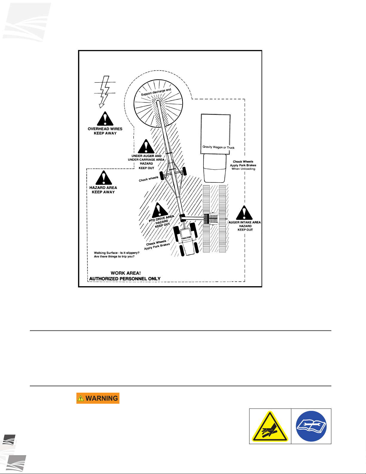
2.9. Work Area Safety ..................................................................................................... 9
2.10. Drives and Lockout Safety ................................................................................... 10
2.10.1. Hydraulic Power Safety ......................................................................... 10
2.11. Personal Protective Equipment (Required to be Worn) ...................................... 11
2.11.1. Safety Equipment Required.................................................................... 12
2.12. Safety Decals ....................................................................................................... 12
2.12.1. Decal Installation/Replacement .............................................................. 12
2.12.2. Safety Decal Locations and Details........................................................ 12
3. Assembly ............................................................................................................................ 17
3.1. Assembly Safety..................................................................................................... 17
3.2. General Assembly .................................................................................................. 17
3.3. Verify Auger Assembly ........................................................................................... 18
3.3.1. Replace the Short Truss Brace (130/160) ................................................ 18
3.3.2. Install the GULP2 Hopper Lift Arm (130/160).......................................... 20
3.4. GULP2 Hopper Assembly ...................................................................................... 21
3.4.1. Replace the Swing Tube Flight (130) ....................................................... 21
3.4.2. Remove the Transition (160) .................................................................... 21
3.4.3. Connect the GULP2 Transition to the Swing Tube (130) ......................... 21
3.4.4. Connect the GULP2 Transition to the Swing Tube (160) ......................... 23
3.4.5. Attach the GULP2 Hopper to the Transition (130/160)............................. 27
3.4.6. Install the 3-Spool Valve (130/160) .......................................................... 28
3.4.7. Attach the End Ramp (130/160) ............................................................... 29
3.4.8. Connect the Hydraulic Hoses to the 3-Spool Valve (130/160) ................. 30
3.5. Install the Hydraulic Winch (130/160)..................................................................... 32
4. Transport............................................................................................................................. 35
4.1. Transport Safety..................................................................................................... 35
4.2. Transport Procedure .............................................................................................. 35
5. Placement ........................................................................................................................... 39
5.1. Placement Safety ................................................................................................... 39
5.2. Placement .............................................................................................................. 39

WESTFIELD - GULP2 HOPPER
MKX130 AND MKX160 MODELS
430962 R1
6. Operation ............................................................................................................................ 41
6.1. Operating Safety..................................................................................................... 41
6.2. Start-up and Break-in ............................................................................................. 41
6.3. Operator Controls ................................................................................................... 42
6.4. Operation - Hydraulic Drive .................................................................................... 43
6.5. Set GULP2 Belt Speed.......................................................................................... 43
6.6. Emergency Shutdown ............................................................................................ 43
6.7. Restarting with a Full Tube..................................................................................... 44
6.8. Shutdown................................................................................................................ 44
6.9. Clean Out ............................................................................................................... 44
7. Maintenance........................................................................................................................ 45
7.1. Maintenance Safety................................................................................................ 45
7.2. Maintenance Intervals ............................................................................................ 45
7.3. Fluids and Lubricants ............................................................................................. 46
7.4. Maintenance Procedures........................................................................................ 46
7.4.1. Visual Inspection....................................................................................... 46
7.4.2. Hydraulic Hose and Coupler Inspection ................................................... 46
7.4.3. Machine Greasing..................................................................................... 46
7.4.4. Conveyor Belt Tension ............................................................................. 47
7.4.5. Conveyor Belt Alignment .......................................................................... 49
7.4.6. Inspect Belt Lacing ................................................................................... 50
7.4.7. Conveyor Belt Replacement ..................................................................... 51
8. Troubleshooting ................................................................................................................. 55
9. Appendix ............................................................................................................................. 57
9.1. Specifications ......................................................................................................... 57
9.2. Open/Closed-Center Valve Conversion ................................................................. 57
9.3. Tightening O-Ring Fittings...................................................................................... 58
9.4. Bolt Torque Values ................................................................................................. 59
Warranty.................................................................................................................................. 61

WESTFIELD - GULP2 HOPPER 1. INTRODUCTION
MKX130 AND MKX160 MODELS
30962 R1 5
1. Introduction
Thank you for purchasing a Westfield GULP2 Hopper. This equipment will allow safe
and efficient operation when you read and follow all of the instructions contained in this
manual. With proper care, your GULP2 Hopper will provide you with many years of
trouble-free operation.
Keep this manual handy for frequent reference and to review with new personnel. A
sign-off form is provided on the inside front cover for your convenience. If any infor-
mation in this manual is not understood or if you need additional information, please
contact your local distributor or dealer for assistance.
This manual should be regarded as part of the equipment. Suppliers of both new and
second-hand equipment are advised to retain documentary evidence that this manual
was provided with the equipment.
This manual describes the assembly and operation of the GULP2 Hopper, used as an
accessory on MKX130 and MKX160 grain augers, and is intended as a supplement to
your MKX Series Auger Operator Manual. Refer to the appropriate MKX Manual for
additional Operating and Maintenance instructions.
Figure 1.1 GULP2 Hopper
Serial Number:
*Serial number is located on the lower tube.
CONVEYOR BELT
CONVEYOR BELT
SIDE RAMP
END RAMP
POWER SWING
SWING TUBE
SWING TUBE TRANSITION
SIDE FLAPS CONTROL
SIDE FLAP
SIDE FLAP
HYDRAULIC
CONTROLS
DRIVE-OVER AREA

1. INTRODUCTION WESTFIELD - GULP2 HOPPER
MKX130 AND MKX160 MODELS
630962 R1

WESTFIELD - GULP2 HOPPER 2. SAFETY
MKX130 AND MKX160 MODELS
30962 R1 7
2. Safety
2.1. Safety Alert Symbol and Signal Words
This safety alert symbol indicates important safety messages in this manual. When you
see this symbol, be alert to the possibility of injury or death, carefully read the message
that follows, and inform others.
SIGNAL WORDS: Note the use of the signal words DANGER, WARNING, CAUTION,
and NOTICE with the safety messages. The appropriate signal word for each message
has been selected using the definitions below as a guideline.
Indicates an imminently hazardous situation that, if not avoided, will
result in serious injury or death.
Indicates a hazardous situation that, if not avoided, could result in
serious injury or death.
Indicates a hazardous situation that, if not avoided, may result in
minor or moderate injury.
Indicates a potentially hazardous situation that, if not avoided, may
result in property damage.
2.2. General Safety
The safety information found throughout this complete Safety Section of the manual
applies to all safety practices. Additional instructions specific to a certain safety practice
(such as Operation Safety), can be found in the appropriate section.
YOU are responsible for the SAFE use and maintenance of your equipment. YOU must
ensure that you and anyone else who is going to work around the equipment under-
stands all procedures and related SAFETY information contained in this manual.
Remember, YOU are the key to safety. Good safety practices not only protect you, but
also the people around you. Make these practices a working part of your safety program.
All accidents can be avoided.
• It is the equipment owner, operator, and maintenance personnel's respon-
sibility to read and understand ALL safety instructions, safety decals, and
manuals and follow them when assembling, operating, or maintaining the
equipment.
• Equipment owners must give instructions and review the information initially and
annually with all personnel before allowing them to operate this product. Untrained
users/operators expose themselves and bystanders to possible serious injury or
death.
• This equipment is not intended to be used by children.
• Use this equipment for its intended purposes only.
• Do not modify the equipment in any way without written permission from the manu-
facturer. Unauthorized modification may impair the function and/or safety, and could
affect the life of the equipment. Any unauthorized modification of the equipment will
void the warranty.

2. SAFETY WESTFIELD - GULP2 HOPPER
MKX130 AND MKX160 MODELS
830962 R1
2.3. Additional Safety Information
This manual is a supplement to the MKX Series Operator Manual. Please ensure that
you have read and understood that manual.
2.4. Rotating Flighting Safety
• KEEP AWAY from rotating flighting.
• DO NOT remove or modify flighting guards, doors, or
covers. Keep in good working order. Have replaced if
damaged.
• DO NOT operate the equipment without all guards,
doors, and covers in place.
• NEVER touch the flighting. Use a stick or other tool to remove an obstruction or
clean out.
• Shut off and lock out power to adjust, service, or clean.
2.5. Moving Conveyor Belt Safety
• DO NOT step on or touch moving conveyor belt.
• Shut off and lock out power to adjust, service, or clean.
2.6. Rotating Parts Safety
• Keep body, hair, and clothing away from
rotating pulleys, belts, chains, and sprock-
ets.
• Do not operate with any guard removed or
modified. Keep guards in good working
order.
• Shut off and remove key or lock out power source before inspecting or servicing
machine.

WESTFIELD - GULP2 HOPPER 2. SAFETY
MKX130 AND MKX160 MODELS
30962 R1 9
2.7. Guards Safety
• Install guards to prevent contact with moving parts.
• Do not operate equipment unless all guards are in place.
• Do not walk or step on guards.
• Lock out power before removing a guard.
• Ensure all guards are replaced after performing maintenance.
2.8. Hand Winch Safety
Where equipped:
• Inspect lift cable before using. Replace if frayed or damaged. Make sure lift cable is
seated properly in cable sheaves and cable clamps are secure.
• Tighten brake lock by turning winch handle clockwise at least two clicks after lower-
ing equipment.
• Lower equipment fully before towing, then rotate winch handle until cable has light
tension.
• Do not lubricate winch brake discs.
2.9. Work Area Safety
• Have another trained person nearby who can shut down the
equipment in case of accident.
• The work area should be kept clear of bystanders.
• Keep the work area clean and free of debris.

2. SAFETY WESTFIELD - GULP2 HOPPER
MKX130 AND MKX160 MODELS
10 30962 R1
Figure 2.1
2.10. Drives and Lockout Safety
Inspect the power source(s) before using and know how to shut down in an emergency.
Whenever you service or adjust your equipment, make sure you shut down and lock out
your power source to prevent inadvertent start-up and hazardous energy release. Know
the procedure(s) that applies to your equipment from the following power sources.
2.10.1. Hydraulic Power Safety
Power Source
• Refer to the rules and regulations applicable to the
power source operating your hydraulic drive.

WESTFIELD - GULP2 HOPPER 2. SAFETY
MKX130 AND MKX160 MODELS
30962 R1 11
• Do not connect or disconnect hydraulic lines while system is under pressure.
• Keep all hydraulic lines away from moving parts.
• Escaping hydraulic fluid under pressure will cause serious injury if it penetrates the
skin surface (serious infection or toxic reaction can develop). See a doctor immedi-
ately if injured.
• Use metal or wood as a backstop when searching for hydraulic leaks and wear
proper hand and eye protection.
• Check all hydraulic components are tight and in good condition. Replace any worn,
cut, abraded, flattened, or crimped hoses.
• Clean the connections before connecting to equipment.
• Do not attempt any makeshift repairs to the hydraulic fittings or hoses with tape,
clamps, or adhesive. The hydraulic system operates under extremely high pressure;
such repairs will fail suddenly and create a hazardous and unsafe condition.
Lockout
• Always place all hydraulic controls in neutral and relieve system pressure before dis-
connecting or working on hydraulic system.
2.11. Personal Protective Equipment (Required to be Worn)
Ear Protection
• Wear ear protection to prevent hearing damage.
Work Gloves
• Wear work gloves to protect your hands from sharp and rough edges.
Steel-Toe Boots
• Wear steel-toe boots to protect feet from falling debris.
Safety Glasses
• Wear safety glasses at all times to protect eyes from debris.
Dust Mask
• Wear a dust mask to prevent breathing potentially harmful dust.
Hard Hat
• Wear a hard hat to help protect your head.
Coveralls
• Wear coveralls to protect skin.

2. SAFETY WESTFIELD - GULP2 HOPPER
MKX130 AND MKX160 MODELS
12 30962 R1
2.11.1. Safety Equipment Required
First-Aid Kit
• Have a properly-stocked first-aid kit available for use should the need
arise, and know how to use it.
Fire Extinguisher
• Provide a fire extinguisher for use in case of an accident. Store in a highly
visible and accessible place.
2.12. Safety Decals
• Keep safety decals clean and legible at all times.
• Replace safety decals that are missing or have become illegible. See decal location
figures that follow.
• Replaced parts must display the same decal(s) as the original part.
• Replacement safety decals are available free of charge from your distributor,
dealer, or factory.
2.12.1. Decal Installation/Replacement
1. Decal area must be clean and dry, with a temperature above 50°F (10°C).
2. Decide on the exact position before you remove the backing paper.
3. Align the decal over the specified area and carefully press the small portion with the
exposed sticky backing in place.
4. Slowly peel back the remaining paper and carefully smooth the remaining portion of
the decal in place.
5. Small air pockets can be pierced with a pin and smoothed out using the sign backing
paper.
2.12.2. Safety Decal Locations and Details
Replicas of the safety decals that are attached to the equipment and their messages are
shown in the figure(s) that follow. Safe operation of the equipment requires that you
familiarize yourself with the various safety decals and the areas or particular functions
that the decals apply to, as well as the safety precautions that must be taken to avoid
serious injury, death, or damage.
Westfield reserves the right to update safety decals without notice. Safety decals may
not be exactly as shown.

WESTFIELD - GULP2 HOPPER 2. SAFETY
MKX130 AND MKX160 MODELS
30962 R1 13
Figure 2.2 Safety Decal Locations
Table 2.1 Safety Decal Description, Detail, and Location Information
Number Description Location Detail
20803 Missing guard hazard (Warning) Figure 2.2 Figure 2.3
20804 Entanglement hazard (Warning) Figure 2.2 Figure 2.4
20806 High pressure fluid hazard (Warning) Figure 2.2 Figure 2.5
20813 Rotating flighting hazard (Danger) Figure 2.2 Figure 2.6
21838 Pinch point (Caution) Figure 2.2 Figure 2.7
DANGER
ROTATING FLIGHTING HAZARD
To prevent death or serious injury:
• KEEP AWAY from rotating auger flighting.
• DO NOT remove or modify auger flighting guards,
doors, or covers. Keep in good working order. Have
replaced if damaged.
• DO NOT operate the auger without all guards, doors,
and covers in place.
• NEVER touch the auger flighting. Use a stick or other
tool to remove an obstruction or clean out.
• Shut off and lock out power to adjust, service, or clean.
Made in Canada 20813
WARNING
HIGH PRESSURE FLUID HAZARD
Hydraulic fluid can cause serious injury if it
penetrates the skin. If it does, see a doctor
immediately.
• Relieve pressure before unhooking hydraulic line.
• Wear proper hand and eye protection, and use wood
or cardboard, not hands, when searching for leaks.
60802adanaCniedaM
DECAL 20806
DECAL 20813
CAUTION
21838
Made in Canada
DECAL 21838
WARNING
MISSING GUARD HAZARD
To prevent serious injury or
death, shut off power and
reattach guard before operating
machine.
20803
Made in Canada
DECAL 20803
WARNING
ENTANGLEMENT HAZARD
To prevent serious injury or death:
• Keep body, hair, and clothing away from rotating
pulleys, belts, chains, and sprockets.
• Do not operate with any guard removed or
modified. Keep guards in good working order.
• Shut off and remove key or lock out power source
before inspecting or servicing machine.
Made in Canada 20804
DECAL 20804

2. SAFETY WESTFIELD - GULP2 HOPPER
MKX130 AND MKX160 MODELS
14 30962 R1
Figure 2.3 Decal #20803
Figure 2.4 Decal #20804
Figure 2.5 Decal #20806
WARNING
MISSING GUARD HAZARD
To prevent serious injury or
death, shut off power and
reattach guard before operating
machine.
20803
Made in Canada
WARNING
ENTANGLEMENT HAZARD
To prevent serious injury or death:
• Keep body, hair, and clothing away from rotating
pulleys, belts, chains, and sprockets.
• Do not operate with any guard removed or
modified. Keep guards in good working order.
• Shut off and remove key or lock out power source
before inspecting or servicing machine.
Made in Canada 20804
WARNING
HIGH PRESSURE FLUID HAZARD
Hydraulic fluid can cause serious injury if it
penetrates the skin. If it does, see a doctor
immediately.
• Relieve pressure before unhooking hydraulic line.
• Wear proper hand and eye protection, and use wood
or cardboard, not hands, when searching for leaks.
60802adanaCniedaM

WESTFIELD - GULP2 HOPPER 2. SAFETY
MKX130 AND MKX160 MODELS
30962 R1 15
Figure 2.6 Decal #20813
Figure 2.7 Decal #21838
DANGER
ROTATING FLIGHTING HAZARD
To prevent death or serious injury:
• KEEP AWAY from rotating auger flighting.
• DO NOT remove or modify auger flighting guards,
doors, or covers. Keep in good working order. Have
replaced if damaged.
• DO NOT operate the auger without all guards, doors,
and covers in place.
• NEVER touch the auger flighting. Use a stick or other
tool to remove an obstruction or clean out.
• Shut off and lock out power to adjust, service, or clean.
Made in Canada 20813
CAUTION
21838
Made in Canada

2. SAFETY WESTFIELD - GULP2 HOPPER
MKX130 AND MKX160 MODELS
16 30962 R1

WESTFIELD - GULP2 HOPPER 3. ASSEMBLY
MKX130 AND MKX160 MODELS
30962 R1 17
3. Assembly
Before continuing, ensure you have completely read and understood this manual’s
Safety chapter, in addition to the safety information in the section(s) below.
3.1. Assembly Safety
• Do not take chances with safety. The components can be large, heavy, and hard to
handle. Always use the proper tools, rated lifting equipment, and lifting points for the
job.
• Carry out assembly in a large open area with a level surface.
• Always have two or more people assembling the equipment.
• Make sure you have sufficient lighting for the work area.
• Tighten all fasteners according to their specifications. Do not replace or substitute
bolts, nuts, or other hardware that is of lesser quality than the hardware supplied by
the manufacturer.
3.2. General Assembly
The GULP2 hopper is available installed as part of the normal assembly of an MKX130
or MKX160 auger, as an option in place of the low profile hopper, or as a kit to replace an
already-installed low-profile hopper.
Refer to the appropriate assembly manual for general assembly information, including
auger assembly sequence and the standard list of tools required (installation of the
GULP2 hopper replaces the installation of the Low Profile hopper in the auger assembly
sequence).
See Table 3.1 for a list of assembly procedures required to assemble and install a
GULP2 hopper, presented in the sequence that they should be performed.
Table 3.1 GULP2 Assembly Procedures
#Procedures Page
1Verify Auger Assembly page 18
2Replace the Swing Tube Flight (130)apage 21
3Remove the Transition (160)apage 21
4Connect the GULP2 Transition to the Swing Tube (130)apage 21
5Connect the GULP2 Transition to the Swing Tube (160) page 23
6Attach the GULP2 Hopper to the Transition (130/160) page 27
7Install the 3-Spool Valve (130/160) page 28
8Attach the End Ramp (130/160) page 29
9Connect the Hydraulic Hoses to the 3-Spool Valve (130/160)bpage 30
10 Install the Hydraulic Winch (130/160) page 32
a. Only required for GULP2 kit to replace a low-profile hopper.
b. The 3-Spool hydraulic control valve can be converted between closed center and open center by installing
the appropriate conversion plug on the valve. See “Open/Closed-Center Valve Conversion” on page 57.

3. ASSEMBLY WESTFIELD - GULP2 HOPPER
MKX130 AND MKX160 MODELS
18 30962 R1
3.3. Verify Auger Assembly
During the assembly of the auger, the following standard parts must be replaced by parts
modified to be compatible with the GULP2 hopper:
• intake-side single cross brace
• lift arm (installed with hydraulic winch)
3.3.1. Replace the Short Truss Brace (130/160)
During the assembly of the auger, ensure that the standard single truss brace tube
closest to the boot is replaced by the short truss brace tube listed in Table 3.2 below.
1. Attach the GULP2 lift arm mount to lower-middle tube brackets:
a. for MKX130 use six 1/2" x 1-1/4" bolts and locknuts.
b. for MKX160 use six 1/2" x 1-1/2" bolts and locknuts.
2. MKX130 models: Position the new short truss brace tube between the truss
tower and lift arm mount, and secure it with a 1/2” x 1-1/2” bolt and locknut at
each end.
3. MKX160 models: Position the new short truss brace tube between the truss
tower and lift arm mount. Secure to the joiner plate using a 1/2" x 1-3/4" bolt
and locknut. Attach to the lift arm mount using a 3/4" locknut.
Table 3.2 Replacement Truss Brace Tube
Model Standard
Truss Brace Tube
GULP2 Short Truss Brace Tube
(Replacement)
130-84 10-20078 10-21489130-94
130-114 10-20254
160-105
160-125 10-20778 10-22417

WESTFIELD - GULP2 HOPPER 3. ASSEMBLY
MKX130 AND MKX160 MODELS
30962 R1 19
Figure 3.1 MKX130 Short Truss Brace Tube
Figure 3.2 MKX160 Short Truss Brace Tube
GULP2 HOPPER
SHORT TRUSS BRACE TUBE
GULP2
LIFT ARM MOUNT
LOW PROFILE HOPPER
LIFT ARM MOUNT
GULP2
LIFT ARM MOUNT
GULP2
LIFT ARM MOUNT
LOW PROFILE HOPPER
LIFT ARM MOUNT
GULP2 HOPPER
SHORT TRUSS BRACE TUBE
GULP2
LIFT ARM MOUNT

3. ASSEMBLY WESTFIELD - GULP2 HOPPER
MKX130 AND MKX160 MODELS
20 30962 R1
3.3.2. Install the GULP2 Hopper Lift Arm (130/160)
During the assembly of the auger, ensure that the standard lift arm is replaced by the lift
arm listed in Table 3.3 below.
1. Position the hopper lift arm assembly on the GULP2 lift arm mount bracket
with the arm overhanging the side of the auger that the hopper will be
operating on.
2. Fasten the hopper lift arm assembly to the mount bracket with two lift arm
attach pins (10-21575) and linch pins (10-29998).
Figure 3.3 GULP2 Hopper Lift Arm
Table 3.3 Replacement Lift Arm
Model Standard Lift Arm GULP2 Lift Arm (Replacement )
130 10-20030 10-21538
160 10-20663 10-21538
HOPPER LIFT ARM
GULP2 LIFT ARM MOUNT
ASSEMBLY
This manual suits for next models
1
Table of contents
Other Westfield Farm Equipment manuals
Popular Farm Equipment manuals by other brands

Gaspardo
Gaspardo NINA 250 Use and maintenance

Finn
Finn HydroSeeder T120 Operator Instructions And Parts Manual

Nogueira
Nogueira FTN-2500 instruction manual

Teagle
Teagle Tomahawk 8080S Instruction book / parts list

aivituvin
aivituvin AIR 55 instruction manual

Horizont Agrar
Horizont Agrar Scout N2 operating instructions