Westfield MK130 Plus Installation instructions

Part Number: 30259
Revised: 10/2/10
Read this manual before using product. Failure
to follow instructions and safety precautions can
result in serious injury, death, or property
damage. Keep manual for future reference.
GRAIN AUGERS
MK 130 PLUS X 61’ - 81’
ASSEMBLY & OPERATION

This product has been designed and constructed according to general engineering
standardsa. Other local regulations may apply and must be followed by the operator.
We strongly recommend that all personnel associated with this equipment be trained
in the correct operational and safety procedures required for this product. Periodic
reviews of this manual with all employees should be standard practice. For your
convenience, we include this sign-off sheet so you can record your periodic reviews.
a. Standards include organizations such as the American Society of Agricultural and Biological Engineers,
American National Standards Institute, Canadian Standards Association, International Organization for
Standardization, and/or others.
Date Employee Signature Employer Signature

30259 3
WESTFIELD GRAIN AUGERS
MK 130 PLUS X61’ - 81’
TABLE OF CONTENTS
1. Introduction .......................................................................................................................... 5
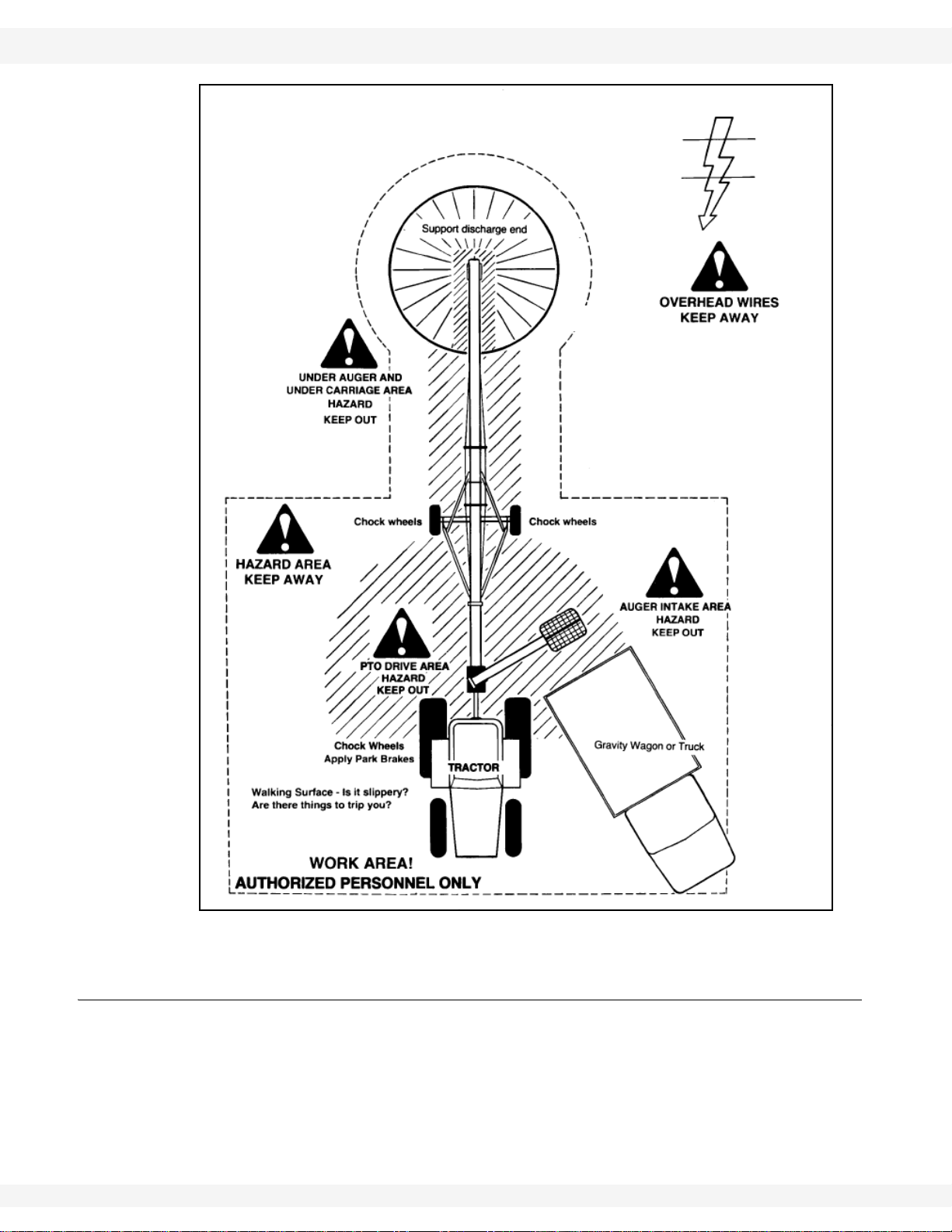
2. Safety First............................................................................................................................ 7
2.1. General Safety ......................................................................................................... 8
2.2. Assembly Safety....................................................................................................... 9
2.3. Operation Safety ...................................................................................................... 9
2.4. PTO Safety............................................................................................................. 10
2.5. Hydraulic Safety..................................................................................................... 11
2.6. Transport & Placement Safety ............................................................................... 12
2.7. ............................................................................................................................... 12
2.8. Maintenance Safety................................................................................................ 13
2.9. Safety Decal Locations........................................................................................... 13
2.9.1. Decal Installation...................................................................................... 13
2.9.2. Decal Locations........................................................................................ 13
3. Assembly ............................................................................................................................ 19
3.1. Tube and Flight ...................................................................................................... 19
3.2. Track Shoe, Trackstop, & Lift-Assist Arm............................................................... 20
3.3. Tow Bar.................................................................................................................. 22
3.4. Boot........................................................................................................................ 23
3.5. Discharge Spout..................................................................................................... 24
3.6. Thrust Adjuster....................................................................................................... 24
3.7. Truss ...................................................................................................................... 25
3.8. Transport Undercarriage ........................................................................................ 28
3.9. Lift Cylinder / Cable................................................................................................ 33
3.9.1. MK130 Plus 61’/71’................................................................................... 33
3.9.2. MK130 Plus 81’ ........................................................................................ 35
3.10. Hydraulic Hoses................................................................................................... 37
3.10.1. MK130 61’/71’......................................................................................... 37
3.10.2. MK130 81'............................................................................................... 38
3.11. PTO (CV) Driveline............................................................................................... 39
3.12. Standard Intake Hopper....................................................................................... 40
3.12.1. Hopper lift Extension .............................................................................. 43
3.12.2. Hopper Lift Arm / Winch ......................................................................... 43
3.13. Optional Low Profile Hopper ................................................................................ 44
3.14. Hitch Jack............................................................................................................. 46
3.15. Auger-to-Tractor Hookup...................................................................................... 47
3.15.1. PTO Driveline / Drawbar......................................................................... 47
3.15.2. Hydraulic Hose Couplers........................................................................ 49
3.16. Plastic Manual Holder .......................................................................................... 49
4. Transport & Placement...................................................................................................... 51
4.1. Transport Procedure .............................................................................................. 51
4.2. Placement Procedure............................................................................................. 53

430259
WESTFIELD GRAIN AUGERS
MK 130 PLUS X61’ - 81’
TABLE OF CONTENTS
5. Operation ............................................................................................................................ 57
5.1. Pre-Operation Checklist ......................................................................................... 57
5.2. Auger Drive & Lockout Procedure.......................................................................... 58
5.3. Hydraulics............................................................................................................... 58
5.4. Operating Procedure.............................................................................................. 59
5.4.1. Initial Start-Up........................................................................................... 59
5.4.2. Operating with a Full Load........................................................................ 59
5.4.3. Shutdown.................................................................................................. 60
5.4.4. Lowering & Completion............................................................................. 61
6. Maintenance & Storage...................................................................................................... 63
6.1. General Maintenance Procedures.......................................................................... 63
6.2. General Storage Procedure.................................................................................... 67
7. Troubleshooting ................................................................................................................. 69
8. Appendix............................................................................................................................. 73
8.1. Lift Cylinder Hydraulics........................................................................................... 73
8.2. Charging Lift System (MK130 Plus 81’ Only)......................................................... 73
Warranty.................................................................................................................................. 75

WESTFIELD - GRAIN AUGERS 1. INTRODUCTION
MK 130 PLUS X61’ - 81’
30259 5
1.Introduction
Congratulations. As the new owner of a grain auger, you will be working with
equipment designed to complement and improve your farming operation. Before
using this auger, please read this manual and all safety labels and familiarize
yourself with the various features of the machine and the necessary precautions
for efficient and safe operation.
In addition, anyone using this auger is required to comply with all safety precau-
tions in this manual and in safety labels attached to the auger. A sign-off form is
supplied on the inside front cover to record your safety reviews.
Thank you.
Serial Number:
*Serial number is located on the lower tube.

1. INTRODUCTION WESTFIELD - GRAIN AUGERS
MK 130 PLUS X61’ - 81’
630259

WESTFIELD - GRAIN AUGERS 2. SAFETY FIRST
MK 130 PLUS X61’ - 81’
30259 7
2.Safety First
The Safety Alert symbol to the left identifies important safety messages on the
product and in the manual. When you see this symbol, be alert to the possibil-
ity of personal injury or death. Follow the instructions in the safety messages.
Why is SAFETY important to you?
Three big reasons:
• Accidents disable and kill.
• Accidents cost.
• Accidents can be avoided.
SIGNAL WORDS
Note the use of the signal words DANGER, WARNING, CAUTION, and NOTICE
with the safety messages. The appropriate signal word for each message has
been selected using the definitions below as a guideline.
The Safety Alert symbol means ATTENTION, BE ALERT!, YOUR SAFETY IS
INVOLVED.
DANGER
Indicates an imminently hazardous situation
that, if not avoided, will result in serious injury
or death.
WARNING
Indicates a hazardous situation that, if not
avoided, could result in serious injury or
death.
CAUTION
Indicates a hazardous situation that, if not
avoided, may result in minor or moderate
injury.
NOTICE
Indicates a potentially hazardous situation that, if not
avoided, may result in property damage.

2. SAFETY FIRST WESTFIELD - GRAIN AUGERS
MK 130 PLUS X61’ - 81’
830259
2.1. GENERAL SAFETY
Important: The general safety section includes instructions that apply to all safety practices.
Any instructions specific to a certain safety practice (e.g., assembly safety), can
be found in the appropriate section. Always read the complete instructional
sections and not just these safety summaries before doing anything with the
equipment.
YOU are responsible for the SAFE use and maintenance of your equipment.
YOU must ensure that you and anyone else who is going to work around the
equipment understands all procedures and related SAFETY information
contained in this manual.
Remember, YOU are the key to safety. Good safety practices not only protect
you, but also the people around you. Make these practices a working part of your
safety program.
• It is the equipment owner and the operator's responsibility to read and under-
stand ALL safety instructions, safety decals, and manuals and follow them
before assembling, operating, or maintaining the equipment. All accidents
can be avoided.
• Equipment owners must give instructions and review the information initially
and anually with all personnel before allowing them to operate this product.
Untrained users/operators expose themselves and bystanders to possible
serious injury or death.
• Use this equipment for its intended purposes only.
• Do not modify the equipment in any way. Unauthorized modification may
impair the function and/or safety, and could affect the life of the equipment.
Any modification to the equipment voids the warranty.
• Do not allow children, spectators, or bystanders within the work area.
• Have a first-aid kit available for use should the need arise, and know how to
use it.
• Provide a fire extinguisher for use in case of an accident. Store in a highly vis-
ible place.
• Wear appropriate protective gear. This list includes, but
is not limited to:
• a hard hat
•gloves
• protective shoes with slip-resistant soles
• protective goggles
• hearing protection
• For Powered Equipment: before servicing, adjusting, or repairing powered
equipment, unplug, place all controls in neutral or off position, stop the engine
or motor, remove ignition key or lock out power source, and wait for all mov-
ing parts to stop.

WESTFIELD - GRAIN AUGERS 2. SAFETY FIRST
MK 130 PLUS X61’ - 81’
30259 9
• Follow good shop practices:
• keep service area clean and dry
• be sure electrical outlets and tools are properly
grounded
• use adequate light for the job at hand
• Think SAFETY! Work SAFELY!
2.2. ASSEMBLY SAFETY
• Read through the instructions to get to know the sub-assemblies and hard-
ware that make up the equipment.
• Do not take chances with safety. The components are large, heavy, and can
be hard to handle. Always use the proper tools, stands, jacks, and hoists for
the job.
• Always have 2 or more people assembling the equipment. Because of the
weight, do not attempt assembly alone.
2.3. OPERATION SAFETY
• Have another trained person nearby who can shut down the auger in case of
accident. Always work with a second trained person around augers.
• Do not operate with any of the safety guards removed.
• Keep body, hair, and clothing away from moving parts. Stay away from intake
during operation.
• Inspect lift cable before using auger. Replace if frayed or damaged. Make
sure it is seated properly in cable sheaves and cable clamps are secure.
• Operate auger on level ground free of debris. If ground is uneven, anchor the
auger to prevent tipping or upending.
• Augers are not insulated. Keep away from electrical lines. Electrocution can
occur without direct contact.
• Support the discharge end and/or anchor the intake end before operating to
prevent upending.
• Do not use auger as a hoist.
• Empty auger before raising or lowering.
• Lower auger at completion of operation or when not in use. Auger could drop
rapidly in case of cable break or hydraulic failure (where applicable).
• Do not get on or beneath auger when raising or lowering intake hitch jack, or
when auger is supported by hitch jack.
• Do not operate auger with the service or cleanout doors open or unlatched.

2. SAFETY FIRST WESTFIELD - GRAIN AUGERS
MK 130 PLUS X61’ - 81’
10 30259
Figure 2.1
2.4. PTO SAFETY
• Never use a PTO driveline without a rotating shield in good working order.
• Ensure PTO driveline is securely attached at both ends before operating.
• Before starting tractor, turn power to PTO to the off position (where applica-
ble).
• Keep body, hair, and clothing away from rotating PTO driveline.
• Ensure the driveline shields turn freely on driveline.
BIN

WESTFIELD - GRAIN AUGERS 2. SAFETY FIRST
MK 130 PLUS X61’ - 81’
30259 11
• Do not exceed operating speed of 540 rpm.
• Keep u-joint angles small and equal. Do not exceed recommended operating
length for PTO driveline.
2.5. HYDRAULIC SAFETY
• Wear proper hand and face protection when searching for hydraulic leaks.
Escaping fluid under pressure can penetrate the skin, causing serious injury
like gangrene. In case of accident, see a doctor immediately.
• Fluid leaks in the hydraulic lift cylinders or hoses will allow the auger to lower
inadvertently. Repair all leaks and breaks immediately. Rupture could cause
damage and/or personal injury.
• A hydraulic lift is faster than a conventional hand crank—always clear area of
personnel before raising or lowering.
• Do not disconnect hydraulic couplers when hydraulic system is pressurized.
For the correct procedure, consult this manual or your tractor manual.
• Relieve pressure before unhooking hydraulic lines.
• Inspect hydraulic fittings and hoses for damage on a daily basis. Repair if
damaged.
• Ensure that the hydraulic line is properly connected and secure.
• Keep hydraulic line away from moving parts.
• Clean connections before connecting to equipment.

2. SAFETY FIRST WESTFIELD - GRAIN AUGERS
MK 130 PLUS X61’ - 81’
12 30259
2.6. TRANSPORT & PLACEMENT SAFETY
• Transport auger in full down position with slight ten-
sion on cable.
• Properly place hitch pin and securely attach safety
chain. Use a type of hitch pin that will not allow
auger to separate from towing vehicle.
• Always attach an SMV (slow moving vehicle) sign
before transporting auger. Equip the auger with the
necessary lights for transportation where required
by law. Always use hazard warning flashers on the
tractor/towing vehicle when transporting unless
prohibited by law.
• Always travel at a safe speed, never exceeding 15
mph (24 km/hr). Reduce speed on rough surfaces
and be cautious when turning corners or meeting
traffic.
• Before raising/lowering/moving the auger, make
sure the area around the auger is clear of obstruc-
tions and/or untrained personnel. Never allow any-
one to stand on or beneath auger while
transporting or placing auger.
• Do not transport auger on slopes greater than 20°.
• Wheels must be free to move when raising or low-
ering auger.
• Never attempt to move auger manually. To do so
will result in serious injury.
• Before moving auger, check and double check for overhead obstructions and/
or electrical wires. Electrocution can occur without direct contact.
• Disconnect PTO driveline from tractor before moving auger or tractor and
secure in transport saddle (where applicable).
• Raise intake feed hopper into transport position and lock hopper lift winch
before transporting or moving auger. Intake feed side of hopper must face
main auger when in transport position.
• Do not operate auger with intake hopper in transport position. This will cause
damage to the u-joint.
2.7. MAINTENANCE SAFETY
• Shut down and lock out all power before attempting maintenance of any kind.
If applicable, disconnect PTO driveline from tractor or hydraulic hoses on
units with hydraulic drive hoppers.
• After maintenance is complete, replace and secure all safety guards and
safety devices, and if applicable, service doors and cleanout covers.
• Support auger tube before attempting maintenance on the undercarriage
assembly. Auger should be in full down position for maintenance.
ELECTROCUTION
HAZARD

WESTFIELD - GRAIN AUGERS 2. SAFETY FIRST
MK 130 PLUS X61’ - 81’
30259 13
• Use only genuine Westfield replacement parts or equivalent. Replacement
parts such as intake guards, pulley guards, PTO driveline shields, winches,
and lift cables must meet ASABE standards or serious injury may result. Use
of unauthorized parts will void warranty. If in doubt, contact Westfield or your
Westfield dealer.
• Do not modify any auger components without authorization from Westfield.
Modification can be dangerous and result in serious injuries.
2.8. SAFETY DECAL LOCATIONS
• Keep safety decals clean and legible at all times.
• Replace safety decals that are missing or have become illegible. See decal
location figures below.
• Replaced parts must display the same decal(s) as the original part.
• Safety decals are available from your distributor, dealer, or factory.
2.8.1. DECAL INSTALLATION
1. Decal area must be clean and dry, with a temperature above 10°C (50°F).
2. Decide on the exact position before you remove the backing paper.
3. Align the decal over the specified area and carefully press the small portion
with the exposed sticky backing in place.
4. Slowly peel back the remaining paper and carefully smooth the remaining
portion of the decal in place.
5. Small air pockets can be pierced with a pin and smoothed out using the sign
backing paper.
2.8.2. DECAL LOCATIONS
Replicas of the safety decals that are attached to the equipment are shown in the
figure(s) that follow. Good safety requires that you familiarize yourself with the
various safety decals and the areas or particular functions that the decals apply
to as well as the safety precautions that must be taken to avoid serious, injury,
death, or damage.
Please review the decals shown. If your auger does not have these decals, they
are available upon request. Please specify which decals you need.
* Westfield reserves the right to update safety decals without notice. Safety
decals may not be exactly as shown.

2. SAFETY FIRST WESTFIELD - GRAIN AUGERS
MK 130 PLUS X61’ - 81’
14 30259
Figure 2.2
DECAL #17698
DECAL #28615

WESTFIELD - GRAIN AUGERS 2. SAFETY FIRST
MK 130 PLUS X61’ - 81’
30259 15
Figure 2.3
DECAL #17098
DECAL #17093
(ON LOW PROFILE
ONLY)
DECAL #17097
DECAL #17398
DECAL #17096
PLACED ON MACHINE
BEHIND GUARD
DECAL #27709
DECAL #17101
NOTE: INCLINED HOPPER
SHOWN
DECAL
#17113

2. SAFETY FIRST WESTFIELD - GRAIN AUGERS
MK 130 PLUS X61’ - 81’
16 30259
Figure 2.4
PLACED ON
MACHINE BEHIND
DECAL #17107
DECAL #18859
DECAL
#19960
DECAL #17099
DECAL #17094
DECAL #27709 DECAL #17101
DECAL #17098
DECAL #17531

WESTFIELD - GRAIN AUGERS 2. SAFETY FIRST
MK 130 PLUS X61’ - 81’
30259 17
Figure 2.5
NOTE: THIS WARNING DECAL IS
ONLY INCLUDED ON AUGERS
81’ AND LONGER.
DECAL # 27516

2. SAFETY FIRST WESTFIELD - GRAIN AUGERS
MK 130 PLUS X61’ - 81’
18 30259

WESTFIELD - GRAIN AUGERS 3. ASSEMBLY
MK 130 PLUS X61’ - 81’
30259 19
3.Assembly
Before beginning assembly, familiarize yourself with all the sub-assemblies and
hardware making up the auger. Have all parts on hand and arrange them for
easy access. Carry out assembly in a large open area with a level surface.
Important: Always have 2 or more people assembling the equipment. Because of the
weight, do not attempt assembly alone.
Augers are available in various combinations. In most cases, the following
instructions will apply to all augers. Where the assembly information varies,
additional instructions will be included and will be indicated with an arrow.
3.1. TUBE AND FLIGHT
1. Position tube sections. Align tube sections on a flat surface or on a series of
benches.
• The MK130 Plus 61' has 3 tube sections.
• The MK130 Plus 71' has 4 tube sections.
• The MK130 Plus 81' has 4 tube sections.
Important: Refer to Figure 3.12 and 3.13 for correct positioning.
NOTE: When assembling more than 2 sections, start from spout end and work towards
hopper.
2. Screw or slide lower flight shaft onto upper flight shaft until flight ends butt
together and flighting spiral matches up. Secure with hardware listed in table
below. Repeat, if necessary, for any remaining flight shafts.
Warning: Before continuing, please reread the safety information relevant to this section at
the beginning of this manual. Failure to follow the safety instructions can result in serious
injury, death, or property damage.
WARNING
Donot drop. Damage to equipmentor serious
personal injury will result.

3. ASSEMBLY WESTFIELD - GRAIN AUGERS
MK 130 PLUS X61’ - 81’
20 30259
3. Slide tube sections together and
secure. Make sure to align upper
and lower track ends and then
tighten bolts. Secure with hardware
in table below.
3.2. TRACK SHOE, TRACKSTOP, & LIFT-ASSIST ARM
1. MK130 Plus 61’/71’: Slide the double roller track shoe onto track with cable
attach-rod towards auger intake (Figure 3.2). Attach the angle trackstop as
shown in Figure 3.3 using four 7/16” x 1-1/4” bolts and locknuts (see also
Figure 3.12).
Figure 3.1
Details for fastenings:
Auger For Flighting Amt For Tubes Amt
All • 5/8” x 4-1/2” GR8 bolts
and locknuts 2• 7/16” x 1-1/4” bolts and
locknuts 12
Auger Track Stop
61’ • 1st set of holes from top
71’ • 2nd set of holes from top
81’ • set of 8 holes grouped together
This manual suits for next models
2
Table of contents
Other Westfield Farm Equipment manuals