Westin 80-HBS306 User manual

1
Westin Automotive Products, Inc.
320 W. Covina Blvd
San Dimas, Ca. 91773
Thank You for choosing Westin products
For Additional installation assistance please call
Customer service (800) 793-7846
www.westinautomotive.com
P.N.: 75-B80003 Rev. B DATE: 06/26/15
INSTALLATION INSTRUCTIONS
AUTOMOTIVE PRODUCTS,
PRODUCT DESCRIPTION
Bed Safe Universal Fit
PART NUMBERS:
80-HBS306, 80-HBS307, 80-HBS308, 80-HBS312, 80-HBS338
ITEM QUANTITY DESCRIPTION TOOLS NEEDED
14ALUMINUM MOUNTING TABS 1/2” SOCKET
21ANGLED ALUMINUM MOUNTING BRACKET RATCHET
36PLUS NUTS 1/2” WRENCH
415/16” Nut 1/2” DRILL BIT
545/16” x 1 1/4” HEX HEAD SCREW DRILL
665/16” FLAT WASHER
765/16” LOCK WASHER
815/16” X 2” HEX HEAD SCREW
CONTENT
ITEM 1 ITEM 2 ITEM 3 ITEM 4
ITEM 5 ITEM 7
ITEM 6 ITEM 8

2
Westin Automotive Products, Inc.
320 W. Covina Blvd
San Dimas, Ca. 91773
Thank You for choosing Westin products
For Additional installation assistance please call
Customer service (800) 793-7846
www.westinautomotive.com
P.N.: 75-B80003 Rev. B DATE: 06/26/15
PROCEDURE
1. Remove contents from box, verify if all parts listed are present and free from damage.
Carefully read and understand all instructions before attempting installation.
Failure to identify damage before installation could lead to a rejection of any claim.
2. Position box in desired mounting location.
3. Slide a mounting plate into each open end of the front and rear stanchions. Align no further than the leading edge of the
slot in the mounting plate. Mark the slot, remove the mounting plate and drill 1/2” hole. (Be sure there are no wires, brake
lines, gas lines, etc., below before drilling) See Figure 1
4. Lightly tap Plus Nuts into the drilled holes. Follow Plus Nut installation procedure. See Figure 2
Plus Nut Installation Procedure:
A. Put the bolt, washer and 5/16” nut together in order (See Figure 2) and begin to hand tighten.
B. Drill 1/2” hole in truck bed.
C. Insert bolt 1-2 threads past the end of plus nut.
D. Insert plus nut assembly into the truck bed hole, hold bolt with a ratchet to keep it from turning.
E. Rotate nut with a wrench to lock the plus nut into the bed
C. Remove bolt, washer and 5/16” nut.
5. Place the mounting tab into the stanchion and locate slot in the tab over the Plus Nut. Secure mounting plate with 5/16”
X 1 1/4” hex head screw, flat washer, and lock washer. Complete this procedure on all four corners. See Figure 1
Fig. 1
Fig. 2

3
Westin Automotive Products, Inc.
320 W. Covina Blvd
San Dimas, Ca. 91773
Thank You for choosing Westin products
For Additional installation assistance please call
Customer service (800) 793-7846
www.westinautomotive.com
P.N.: 75-B80003 Rev. B DATE: 06/26/15
Alternative Rear Mount Instructions
1. Use this method if you have space constraints in the rear mounting of the unit. See Figure 3
2. Pull drawer out of unit, once drawer hits the positive stop, reach into the box and remove the stop by removing the bolts
with your 1/2” socket. Completely remove the drawer and set it aside.
3. Center the rear mounting bracket on the Bed Safe housing and mark two holes in the floor and two holes in the Bed Safe.
4. Drill 1/2” holes in all four locations. Note: After holes are drilled be sure to sweep out all shavings from inside the box,
failure to do so results in the drawer operating improperly and roughly.
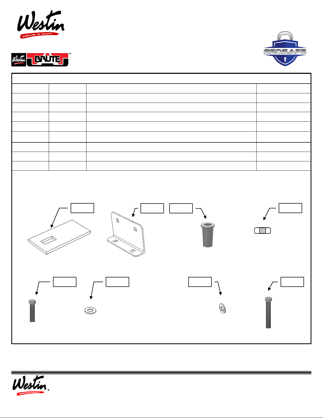
5. Place box back into position and install the plus nuts according to the “Plus Nut Installation Procedure” in step 4 of the
previous section. Put drawer back into position and reattach the positive drawer stop inside the box.
6. Secure using 5/16” x 1 1/4” hex head screws, flat washer and lock washer as seen in Figure 3.
Stacking Bed Safe Units Mount Instructions
1. Once lower Bed Safe is properly installed, place the next Bed Safe on top and use the angled mounting plate to attach the
two units in the rear section. Use previously stated “Plus Nut Installation Procedure”. See Figure 4.
2. Remove the top drawer stop and remove and set aside the drawer. Remove the two conveyer rollers and mark the outer
slots. Remove the top box and drill 1/2” holes then follow the “Plus Nut Installation Procedure”. See Figure 5
3. At this point remove all shavings from the drilling process from both boxes, failure to do so results in the drawer operating
improperly and roughly.
4. Secure all six locations with 5/16” x 1 1/4” hex head screws, lock washers, and flat washers.
5. Replace conveyer rollers, put drawer back into position and reattach the positive drawer stop inside the box. Failure to
replace stop could result in the drawer falling out of the case and possibly personal injury.
Fig. 3
REAR
REAR
Plus Nuts In-
Fig. 4
FRONT
Fig. 5
Front Mounting Location

4
Westin Automotive Products, Inc.
320 W. Covina Blvd
San Dimas, Ca. 91773
Thank You for choosing Westin products
For Additional installation assistance please call
Customer service (800) 793-7846
www.westinautomotive.com
P.N.: 75-B80003 Rev. B DATE: 06/26/15
Failure to follow these instructions could lead to death, personal injury, and / or property damage.
FASTENERS:
All Westin supplied fasteners must be utilized and installed in accordance with the installation in-
structions and apply torque to the specifications as defined. DOUBLE CHECK ALL FASTENERS
BEFORE INITIAL USE, AND PERIODICALLY IN THE FUTURE TO ENSURE PROPER FUNCTION
AND SAFETY.
DRILLING:
Most Westin products do not require drilling for installation. If drilling is defined as required, use
caution when drilling a vehicle. FAILURE TO REVIEW AN AREA TO BE DRILLED MAY RE-
SULT IN PERSONAL INJURY AND/OR INJURY TO OTHERS AS WELL AS VEHICLE DAMAGE.
EYE PROTECTION:
ALWAYS WEAR SAFETY GLASSES OR GOGGLES DURING THE INSTALLATION PROCESS TO
AVOID PERSONAL INJURY.
MAXIMUM TOWING/CARRYING CAPACITY:
The Westin Receiver Hitches will have a visible tow rating label affixed directly on the product. Us-
er should never exceed the vehicle manufacturers maximum tow and weight rating regardless of
the capacity of the hitch. FAILURE TO FOLLOW THESE GUIDELINES WILL VOID THE WESTIN
WARRANTY AND MAY RESULT IN PERSONAL INJURY AND/OR INJURY TO OTHERS AS WELL AS
VEHICLE DAMAGE.
WARNING
AUTOMOTIVE PRODUCTS, INC.
CARE INSTRUCTIONS
REGULAR WAXING IS RECOMMENDED. DO NOT USE ANY TYPE OF POLISH OR WAX THAT MAY CONTAIN ABRASIVES.
STAINLESS STEEL PRODUCTS CAN BE CLEANED WITH MILD SOAP AND WATER. STAINLESS STEEL POLISH SHOULD BE USED TO POLISH SMALL SCRATCHES.
GLOSS BLACK FINISHES SHOULD BE CLEANED WITH MILD SOAP AND WATER.
This manual suits for next models
4
Table of contents