manuals.online logo
Brands
  1. Home
  2. •
  3. Brands
  4. •
  5. WHD
  6. •
  7. Receiver
  8. •
  9. WHD BTR 55 User manual

WHD BTR 55 User manual

Manual BTR 55
applicable for
124-055-03-012-00, 124-055-03-015-00, 124-055-05-012-00, 124-055-06-012-00
Version (Technical and optical modifications reserved)
29.03.2022
Seite 1 von 8
1
.
Introduction
Thank you for buying this quality WHD roduct. Please read this manual carefully, es ecially the safety
and security information.
Please check that you have the correct manual for your roduct. To do this, lease com are the roduct
code number shown above with the roduct code number dis layed on your roduct.
2. ontents heck List
- BTR 55
- 2 ieces, PT screws 3x16
- Silicone tube (length: 250 mm)
- 2 ieces, cardboard distance rings
- Manual
3. Safety & s
ecurity
Important information
In addition to this guidance lease com ly with your own country-s ecific safety & security regulations.
3.1.
How to use this guide:
Read these instructions carefully before use and use this roduct only in accordance with the instructions
listed here.
3.2. Signs & symbols used
This sign warns of the danger of injury and ro erty damage.
This sign warns of injury arising from electricity.
This sign warns of injury and/or ex losion.
This symbol refers to additional information.
3.3. Signal words and their meaning
Danger: Potential severe hysical damage and acute danger.
Warning: Potential electrical shock hysical damage and severe ro erty damage.
aution: Potential fire hazard, hysical damage or ro erty damage as a result thereof.
Attention: Advisory notes only.
Manual BTR 55
applicable for
124-055-03-012-00, 124-055-03-015-00, 124-055-05-012-00, 124-055-06-012-00
Version (Technical and optical modifications reserved)
29.03.2022
Seite 2 von 8
Warning
The 230V ower line is only ermitted to be connected by a qualified rofessional electrician.
The electrical su ly must be disconnected before working on the device.
Improper handling may void warranty.
4. Product Scope
The BTR-55 is a stereo Bluetooth receiver. You can connect it to an audio device to lay music from any
Bluetooth-enabled device, which corres onds to the standard A2DP.
5. Intended use
Indoors, flush mounted socket.
6. Improper use
The device is not suitable for outdoor o eration.
The ambient air tem erature should not exceed 30 ° C.
7.
BTR 55 s
pecifications
Su ly Voltage
230 V AC, 50 Hz
Out ut
2 x
1.
2 watt
S eaker Im edance
2 x 4
ohms
Im edance Line-Out 470 ohms
THD
Ty
e
: 0.
5 % @ 1 kHz
Frequency Range
30 Hz ~ 20 kHz /
-
3 dB
Out ut Voltage Line
-
Out
0.
2 V AC (de ends on mobile device)
SNR S eaker: 70 dB
Line
-
Out: 70 dB
Bluetooth Version
Bluetooth V
3.0 EDR
Bluetooth Profile
A2DP
Bluetooth Frequency 2.4GHz-2.4835GHz
Maximum distance between
transmitter and receiver
10 m, Class II
AC Power (O eration mode)
6 VA
AC Power (Stand
-
By)
<
0.
5 VA
Protection Class
II
Dimensions
55×55×36 mm
De th
36 mm
Weight
100 g
O erating Tem erature
+5°C to
+45°C
Manual BTR 55
applicable for
124-055-03-012-00, 124-055-03-015-00, 124-055-05-012-00, 124-055-06-012-00
Version (Technical and optical modifications reserved)
29.03.2022
Seite 3 von 8
8. Preparatory work before installation
Un ack the unit carefully and kee the original ackaging (for future return under warranty if required).
Read the instructions carefully before installation.
Install the ower cable for 230 VAC and the RCA cable (for the music centre AUX-in) in accordance with
installation guidelines, and your desired ort scenario.
If necessary, hire a rofessional com any for installation, configuration and im lementation.
9. Installing the device
The Bluetooth receiver is mounted in an in-wall box with a 60 mm diameter. It has a built-in stereo
am lifier with a direct connection for the s eakers. A se arate line-out out ut allows connection to a
stereo system or multi-room system. The Bluetooth transmitter is integrated on the front of the device.
Note:
The unit must be ermanently installed.
For installation, a recessed box with a 60 mm diameter is required. Two PT screws, 3 x 14 are included.
9.1. onnections
When looking at the front of the BTR 55 the connectors
are located as follows:
Left side connections:
LINE OUT L (left)… above
LINE OUT R (right)… below
Right side connections:
S eaker L (left)… above
S eaker R (right)… below
The connector for 230V AC is located on the to .
The cables are fixed using screw-ty e terminal connectors.
Remove the front late.
The screw-ty e terminals are now accessible.
Note:
The screw-ty e terminals for 230 VAC are slightly recessed
in the housing.
Manual BTR 55
applicable for
124-055-03-012-00, 124-055-03-015-00, 124-055-05-012-00, 124-055-06-012-00
Version (Technical and optical modifications reserved)
29.03.2022
Seite 4 von 8
9.2. onnecting power supply
Connecting the 230 VAC cable:
Plug the cable into the screw-ty e terminal and fasten it
firmly with the screws on the front.
Note:
To rotect the device against electromagnetic interference
there is the silicone tube. Cut it into 2 ieces and run the
wires (L) and (N) of the 230V cable through the tubes
before connecting them on the terminal.
Push the silicone tube as far as ossible towards the
terminal.
Attention:
When connecting the su ly voltage (230V ~ / 50Hz), the
electrical system must be voltage free.
The su ly line must be rotected with a circuit breaker
(max. 16A).
9.3. onnecting Line
-
Out
Connect the Line-Out terminals when needed to your
audio system.
Plug the RCA cable into the terminal and screw it firmly
with the screws on the front.
Note:
For connecting the Line-Out orts only use shielded
cables. The shield of the cable has to be connected to the
earth-terminal.
Manual BTR 55
applicable for
124-055-03-012-00, 124-055-03-015-00, 124-055-05-012-00, 124-055-06-012-00
Version (Technical and optical modifications reserved)
29.03.2022
Seite 5 von 8
9.4. onnecting the speakers
Connect the s eakers to the screw-ty e terminals
rovided.
Plug the s eaker cable into the screw-ty e terminal and
fasten it firmly with the screws on the front.
Note:
The s eakers must be connected with se arate wires.
Never use the same wires.
The s eaker im edance must be a minimum of 4 ohms
(i.e.: you can connect one 4ohm s eaker or two 8ohm
s eakers arallel). Please observe the correct olarity.
9.5.
Mounting
Screw the flush mounting unit of the BTR-55 su lied with
the PT-screws into the wall outlet.
After the flush-mounted unit, the frame and the su lied
front anel can be cli ed on.
Height differences between the front anel and frame can
be offset by the com ensation frame rovided under the
sco e of delivery. The dimensions of the front anel are 55
x 55 mm.
Note:
The frame is not art of the device. It must be ordered
according to the chosen rogram switches from the switch
manufacturer.
Manual BTR 55
applicable for
124-055-03-012-00, 124-055-03-015-00, 124-055-05-012-00, 124-055-06-012-00
Version (Technical and optical modifications reserved)
29.03.2022
Seite 6 von 8
10. Operation
10.1.
Turn
ing
ON the BTR 55
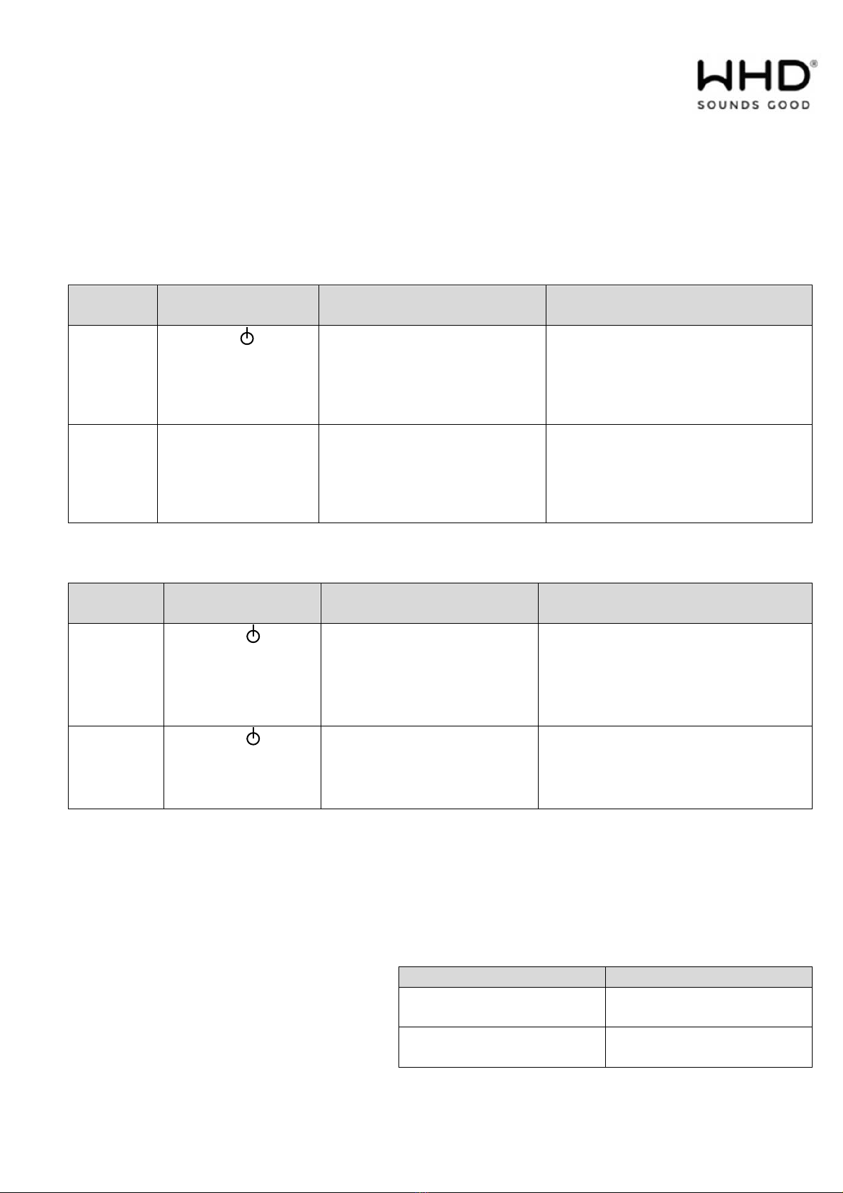
Press the ON/OFF button (Symbol ) for 3-5 seconds
until the blue status LED flashes constantly.
10.2. Turn OFF the BTR 55
Press the ON/OFF button (symbol ) for 3-5 seconds
until the blue status LED blinks several times and turns off.
10.3. Pairing with a Bluetooth
-
enabled
device
Turn ON the BTR 55 with the ON/OFF button (Symbol ).
Now ress the ON/OFF button (Symbol ) again for 6-7 seconds until the blue status LED blinks
constantly. Now the Pairing can be executed.
Note:
- The BTR 55 can handle and save a maximum of 8 separate Pairings to Bluetooth-enabled devices.
When adding a new device, the first Pairing will be overwritten.
- The BTR 55 is always in “searching mode” after turned on (briefly ressing the ON/OFF button
(Symbol ))
Note the following advice
for Pairing
Make sure that your Bluetooth device enables A2DP s ecifications according to IEEE 802.15.1. The
Pairing itself may be different concerning manufacturer or device.
Read the user manual of your Bluetooth-enabled device carefully!
Pairing in general:
1. There must be line of sight connection when the Pairing is erformed. Make sure that there is a
maximum distance of not more than 1m between the BTR 55 and your Bluetooth-enabled device.
2. Activate the Pairing Mode on the BTR 55 (LED is blinking).
3. Activate the Bluetooth Mode of your mobile device and start the SEARCH function for other
Bluetooth equi ment. The BTR 55 will show as „WHD BTR 55“. Select and continue.
4. If there is a assword needed, lease enter „0000“.
5. When the connection is established the blue status LED is constantly on.
Note:
- After the first Pairing with an external device the BTR 55 identifies the mobile device and no future
Pairing is necessary.
- To reconnect the devices, select them on the smart hone/tablet BTR55.
Manual BTR 55
applicable for
124-055-03-012-00, 124-055-03-015-00, 124-055-05-012-00, 124-055-06-012-00
Version (Technical and optical modifications reserved)
29.03.2022
Seite 7 von 8
10.4. Operation
The volume and track selection are erformed through the music source (Bluetooth-enabled mobile
device).
When you first use a new mobile device
Operation
on the
BTR 55
Operation
on the mobile device
LED
s
tatus
Pairing
Press the …
ON/OFF
button (> 6 sec.)
Search with your mobile
device for the Bluetooth
receiver BTR 55. This will
show u under the name
"
WHD BTR 55
".
blinking
onnect
- Select the BTR 55. When a
request for the assword
a ears, then confirm with
"0000".
If
connected
, the LED is constantly
on.
Use with already paired mobile devices
Operation
on the BTR 55
Operation
on the mobile device
LED s
tatus
Turn ON
BTR 55 &
connect
Press the …
ON/OFF button
(3-5 sec until the
LED is 2 x fast
blinking
)
- If
connected
, the LED is constantly
on.
Turn OFF
BTR 55 Press the …
ON/OFF button
about 3-5 sec.
Or cut connection on your
mobile device
LED turns off.
Note:
If you have lost contact with the BTR 55 longer than 20 minutes (outside the radio range), the connection
must be re-established. The airing is maintained.
10.
5
. LED Status Signals
Blue LED Signal
Status
blinking
Pairing Mode
LED constantly on Connected,
m
usic is transmitted
Manual BTR 55
applicable for
124-055-03-012-00, 124-055-03-015-00, 124-055-05-012-00, 124-055-06-012-00
Version (Technical and optical modifications reserved)
29.03.2022
Seite 8 von 8
11. Disposal
WHD are members of the INTERSEROH association.
We participate in the dual system as well as other
industry-specific solutions. Therefore, plastic, metal and
electronic parts can all be recycled.
12.
Declaration of onformity
This roduct su orts all CE-marking criteria.
The declaration of conformity certificate can be obtained
from
WHD
13. Name and address of the manufacturer
ONTA T
WHD - Wilhelm Huber+Söhne GmbH+Co.KG
Bismarckstr. 19
D-78652 Deißlingen
Fon +49 (0) 74 20 / 8 89-0
Fax +49 (0) 74 20 / 8 89-51
E-Mail: [email protected]
Home age: www.whd.de
Support
Fon +49 (0) 74 20 / 8 89-800
Fax +49 (0) 74 20 / 8 89-700
E-Mail: su ort@whd.de

This manual suits for next models

4

Other WHD Receiver manuals

WHD AirBridge PRO User manual

WHD

WHD AirBridge PRO User manual

WHD BTR 405 User manual

WHD

WHD BTR 405 User manual

WHD WR 205 L User manual

WHD

WHD WR 205 L User manual

WHD WR 225 HS User manual

WHD

WHD WR 225 HS User manual

WHD AirBridge plus User manual

WHD

WHD AirBridge plus User manual

WHD ACKPORT BT User manual

WHD

WHD ACKPORT BT User manual

WHD WR 205 User manual

WHD

WHD WR 205 User manual

WHD AirBridge User manual

WHD

WHD AirBridge User manual

WHD WR 205 User manual

WHD

WHD WR 205 User manual

WHD HLS 51 Radio Manual

WHD

WHD HLS 51 Radio Manual

WHD BTR 405 LV User manual

WHD

WHD BTR 405 LV User manual

Popular Receiver manuals by other brands

Xvive P3 user manual

Xvive

Xvive P3 user manual

Sherwood RV-5050RDS operating instructions

Sherwood

Sherwood RV-5050RDS operating instructions

Sony STR-DN1050 Help guide

Sony

Sony STR-DN1050 Help guide

RITS-N TS100 manual

RITS-N

RITS-N TS100 manual

Rockford Fosgate punchPMX-3 Installation & operation

Rockford Fosgate

Rockford Fosgate punchPMX-3 Installation & operation

LG LH-790HTS owner's manual

LG

LG LH-790HTS owner's manual

Sony STR-D2090 operating instructions

Sony

Sony STR-D2090 operating instructions

Permobil 1825342 manual

Permobil

Permobil 1825342 manual

HOME2US 8800 IR user manual

HOME2US

HOME2US 8800 IR user manual

Shure SVX Wireless manual

Shure

Shure SVX Wireless manual

ZoneVu ZVR-410 user manual

ZoneVu

ZoneVu ZVR-410 user manual

Vislink HDR-1000 User and technical manual

Vislink

Vislink HDR-1000 User and technical manual

Extron electronics XTP SR HDMI user guide

Extron electronics

Extron electronics XTP SR HDMI user guide

Onkyo HT-RC330 instruction manual

Onkyo

Onkyo HT-RC330 instruction manual

Harman Kardon AVR 225 reference guide

Harman Kardon

Harman Kardon AVR 225 reference guide

Cisco D9854 Installation and configuration guide

Cisco

Cisco D9854 Installation and configuration guide

Onkyo TX-DS474 instruction manual

Onkyo

Onkyo TX-DS474 instruction manual

Topfield TBF - 7110 user guide

Topfield

Topfield TBF - 7110 user guide

manuals.online logo
manuals.online logoBrands
  • About & Mission
  • Contact us
  • Privacy Policy
  • Terms and Conditions

Copyright 2025 Manuals.Online. All Rights Reserved.