Whitehall Manufacturing T-4-S Operation and maintenance manual

INSTRUCTIONS FOR
OPERATION AND CARE OF
Stationary 4 Pack
Thermalator
Model T-4-S
Stationary 4 Pack
Thermalator, 220 Volt
Model ET-4-S
6701-100-000
800-782-7706 • 626-968-6681 • www.whitehallmfg.com
P.O. Box 3527 • City of Industry, CA, 91744-0527, U.S.A.
Division of
®
Acorn Engineering Company
Revised: March 2015

WHITEHALL MANUFACTURING • P.O. BOX 3527 • City of Industry, CA 91744-0527 U.S.A
Phone (800) 782-7706 • (626) 968-6681 • Fax (626) 855-4862 • Web: www.whitehallmfg.com
a
Failure to follow these instructions could result in damage
to your new heating appliance and/or injury
! !
PLEASE READ THIS ENTIRE
BOOKLET BEFORE OPERATING
YOUR NEW THERMALATOR
This symbol on the product or on its packaging indicates that this product must not be disposed of with regular waste. Instead,
it is the user's responsibility to dispose of waste equipment according to the local laws. Separate collection and recycling of
the waste equipment at the time of disposal will help conserve natural resources and ensure it is recycled in a manner that
protects human health and the environment. For information about where the user can drop off the waste equipment for
recycling, please contact your local waste collection authority. See Page 14 for instructions on how to disassemble the
equipment for recycling purposes.
The presence of the CE Mark on Whitehall equipment means that it has been designed, tested and certified as complying
with all applicable European Union regulations and recommendations.
Waste Electrical and Electronic Equipment (WEEE)
General Warning or Caution
Electric Shock
European Union CE Mark
The Exclamation Symbol appears in Warning and Caution statements. This symbol designates where personal injury or
damage to the equipment is possible.
The Electric Shock Symbol is used to indicate a hazard arising from dangerous voltage. Any mishandling could result in
irreparable damage to the equipment and/or personal injury or death.
WARNING
To avoid electric shock, connect the instrument to properly earth-grounded, GFCI protected, 3-prong
receptacles only. Failure to observe this precaution can result in severe injury.
ŸDO NOT operate the appliance without properly filling with water. Under no circumstance should the appliance be
operated without water, as operating the appliance without water may result in damage to the heating element. Fill
appliance with water to the prescribed level before plugging into an electrical receptacle.
ŸCONNECT the appliance into a properly polarized G.F.C.I. (Ground Fault Circuit Interrupter) electrical receptacle for
protection against electrical shock. Have a qualified electrician verify the wall socket is properly polarized and grounded.
Use only the power cordset provided with the unit. The Thermalator appliance must be properly grounded.
ŸAVOID skin contact with HOT water at all times! Carefully place thermal packs into the Thermalator to avoid splashing onto
skin or coming into contact with HOT water. DO NOT reach into HOT water with bare hands to remove heated thermal
packs. Use a grasping device, such as tongs, to remove thermal packs from HOT water.
ŸDO NOT use in the presence of flammable liquids or gases, as these may present a fire and/or explosion hazard.
ŸALWAYS allow the appliance to cool down before draining water or moving unit.
ŸDO NOT use the lid knob to lift or transport appliance. Use the side handles to lift or move.
ŸNEVER leave appliance operating unattended for long periods of time. Water can evaporate and cause appliance to over-
heat which may result in damage to the heating element. Turn "OFF" when not in use.

WHITEHALL MANUFACTURING • P.O. BOX 3527 • City of Industry, CA 91744-0527 U.S.A
Phone (800) 782-7706 • (626) 968-6681 • Fax (626) 855-4862 • Web: www.whitehallmfg.com
Instructions for Operation and Care of Stationary 4 Pack Thermalator
1
TABLE OF CONTENTS
DESCRIPTION .......................................2
OPERATOR
INSPECTING THE THERMALATOR .......................3
SET UP INSTRUCTIONS . . . . . . . . . . . . . . . . . . . . . . . . . . . . . . 3-6
Setting up . . . . . . . . . . . . . . . . . . . . . . . . . . . . . . . . . . . . . . . . . 3
Filling my unit . . . . . . . . . . . . . . . . . . . . . . . . . . . . . . . . . . . . . . 4-5
Emptying my unit . . . . . . . . . . . . . . . . . . . . . . . . . . . . . . . . . . . . . 5
USING YOUR THERMALATOR . . . . . . . . . . . . . . . . . . . . . . . . . . 6-8
How do I use the Thermal Packs? . . . . . . . . . . . . . . . . . . . . . . . . . . . 6-7
How do I change the temperature? . . . . . . . . . . . . . . . . . . . . . . . . . . . . 8
How do I use different size Thermal Packs? . . . . . . . . . . . . . . . . . . . . . . . 8
MAINTENANCE ......................................9
CLEANING..........................................9
STORAGE ..........................................9
TROUBLESHOOTING .................................10
TECHNICAL INFORMATION ..........................11-13
Exploded view . . . . . . . . . . . . . . . . . . . . . . . . . . . . . . . . . . . . . . 11
Replacement parts (T-4-S) . . . . . . . . . . . . . . . . . . . . . . . . . . . . . . . 12
Replacement parts (ET-4-S) . . . . . . . . . . . . . . . . . . . . . . . . . . . . . . . 13
Electrical Parts Disassembly. . . . . . . . . . . . . . . . . . . . . . . . . . . . . . . 14
SKILLS AND TRAINING . . . . . . . . . . . . . . . . . . . . . . 3

WHITEHALL MANUFACTURING • P.O. BOX 3527 • City of Industry, CA 91744-0527 U.S.A
Phone (800) 782-7706 • (626) 968-6681 • Fax (626) 855-4862 • Web: www.whitehallmfg.com
2
Congratulations on receiving your Stationary 4 Pack Thermalator.
Your Thermalator is a simple and trouble-free unit to operate. The tank body, lid, bottom and tank housing are all made from
type 304 stainless steel. The controls are an ON/OFF switch on the front of the unit and a thermostat on the rear to control the
water temperature. Unit is preset set to a normal operating temperature.
Side handles and a knob on the lid minimize contact with the hot surface. The unit has Thermal Packs with blue and white tabs
and a stainless steel rack adapter that fits onto a vinyl coated wire rack. Inside the unit is a heating element and a temperature
sensor.
Instructions for Operation and Care of Stationary 4 Pack Thermalator
Blue tabs
Small wire rack
Thermal
Pack
Rack
Adapter
Lid
ON/OFF
Switch
Power Cord
Model T-4-S
100-120 Volts, 50/60 Hz,
8.33 Amps
Model ET-4-S
200-240 Volts, 50/60 Hz,
4.16 Amps

WHITEHALL MANUFACTURING • P.O. BOX 3527 • City of Industry, CA 91744-0527 U.S.A
Phone (800) 782-7706 • (626) 968-6681 • Fax (626) 855-4862 • Web: www.whitehallmfg.com
3
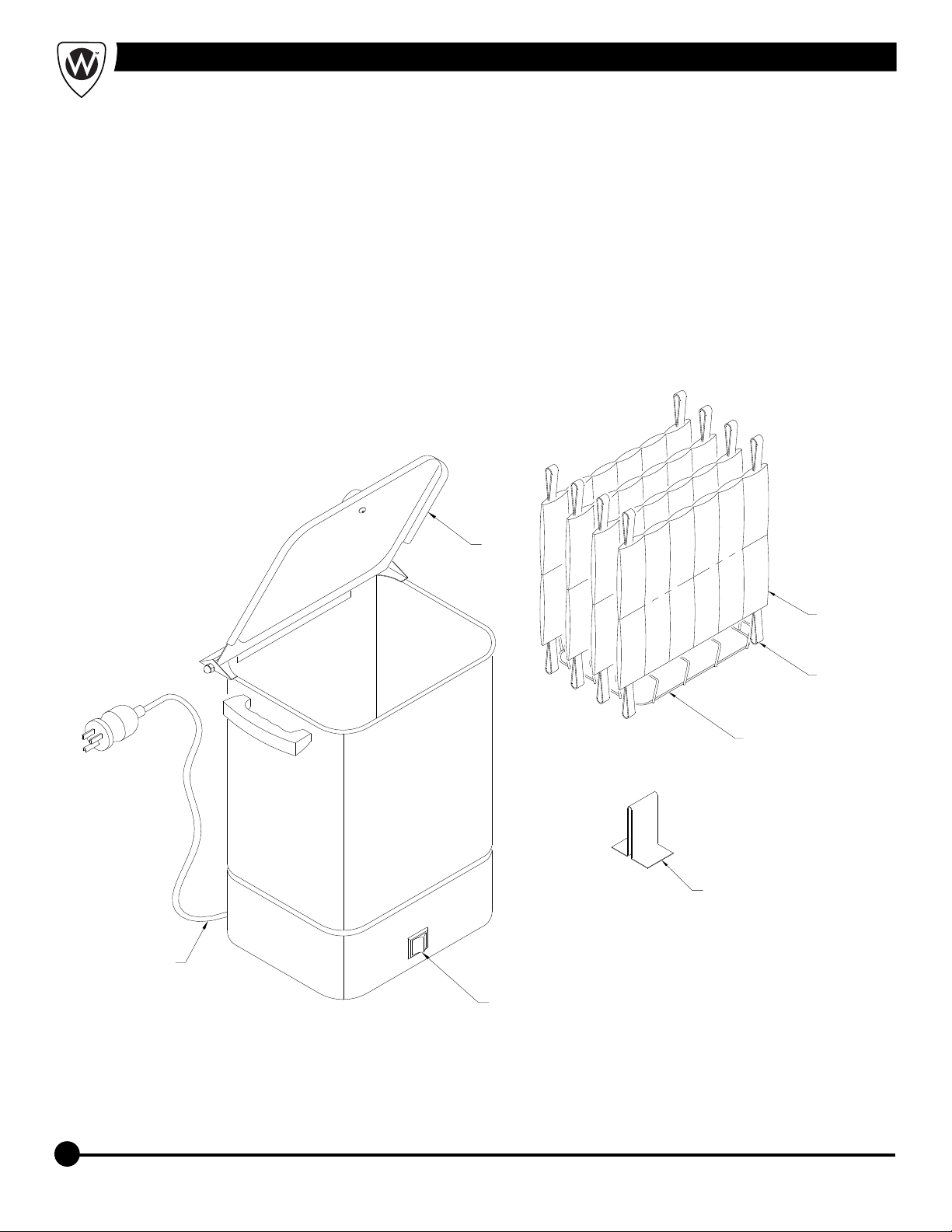
1 Thermalator Model T-4-S or ET-4-S
4 Thermal Packs (4 Standard)
1 Wire Rack - Small, Vinyl Coated
1 Rack Adapter (stainless steel)
1 Thermostat Knob
1 Warranty Registration Card
1 Instructions for Operation and Care
If you are missing anything, please call the phone
number listed on the back page.
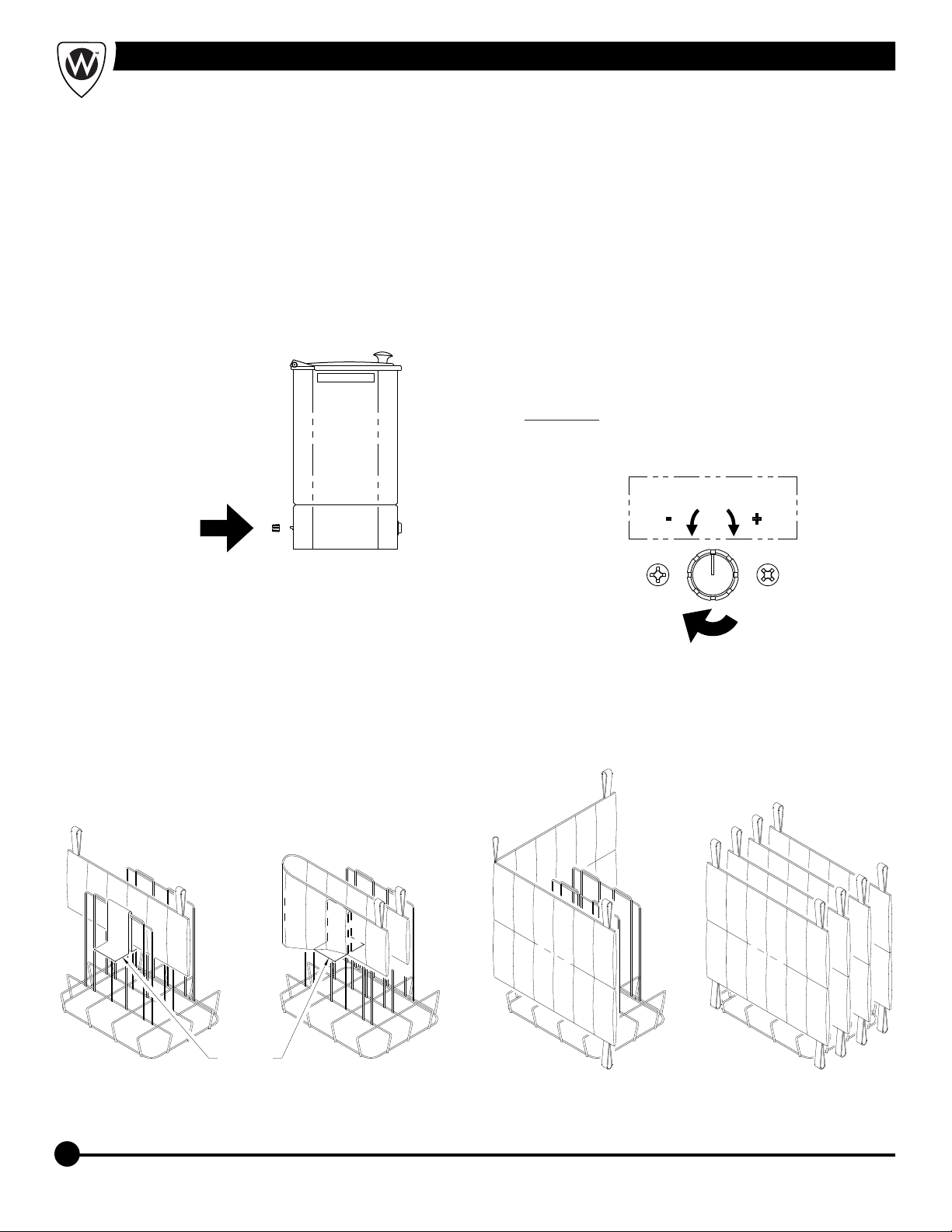
Remove all the shipping material. Remove Thermal
Packs and wire rack from inside the tank. Remove all
packaging from inside the tank, especially from under
the heating element inside the tank. Clean the unit
thoroughly before using.
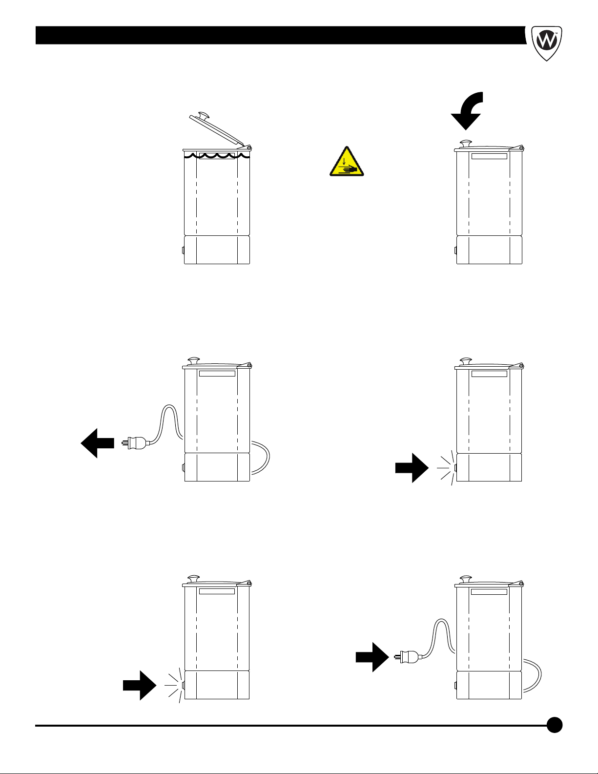
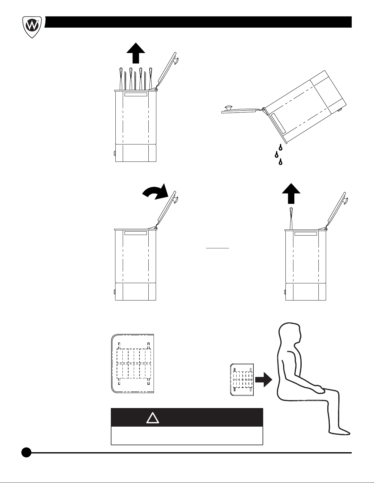
Place the Thermalator at a convenient level, such as
on a table or a scratch resistant counter top. Before
moving the Thermalator, unplug and cool the unit.
Only move the unit to empty or fill it. Always use the
handles. The unit may be hot to the touch.
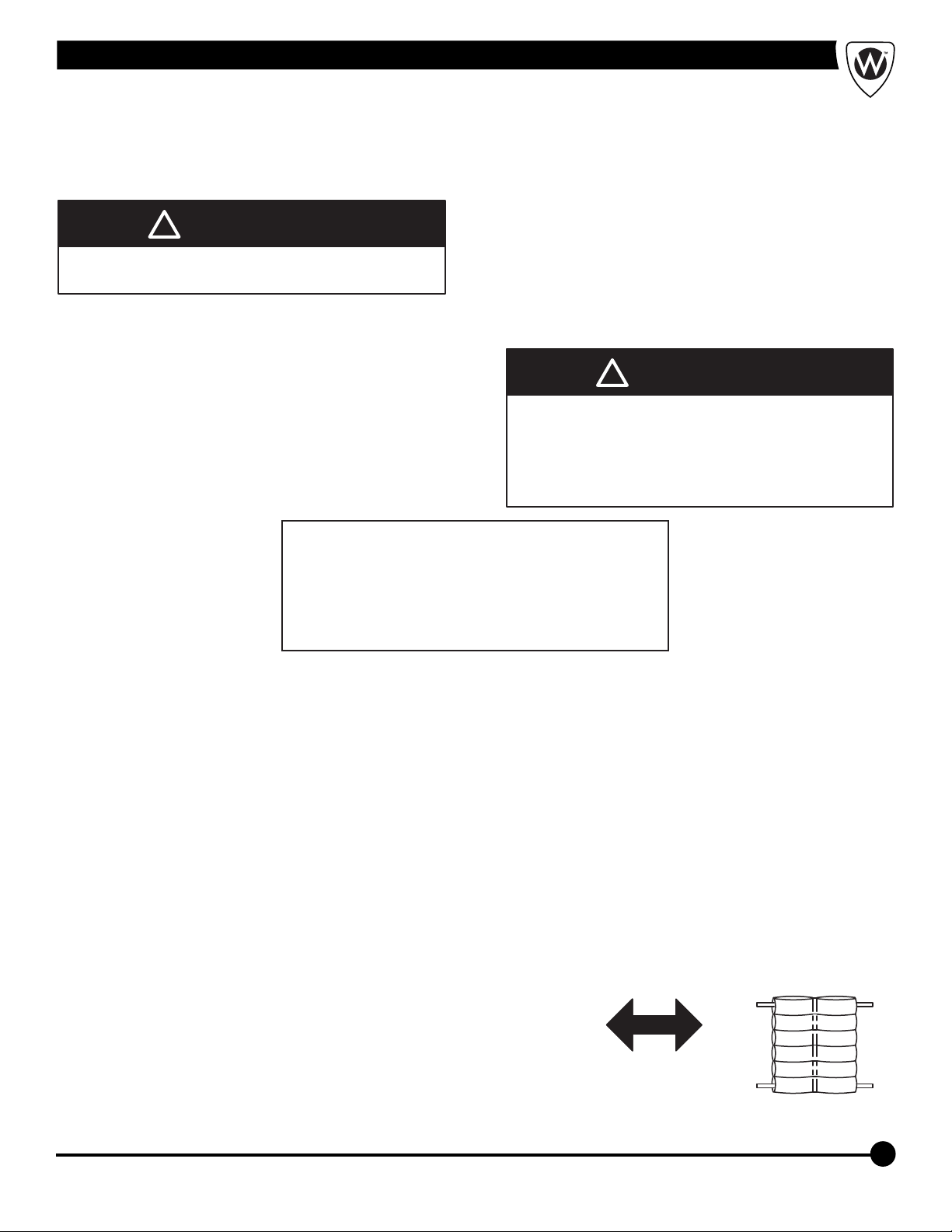
Before the first use, you must condition each Thermal
Pack.
1- Take the Thermal Pack by the corner loops - one
white and one blue or black - so the sections are
horizontal.
2- Gently shake the pack back and forth to evenly
distribute the filler material.
SETTING UP
1. Your new Thermalator includes the following:
2. Unpacking your Thermalator
3. Device Placement
Shake to distribute
the dry material
4. Pre-Soaking Thermal Packs
Instructions for Operation and Care of Stationary 4 Pack Thermalator
TRAINING
Operator trainees need to:
Ÿbe trained in occupational therapy protocols.
Ÿread and understand this manual.
Skills:
Operators using the Thermalator need a working
knowledge of occupational therapy procedures.
WARNING
!
Only trained personnel to operate the Thermalator.
Untrained operators can cause injury or be injured.
WARNING
!
OPERATOR SKILLS AND TRAINING
INSPECTING THE THERMALATOR
Inspection Checklist
Is the Thermalator free of excessive wear?
Is a properly-grounded and voltage-matched
receptacle available?
Is the outlet equipped with a functioning GFI?
Ÿ
Ÿ
Ÿ
This Whitehall product has been carefully packaged at
the factory to minimize the possibility of damage during
shipping.
— Inspect the packaging for external signs of
damage.
— Inspect the contents for damage.
If there is visible damage to the instrument upon receipt,
inform the shipping company and Whitehall immediately.
WARNING
!
Do not attempt to operate this equipment if there is
evidence of shipping damage or you suspect the unit
is damaged. Damaged equipment may present
additional hazards to you. Contact Whitehall technical
support for advice before attempting to plug in and
operate damaged equipment.
WARNING
!

WHITEHALL MANUFACTURING • P.O. BOX 3527 • City of Industry, CA 91744-0527 U.S.A
Phone (800) 782-7706 • (626) 968-6681 • Fax (626) 855-4862 • Web: www.whitehallmfg.com
4
FILLING your unit
Make sure the unit
is unplugged and
all packaging has
been removed.
Fill unit about 3/4
full with tap water.
12
Place the wire rack
inside the unit. Be
careful of the
heating element.
Put the Pre-Soaked
Thermal Packs on
the wire rack. Place
all the blue or white
tabs up.
34
Instructions for Operation and Care of Stationary 4 Pack Thermalator
3/4
3- Place the Thermal Packs in a large pan to pre soak
(use plastic, stainless steel or enamel-ware, DO
NOT use aluminum). You may use the Thermalator
for pre soaking.
Place the Thermal Pack in the pan or unit with
sections horizontal.
4- Fill the container with enough tap water to
completely cover the Thermal Packs.
5- Soak the packs for 24 hours minimum, more is
recommended.
6- Return the packs to upright position. (If the unit
was used, change the water.) The packs are now
ready for heating.
•
Turn the packs to
upright as shown

WHITEHALL MANUFACTURING • P.O. BOX 3527 • City of Industry, CA 91744-0527 U.S.A
Phone (800) 782-7706 • (626) 968-6681 • Fax (626) 855-4862 • Web: www.whitehallmfg.com
5
Plug the power cord
into an AC outlet. A
Ground Fault Circuit
Interrupter is
recommended
because it will give
additional protection
from electric shock.
7Facing the front of
the unit, turn the
power switch to the
ON position.
Indicator light
should be
illuminated.
8
EMPTYING your unit
Unplug the unit.
2
Facing the front of
the unit , turn the
power switch OFF.
The light will go out.
1
Instructions for Operation and Care of Stationary 4 Pack Thermalator
AC
Add more water, if
necessary, to cover
the Thermal Packs.
Uncovered packs
may be damaged
during heating.
Close the lid.
56
Caution! Lid can
pinch fingers.

WHITEHALL MANUFACTURING • P.O. BOX 3527 • City of Industry, CA 91744-0527 U.S.A
Phone (800) 782-7706 • (626) 968-6681 • Fax (626) 855-4862 • Web: www.whitehallmfg.com
6
USING the Thermal Pack
Wrap the pack in a
Thermal Pack Cover
or 5 to 6 layers of
terry toweling.
3Put the wrapped
pack on the area to
be treated for a
pre-set treatment
time.
4
Open the lid.
1Using tongs,
carefully remove
the Thermal Pack.
Caution: the
Thermal Pack can
cause skin burns.
2
1- For each use:
Instructions for Operation and Care of Stationary 4 Pack Thermalator
Let the water cool to
room temperature.
Remove the Thermal
Packs and the wire
rack.
3Pick up the unit by
the handles and
pour out into a sink
or floor drain.
4
WARNING
!
Use the Thermalator only as directed in this manual.
Any other use can cause injury.
WARNING
!

WHITEHALL MANUFACTURING • P.O. BOX 3527 • City of Industry, CA 91744-0527 U.S.A
Phone (800) 782-7706 • (626) 968-6681 • Fax (626) 855-4862 • Web: www.whitehallmfg.com
7
Return the pack to
the Thermalator.
If the blue tab was
up, put the white tab
up now. Work your
way from first to last,
reversing tabs each
time.
7Close the lid. The
Thermal Pack will
be reheated within
15 minutes and
ready for use.
8
Add more water, if
necessary, to cover
the Thermal Packs.
Uncovered packs
may be damaged
during heating.
1Place all the blue
tabs in the same
reference (either all
up or all down) to
start the day.
2
Remove the Thermal
Pack from the patient.
5Remove the
Thermal Pack Cover
or toweling. Hang to
dry or launder.
6
2- Daily use:
Instructions for Operation and Care of Stationary 4 Pack Thermalator
BLUE

WHITEHALL MANUFACTURING • P.O. BOX 3527 • City of Industry, CA 91744-0527 U.S.A
Phone (800) 782-7706 • (626) 968-6681 • Fax (626) 855-4862 • Web: www.whitehallmfg.com
8
3- Periodic use:
Facing the back of the
unit, find the metal
temperature stem
between the 2 screws
in the lower middle of
the unit. Attach knob.
5
Your Thermalator uses many different sizes of Thermal Packs. For Half, Cervical or Myofacial sizes, use the adapter as
shown. For Standard, Knee/Shoulder, 10" x 18" and 10" x 24" sizes, use only the wire rack.
USING the Wire Rack
Instructions for Operation and Care of Stationary 4 Pack Thermalator
Half Cervical Knee/Shoulder
10" x 18"
Standard
10" x 24"
Myofacial
Rack
Adapter
Using the knob, turn clockwise to increase the
temperature. Allow the temperature to stabilize, and
measure the water temperature with the
thermometer.
CAUTION: Sensitive thermostat - a small adjustment
changes several degrees. Temperature range of 65°F
(18°C) to 175°F (79°C) ±5°F (-15°C).
6
TEMPERATURE
The water temperature for normal operating conditions is about 165°F (74°C). The thermostat is very sensitive; even a
small adjustment can raise or lower the temperature several degrees. The thermostat has an adjustable temperature
range of 65°F (18°C) to 175°F (79°C) ±5°F (-15°C). To adjust the temperature, you need a Thermometer capable of
180° F (83° C).

WHITEHALL MANUFACTURING • P.O. BOX 3527 • City of Industry, CA 91744-0527 U.S.A
Phone (800) 782-7706 • (626) 968-6681 • Fax (626) 855-4862 • Web: www.whitehallmfg.com
•
•
•
•
•
•
•
•
•
MAINTENANCE
9
The Thermalator design is nearly maintenance-free. It
should, under most conditions, give many years of reliable
service. Clean and replace the Thermal Packs as
described below.
1. Routine Maintenance (As Needed)
See Care and Cleaning
Always keep the Thermal Packs under water. Replace
any water that has evaporated.
Destroy or discard any contaminated Thermal Packs.
•
2. Monthly Maintenance
See
Clean wire rack and insert using mild soap. Rinse
thoroughly with clean tap water. Dry with soft cloth.
Scrub your Thermal Packs with warm soap and
water.
Keep the pH (a measure of acidity of the water)
between 7.4 and 7.8 to reduce the scaling and residue
build-up.
Care and Cleaning
3. Yearly Maintenance
Replace worn out Thermal Packs. When The packs
begin to wear out, the non-toxic filler oozes through the
fabric and seams. The individual cells seem empty.
These packs don't hold the heat. Throw away worn
Thermal Packs.
Have a professional electrician thoroughly check the
following:
1 - Test for leakage current, dielectric strength, and
receptacle polarity and ground. If you need test
details, call the number listed on the back page.
2 - Check the power cord and plug. They should be
free of cuts, abrasion and other damage. Replace
the power cord assembly if it is damaged. Use only
factory authorized replacement parts.
3 - Remove the bottom cover and check all electrical
components and connections. Replace any parts
that are in questionable condition. Use only factory
authorized replacement parts.
•
•
•
STORAGE
1. Storing the Thermalator
See
Place the Thermalator upright in a dry area away from
any chemicals.
Care and Cleaning
2. Storing the Thermal Packs
Scrub your Thermal Packs with warm soap and
water.
Moist and Cold
1 - Put the moist Thermal Pack in a plastic bag.
2 - Seal the bag.
3 - Store the bag in the freezer (recommended) or
refrigerator.
Dry
1 - Air dry the Thermal Pack completely in a well
ventilated area. The filler will become hard and
caked. This doesn't hurt the bags; more Pre-
Soaking time is then necessary.
2 - Store in a dry area away from any chemicals.
•
Instructions for Operation and Care of Stationary 4 Pack Thermalator
Before attempting to clean the appliance, be sure to turn
power switch "OFF" and unplug the unit from the
electrical receptacle. If necessary, empty (drain) the
appliance by following instructions as outlined in the
"EMPTYING your unit" section.
Use a soft cloth, sponge, and/or non-abrasive cleaning
pad to clean & wipe down the appliance. DO NOT use steel
wool to clean the stainless steel surfaces since it can
cause rusting on the stainless steel surfaces.
Use mild soaps, gentle non-abrasive detergents, or mild
mixtures of ammonia to routinely clean the surfaces of the
appliance. Be sure to always rinse with clean, warm water
and wipe dry.
Bleaches or iodine should not be used, if they are, rinse
thoroughly. Never allow bleach or iodine to “soak” on the
stainless steel surface. Continued use will result in pin
holes in the stainless steel tank and cause leaking.
CARE AND CLEANING

WHITEHALL MANUFACTURING • P.O. BOX 3527 • City of Industry, CA 91744-0527 U.S.A
Phone (800) 782-7706 • (626) 968-6681 • Fax (626) 855-4862 • Web: www.whitehallmfg.com
10
REPAIR OF UNIT
It may be necessary or you may desire to return the Thermalator unit for service. In that case, we would appreciate you
contacting Whitehall Manufacturing directly. We will make arrangements for the unit to be returned to our production location.
When the unit is received by us, an estimate of repairs will be made and you will be contacted. Please- we appreciate
warranty repair or any other repair be arranged directly with Whitehall Manufacturing. If you are not satisfied with our
service, then and only then, contact your dealer.
TROUBLESHOOTING
Remove the ferrous metal
item from the unit- usually
a staple, paper clip, safety
pin, etc. Clean thoroughly.
Contact with ferrous metal
Rust in unit
Adjust the thermostatThe thermostat is set too
low
The thermostat is broken
There is a power failure
Thermal Packs too cool
Replace the thermostat
Check the circuit and turn
on the breaker
Replace the thermostatThe thermostat is broken
Thermal Packs too hot and
then too cool
Adjust the thermostat The thermostat is set too
high
The thermostat is broken
Thermal Packs too hot
Replace the thermostat
Replace the Thermal
Packs
Drain, clean and refill
The Thermal Packs are
worn out (seeping)
Too long between cleaning
Water is cloudy
Reset circuit breaker
Replace the thermostat
Replace the element
Circuit breaker is off
Thermostat is not working
Heating element is burned
out
Water doesn't get hot, even
though unit is plugged in
and switch is ON
Problem Cause Solution
Instructions for Operation and Care of Stationary 4 Pack Thermalator

WHITEHALL MANUFACTURING • P.O. BOX 3527 • City of Industry, CA 91744-0527 U.S.A
Phone (800) 782-7706 • (626) 968-6681 • Fax (626) 855-4862 • Web: www.whitehallmfg.com
11
Instructions for Operation and Care of Stationary 4 Pack Thermalator
Exploded View
28
11
16
3
4
5
6
14
9
13
15
3029
19
17
18
20
2
1
8
7
2
1
12
10
Fuse 1
Fuse 2

WHITEHALL MANUFACTURING • P.O. BOX 3527 • City of Industry, CA 91744-0527 U.S.A
Phone (800) 782-7706 • (626) 968-6681 • Fax (626) 855-4862 • Web: www.whitehallmfg.com
12
Instructions for Operation and Care of Stationary 4 Pack Thermalator
Wire rack - small 6702-040-199
6704-100-001
6704-099-001
6704-086-001
6704-098-001
6702-050-002
6503-503-199
6702-030-199
6702-060-000
0710-232-000
6505-510-000
6505-511-000
6505-500-000
6505-056-000
0710-446-000
0411-021-000
0116-011-000
6502-202-000
6502-524-000
0116-008-000
Wire connector assembly, white 6"
Thermometer Clamp Assembly
Hinge pin
Lid
Knob
Fuse holder assembly 1/4 x 1-1/4” Lg
On/Off switch (DPST w/ lamp)
Thermostat
Heating Element (120VAC/1000W) w/ washers & nuts
Power cord 13A, 125V
Thermal Overheating Sensor
Fiber washer
#10-32 x 5/16" phillips screw
#10-32 x 1/4" phillips screw
#6-32 x 3/16" phillips screw
11
10
1
26
20
22
17
27
21
2
7
16
18
6
8
25
12
19
15
23
5
3
9
24
DESCRIPTIONITEM
14
0302-010-000 #6-32 hex nut
4
6505-546-000 10A/15A 250VA Snap-in power inlet
13
6704-090-001
6704-091-001
6704-092-001
28
Wire connector assembly, white 9"
Wire connector assembly, green/yellow 6"
Wire connector assembly, white 4"
Wire connector assembly, black 9"
Wire connector assembly, black 5"
Wire connector assembly, black 6"
PART NUMBER
6702-025-199 Bottom cover
#10-32 acorn nut
6702-061-000 Handle - small
6505-508-000 Thermostat knob
29 6702-045-199 Rack adapter (stainless steel)
30
6900-136-000 Fuse 15 A, Ceramic, Time Delay, 1/4 x 1-1/4” Lg
Model T-4-S (120 VAC 60 Hz)
POWER INLET
GND
L
N
FUSE 1
HI TEMP
THERMOSTAT
OPERATING
THERMOSTAT
HEATING
ELEMENT
54
1 2
DPST
SWITCH
FUSE 2
21 22 22 2323
24 25 26 27
Protective Conductor Terminal
The protective conductor terminal symbol in the above figure
identifies the location of the bonding terminal, which is bonded to
conductive accessible parts of the enclosure for safety purposes.
Use only Time
Delay Fuse.
See Item 10
Alternating Current
Fuse Location
Symbols on labels:

WHITEHALL MANUFACTURING • P.O. BOX 3527 • City of Industry, CA 91744-0527 U.S.A
Phone (800) 782-7706 • (626) 968-6681 • Fax (626) 855-4862 • Web: www.whitehallmfg.com
13
Instructions for Operation and Care of Stationary 4 Pack Thermalator
6702-045-199
Wire rack - small 6702-040-199
6704-070-001
6704-071-001
6704-086-001
6704-083-001
6702-050-002
6503-503-199
6702-030-199
6702-060-000
0710-202-000
6505-516-000
6505-511-000
6505-501-000
Call for part #
0710-446-000
0411-021-000
0116-011-000
6502-202-000
6502-524-000
0116-008-000
Wire connector assembly, blue 6"
Thermometer Clamp Assembly
Hinge pin
Lid
Knob
Fuse 6.3 A, 5mm x 20mmCeramic, Time Delay,
On/Off switch (DPST w/ lamp)
Thermostat
Heating Element (220VAC/1000W) w/ washers & nuts
Power cord
Thermal Overheating Sensor
Fiber washer
#10-32 x 5/16" phillips screw
#10-32 x 1/4" phillips screw
#6-32 x 3/16" phillips screw
11
10
1
26
20
22
17
27
21
2
7
16
18
6
8
25
12
19
15
23
5
3
9
24
DESCRIPTIONITEM
14
0302-010-000 #6-32 hex nut
4
6505-546-000 10A/15A 250VA Snap-in power inlet
13
6704-072-001
6704-074-001
6704-073-001
28
Wire connector assembly, blue 9"
Wire connector assembly, green/yellow 6"
Wire connector assembly, blue 4"
Wire connector assembly, brown 9"
Wire connector assembly, brown 5"
PART NUMBER
6702-025-199 Bottom cover
#10-32 acorn nut
Rack adapter - Cervical (stainless steel)
6702-061-000 Handle - small
0710-230-001 Fuse holder assembly 5mm x 20mm
29
6505-508-000 Thermostat knob
30
Model ET-4-S (220 VAC 50/60 Hz)
POWER INLET
GND
L
N
FUSE 1
HI TEMP
THERMOSTAT
OPERATING
THERMOSTAT
HEATING
ELEMENT
54
1 2
DPST
SWITCH
FUSE 2
21 22 22 2323
24 25 26 27
Use only Time
Delay Fuse.
See Item 10
Protective Conductor Terminal
The protective conductor terminal symbol in the above figure
identifies the location of the bonding terminal, which is bonded to
conductive accessible parts of the enclosure for safety purposes.
Alternating Current
Fuse Location
Symbols on labels:

Instructions for Operation and Care of Stationary 4 Pack Thermalator
WHITEHALL MANUFACTURING • P.O. BOX 3527 • City of Industry, CA 91744-0527 U.S.A
Phone (800) 782-7706 • (626) 968-6681 • Fax (626) 855-4862 • Web: www.whitehallmfg.com
14
ELECTRICAL PARTS DISASSEMBLY
Thermostat
Fuses
Fuse Holder
Power Inlet
Thermal Sensor
Switch
Heating Element

Mailing Address:
P.O. Box 3527 • City of Industry, CA 91744-0527 U.S.A
Physical Address:
15125 Proctor Avenue • City of Industry, CA 91746 U.S.A
Phone 800-782-7706 • 626-968-6681
Fax 626-855-4862
Web: www.whitehallmfg.com
Any questions regarding servicing of products in Europe or the Middle East should be directed to:
Niva Medical Company • Olarinluoma 14 B, FIN-02200 Espoo, Finland
Phone 358 9 615 00 540 • Fax 358 9 615 00 545
Web www.nivamedical.fi • E-mail [email protected]
E-mail: [email protected]
Whitehall Manufacturing Company warrants that its products are free from defects in material or workmanship under
normal use and service for a period of one year from date of shipment. Whitehall's liability under this warranty shall be
discharged solely by replacement or repair of defective material, provided Whitehall is notified in writing within one
year from date of shipment, F.O.B. Industry, California.
This warranty does not cover installation or labor charges, and does not apply to materials which have been
damaged by other causes such as mishandling or improper care or abnormal use. The repair or replacement of
the defective materials shall constitute the sole remedy of the Buyer and the sole remedy of Whitehall under this
warranty. Whitehall shall not be liable under any circumstances for incidental, consequential or direct charges caused
by defects in the materials, or any delay in the repair or replacement thereof. This warranty is in lieu of all other
warranties expressed or implied. Product maintenance instructions are issued with each fixture, and disregard or non-
compliance with these instructions will constitute an abnormal use condition and void the warranty. Stainless steel
must be properly maintained after the water has been introduced into the fixture, or Whitehall's limited warranty is void.
If you have any questions or require technical assistance, please call 800-743-8219.
NOTICE TO KEEP ORIGINAL PACKAGING- Regarding warranty claims: customer must retain original packaging
for one year upon receipt of product. If packaging is discarded, it is the customer's responsibility to provide adequate
packaging. Any shipping claims that are a direct result of customer-provided packaging materials will be handled by
the shipper.
MANUFACTURER'S WARRANTY
Member of
0537
EC REP
This manual suits for next models
1
Table of contents
Other Whitehall Manufacturing Medical Equipment manuals
Popular Medical Equipment manuals by other brands

Orliman
Orliman IC-40 INSTRUCTIONS FOR USE AND PRESERVATION

Thuasne
Thuasne Sleeq Max TLSO Instructions for use

Gaymar
Gaymar T/PUMP TP500 Service manual

Tecno-gaz
Tecno-gaz Multisteril Fast Instructions for use

HoMedics
HoMedics CMS50D1A Instructions for use

DeVilbiss Healthcare
DeVilbiss Healthcare Drive Ambience user manual