Wickes PHG200B User manual

PHG200B
223737
HOT AIR GUN
2000W

CONTENTS
GENERAL POWER TOOL SAFETY WARNINGS 3
3
4
4
5
5
6
9
9
10
11
ADDITIONAL SAFETY INSTRUCTIONS FOR YOUR HEAT GUN
COMPONENT LIST
ACCESSORIES
SYMBOLS
TECHNICAL DATA
OPERATING INSTRUCTIONS
PLUG REPLACEMENT (ONLY FOR REWIRABLE PLUG OF UK & IRELAND)
MAINTENANCE
DECLARATION OF CONFORMITY
TROUBLESHOOTING

3
WARNING! Read all safety warnings and all instructions. Failure to follow the warnings and instructions
may result in electric shock, re and/or serious injury.
Save all warnings and instructions for future reference.
- This appliance is not intended for use by persons (including children) with reduced physical, sensory or mental
capabilities, or lack of experience and knowledge, unless they have been given supervision or instruction
concerning use of the appliance by a person responsible for their safety.
- Children should be supervised to ensure that they do not play with the appliance.
If the supply cord is damaged, it must be replaced by the manufacturer, its service agent or similarly qualied
persons in order to avoid a hazard.
ADDITIONAL SAFETY INSTRUCTIONS FOR YOUR HEAT GUN
GENERAL POWER TOOL SAFETY WARNINGS
1. A re may result if the appliance is not used with care, therefore
- be careful when using the hot air gun where there are combustible materials;
- do not apply to the same place for a long time;
- do not use in an explosive atmosphere;
- be aware that heat may be conducted to combustible materials that are out of sight;
- place the appliance on a non-combustible surface after use and allow it to cool down before storage;
- do not leave the hot air gun unattended when it is switched on.

4
COMPONENT LIST
Nozzle
Heat protection
Main body
Cool air inlet
On/off switch / Air ow and temperature regulator
AC Mains Lead
Scraper 1
Glass protection nozzle 1
Flat nozzle 1
Hook nozzle 1
Concentration nozzle 1
We recommend that you purchase your accessories from the same store that sold you the tool. Use good quality
accessories marked with a well-known brand name. Choose the type according to the work you intend to undertake.
Refer to the accessory packaging for further details. Store personnel can assist you and offer advice.
Scraper
Concentration nozzle
Glass protection nozzle
Hook nozzle
Flat nozzle
1
3
5
2
4
6
11
7
9
8
10
ACCESSORIES
3
124
5
6
7
8
10
9
11

5
SYMBOLS
Read the manual
Warning
Wear ear protection
Wear eye protection
TECHNICAL DATA
Wear dust mask
Double insulated
Waste electrical products must not be
disposed of with household waste. Please
recycle where facilities exist. Check with
your local authorities or retailer for recycling
advice.
Rated Voltage 230-240V~50Hz
Power 2000W
Temperature/Flow rate I =70OC, 500L/min
II =350OC 300L/min
III= 550OC 500L/min
Machine weight 0.6kg
Protection class /II

6
OPERATING INSTRUCTIONS
NOTE: Before using the tool, read the instruction book carefully.
Intended Use
The unit is intended for the forming and welding of plastic, removal of paint and warming of heat-shrinkable tubing. It is
also suitable for soldering and tinning, loosening of adhesive joints and the defrosting of water lines.
BEFORE USING THE TOOL
Before starting the job it is advisable to test the workpiece for the ideal temperature to use. The description below gives
an indication of the likely heat settings required but always start with the low heat setting.
The distance between the nozzle and the workpiece will vary according to the material being worked on but this should
always be at least 50mm (2 inches) or more on either heat setting.
All applications, with the exception of removing paint from the window frames, can be performed without using a nozzle;
however for best results nozzles are recommended.
PUTTING INTO OPERATION
1. SWITCHING ON/OFF
Switching on:
To put into operation, slide the switch (5) to position 1, 2 or 3.
Switching off:
To switch off, slide the on/off switch (5) to the stop at position 0.
After working for a long time with a high temperature, allow the gun to cool by running in the lowest temperature setting
before switching off.
2. THERMO-PROTECTION SWITCH-OFF
When the heater is overloaded (e.g. as a result of restricted air ow), the unit switches it off automatically, however, the
blower continues to run. When the unit has cooled to operating temperature, the heater is switched on again.
3. SETTING THE AIR FLOW AND TEMPERATURE
The switch (5) can be set to three blower steps. Suitable air ow and temperature combinations can be selected
according to the applications.
I =70oC, 500L/min
2 =350oC 300L/min
3= 550oC 500L/min
The warm air setting 1 (70°) is suitable for the drying of paint. It is also suitable for cooling the unit before storage.
The air setting 2 is suitable for bending plastic and heating shrinking plastic.
The air setting 3 is suitable for stripping paint and defrosting pipes.
4. NOZZLES
The kit is supplied with 4 different shaped nozzles, which can be used as follows:

7
This nozzle directs a concentrated heat ow to the
workpiece. It is ideal for use when removing paint
in awkward corners, crevices, mouldings, beading,
architraves or whenever precise paint removal is
required.
1) CONCENTRATION NOZZLE (See Fig. A)
This nozzle directs a long narrow heat pattern to the
workpiece, and is ideal for removing paint or varnish
from large at surfaces such as skirting boards, doors,
stairs etc. It should be used in conjunction with a at
scraper. Vinyl tiles can be removed by softening the tile
and adhesive.
This nozzle deects the heat away from glass or other
fragile areas and back onto the workpiece.
This nozzle disperses the heat ow evenly around the
whole workpiece. It is ideal for defrosting frozen pipes,
soldering pipe work, bending plastics and heat-shrinking
electrical parts.
2) FLAT NOZZLE
(See Fig. B)
3) GLASS PROTECTION NOZZLE (See Fig. C)
4) HOOK NOZZLE (See Fig. D)
Fig. B
Fig. C
Fig. D
Fig. A

8
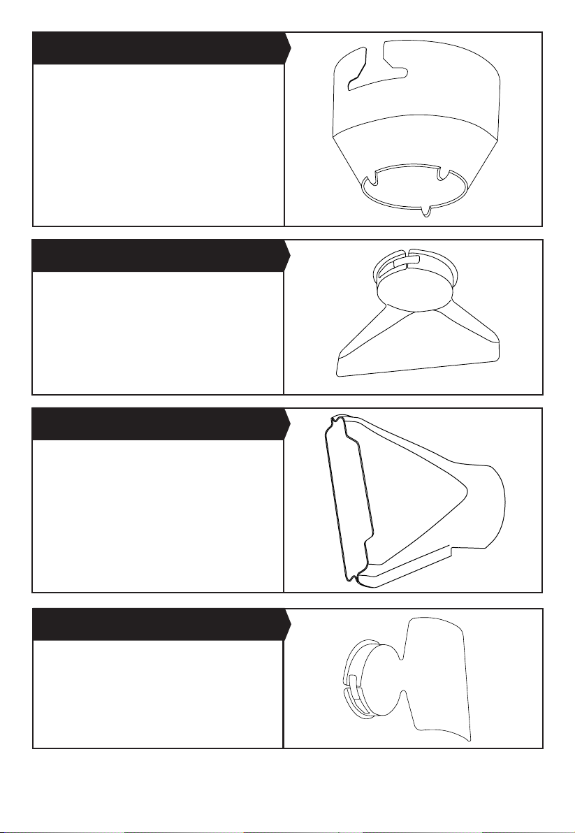
Take the handle from the set, remove the nut from the
end, and t the triangle blade in place by retting and
tightening the nut. The triangular scraper is ideal for
stripping paint from at wooden surface and edges.
Remember to clean the blade after use with wire wool
and lightly oil before storing.
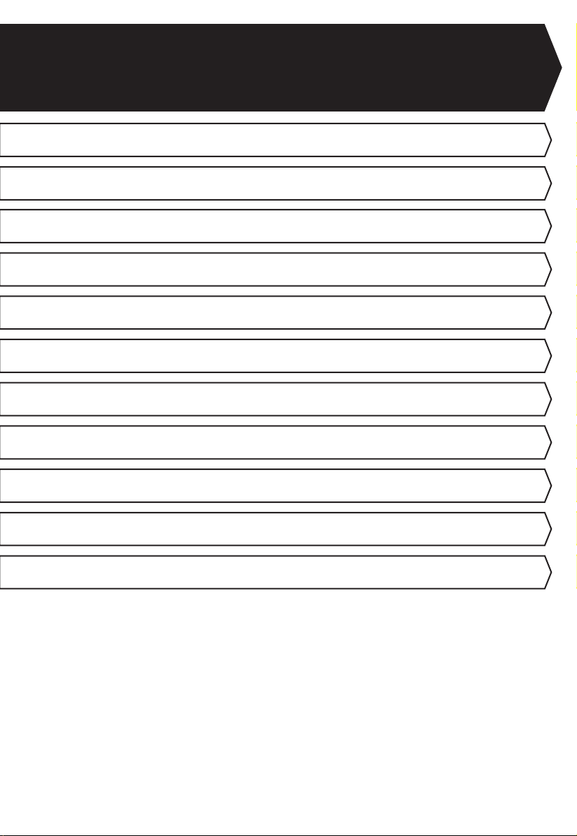
Choose the required nozzle and t onto the heat outlet.
Select the scraper required. Hold the gun with the nozzle
approximately 50mm (2 inches) from the surface of the
paintwork and starting with the lower heat setting, move
it slowly backwards and forwards until the paint blisters
and bubbles. Immediately remove the paint with the
scraper . Aim to heat the paint just ahead of the scraper
so that you can develop a continuous action. Do not heat
the paint for too long, as this will burn the paint making it
difcult to remove.
Most stickers can also be removed from paintwork by
using the heat to soften the adhesive. Be careful not to
direct the heat for too long if you are trying just to remove
the stickers, as this will blister the paint.
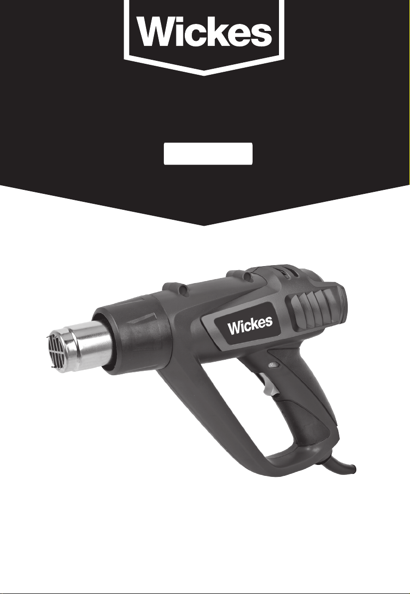
Always use the glass protection nozzle. Ensure you have the nozzle facing the correct way to deect the heat away from
the glass before you switch on. Rotate the gun or nozzle 900 as you move to horizontal or vertical bead. Allow nozzle to
cool before attempting to turn it. Paint can be removed from prole surfaces by using scraper and/or a soft wire brush.
WARNING: Glass can break easily.
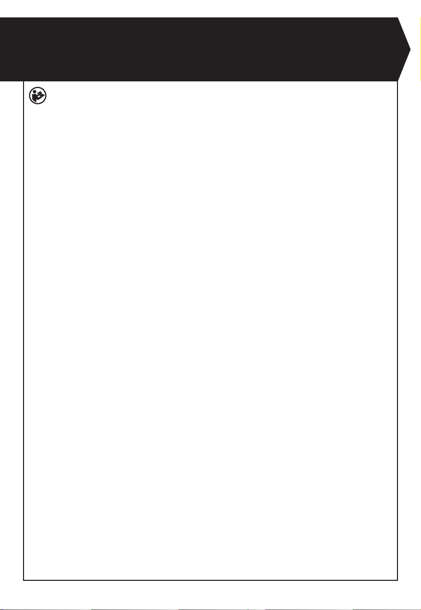
Choose the Hook nozzle and t over the heat outlet. Always heat from one or other end of the frozen portion, not from
the middle.
WARNING: Do not attempt to defrost PVC pipes. Always check that it is a water pipe and not a gas pipe. Do not
heat a gas pipe.
5) SCRAPER (See Fig. E)
5. REMOVING PAINT (See Fig. F)
6. REMOVING PAINT FROM WINDOW FRAMES
7. DEFROSTING FROZEN PIPES
Fig. E
Fig. F

9
8. SHRINK SLEEVING ELECTRICAL CABLES
9. BENDING PLASTIC TUBE
Choose the Hook nozzle and t over heat outlet. Select a heat-shrinkable sleeve with a diameter matching that of the
workpiece. Evenly heat the sleeve.
Choose the Hook nozzle and t over heat outlet. Turn the gun upside down and place on its clip stand so that it is resting
on a secure bench with the nozzle pointing upwards, see picture. To avoid buckling or kinking the tube, ll the tube with
dry sand and seal at both ends. Heat the tube evenly by moving from side to side and bend to required shape.
WARNING: Protect hands from heat.
Remove the plug from the socket and allow to cool before carrying out any adjustment or maintenance.
There are no user serviceable parts in your power tool. Never use water or chemical cleaners to clean your power tool.
Wipe clean with a dry cloth. Always store your power tool in a dry place. Keep the motor ventilation slots clean. Keep all
working controls free of dust. Occasionally you may see sparks through the ventilation slots. This is normal and will not
damage your power tool.
If the supply cord is damaged, it must be replaced by the manufacturer, its service agent or similarly qualied persons in
order to avoid a hazard.
1. If your heat gun will not operate, check that it is plugged in, switched on and the fuse is intact.
2.
If the gun has over-heated and is blowing only cool air, direct the ow away from your workpiece until the heat is restored.
3. If any fault cannot be rectied, please contact the helpline on the back of this booklet.
MAINTENANCE
TROUBLESHOOTING
This product has been marked with a symbol relating to removing electric and electronic waste. This means
that this product shall not be discarded with household waste but that it shall be returned to a collection system
which conforms to the European Directive 2002/96/CE. It will then be recycled or dismantled in order to reduce
the impact on the environment. Electric and electronic equipment can be hazardous for the environment and for
human health since they contain hazardous substances
ENVIRONMENTAL PROTECTION

10
PLUG REPLACEMENT (ONLY FOR REWIRABLE PLUG OF UK &
IRELAND)
If you need to replace the tted plug then follow the instructions below.
IMPORTANT
The wires in the mains lead are colored in accordance with the following code:
Blue = Neutral
Brown = Live
As the colors of the wires in the mains lead of this appliance may not correspond with the colored markings identifying
the terminals in your plug, proceed as follows. The wire which is colored blue must be connected to the terminal which is
marked with N. The wire which is colored brown must be connected to the terminal which is marked with L.
Warning!
Never connect live or neutral wires to the earth terminal of the plug. Only t an approved 13A BS1363/A plug and the correct
rated fuse.
Note: If a moulded plug is tted and has to be removed take great care in disposing of the plug and severed cable, it must
be destroyed to prevent engaging into a socket.
13 Amp fuse approved
to BS1362
Connect
Blue to N
(neutral)
Outer sleeve
rmly clamped
Brown L(live)
Cable grip

11
DECLARATION OF CONFORMITY
We,
Wickes Building Supplies Limited
Declare that this product: HOT AIR GUN
Description and SKU code: 223737
Complies with the following Directives and Regulations:
2014/30/EU, Electromagnetic Compatibility Directive
2011/65/EU & (EU)2015/863, Restriction of Hazardous Substances Directive
2014/35/EU, Low Voltage Directive
and conforms to the following standards:
Standards specic to this product:
EN 60335-1
EN 60335-2-45
EN 55014-1
EN 55014-2
EN 61000-3-2
EN 61000-3-3
EN 62233
28th January, 2021
Philip Ansell
Category Technical Manager
Wickes
Vision House
19 Colonial Way
Watford
WD24 4JL”

Customer Helpline 0345 2005409
This manual suits for next models
1
Table of contents
Other Wickes Power Tools manuals
Popular Power Tools manuals by other brands

wurth
wurth BS 14-A Compact operating instructions

Bosch
Bosch GSS 230 AVE Original instructions

Westfalia
Westfalia 66 33 28 instruction manual

Parkside
Parkside PAR 10.8 A1 translation of original operation manual

Rockwell
Rockwell RS2323 ShopSeries user guide

Black & Decker
Black & Decker 5022K instruction manual