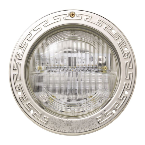
Wiedamark LPL-6 Series User manual

ITEM NO.:
LPL-6 Series
ITEM NO.:
Page 1 / 4
LED POOL LIGHT
This product is mainly used for swimming pool,underwater fixture.With friendly and
convenient operation,it can offer magic effects in water and ground.
INSTRUCTION OF LED POOL LIGHT/LPL
LPL-6-18P LPL-6-36P
B. Working mode
B-1. DMX512 mode (signal from DMX console)
B-2. Built-in mode
B-3. Master/Slave mode Mode(Master=001,Slave≠001)
Press the MODE button to the interface as Figure 3, the address(A,B,C,D,E,F )display on the LCD screen
are corresponding to the output port on the controller (1 # 2 # 3 # 4 # 5 # 6 # ).Press SET button to choose
different output port;Press the UP and Down button to the desired address,each port can set as digits less
than 512.
MODE SET UP DOWN
1# 2# 3# 4# 6#5#
A002
D011
B005
E014
C008
F017
C. Function & Setup
C-1.DMX Channel instruction-3 Channels available as sheet:
***Enter or quit DMX mode automatically once detecting valid signal!!!
Data Function Data Function Data Function
CHANNEL 1 CHANNEL 2 CHANNEL 3
0~255 0~255
Brightness of Red 0~255
Brightness of Green Brightness of Blue
C-2. DMX Address Setting
A-1. Structure
A. Specification
Model No.
LED Color
LED
Quantity
Power
Consumption
Beam
Angle
Size
Weight
√
LPL-6-18P
R, G, B
18
23 WATTS
ooo
10 /20 /45
Ø170xH180mm
2.6kg±5%
LPL-6-36P
R, G, B
36
45 WATTS
ooo
10 /20 /45
Ø210xH190mm
4.4kg±5%
Materials of Shell: Aluminum alloy/6063
Rotary angle: 150°
Input Voltage: 24V DC
Protecting Rating: IP68
Operating Temperature: -20℃~40℃
A-1. Model Configuration Table

D.Photometrics
D-1. Cadela distribution
D-2.Illuminance at a distance
LPL-6-36P-240V-W-15° LPL-6-36P-240V-W-45°
LPL-6-36P-240V-WW-15° LPL-6-36P-240V-WW-45°
C-3 .Program Menu
Welcome To Use
CTR-RGB-BOX V2.0
29 Pingpong
00 BlackOut
01 Static Red
Brightness:255
02 Static Green
Brightness:255
03 Static Yellow
Brightness:255
04 Static Blue
Brightness:255
05 Static Purple
Brightness:255
06 Static Cyan
Brightness:255
07 Static White
Brightness:255
08 Dimmer
R255 G255 B255
09 Color change
Speed: 100
System Time Set
2001-00-01 18:43
ON ---> OFF
18:14--->23:04
UP or DOWN
MODE
10 Color Flash
Speed: 100
11 Red Fade
Speed: 100
12 Green Fade
Speed: 100
13 Yellow Fade
Speed: 100
14 Blue Fade
Speed: 100
15 Purple Fade
Speed: 100
16 Cyan Fade
Speed: 100
17 White Fade
Speed: 100
18 Color Fade1
Speed: 100
19 Color Fade2
Speed: 100
20 Left Flow
Speed: 100
21 Right Flow
Speed: 100
22 Bidir-Flow
Speed: 100
23 Side->Middle
Speed: 100
24 Middle->Side
Speed: 100
25 Side<->Middle
Speed: 100
26 Left Stack
Speed: 100
27 Right Stack
Speed: 100
28 Bidir-Stack
Speed: 100
29 Pingpong
Speed: 100
Setup
Speed/Brightness/Cycle can be
adjusted with each function!
***Speed range: 0~100(fastest)
***Brightness range: 0~255(brightest)
***Cycle range: 1~16
System Setting
DMX Address # x
Setup
Setup Quantity: Define the quantity loaded by controller
Start Addr: Define the starting DMX address of the 1st fixture
Setup
YEAR-2001
MONTH-00
DAY-01
HOUR-18
MINUTE-43
30 Rainbow Left
Speed: 100
31 Rainbow Right
Speed: 100
32 AutoRun Mode
Cycle: 16
On-Controller start to work
OFF-Controller stop to work
Use 【UP】or 【DOWN】to adjust all active parameters!
DMX address of 1#~6# fixtures is not required to be of serial,
under built-in programs/functions.
ITEM NO.:
LPL-6 Series
ITEM NO.:
Page 1 / 4
LED POOL LIGHT

E.Dimension drawing
Ø170
180
190
Ø210
LPL-6-18P LPL-6-36P
F.Installation
LPL-6-36P-240V-W-15° LPL-6-36P-240V-W-45°
LPL-6-36P-240V-WW-15° LPL-6-36P-240V-WW-45°
Fix the brackets via M6 tapping screw,mounting size as below:
ITEM NO.:
LPL-6 Series
ITEM NO.:
Page 1 / 4
LED POOL LIGHT
3X∅6.5
∅170

1#
2#
3#
4#
5#
6#
CTR-RGB-BOX 2
DMX Console
DMX In
CTR-RGB-BOX 1
DMX Out
DMX Out
V+ BGR
Outlet
Power Plug
Power Plug
G. Connection
Firstly, take apart the PC cover, remove the terminals, wring
the output terminal as shown in Figure 3, then plug the ter-
minal on the pins (original position), separate the bonding
clamp for compressing the wire and lock the PC cover. We
generally use 4 colors(red, green, blue, black) in our 4 wires
and 3 circuits products.
Wiring corresponding follows:
Black wire ----------- V+
Red wire ----------- R
Green wire ----------- G
Blue wire ----------- B
***Please refer to actual definition of color of cable in different fixtures.
V+
B
G
R
PC Cover
Terminals
Wire Clamp
Pins
Terminals
CTR-RGB-BOX
Caution:
1. Do not plug them into power when the
product is still in package;
2. Don't use anything to cover the fixture
during application;
3. Don't use this product in close environment;
4. If this product appears to be damaged, do not
attempt any repair, please contact your dealer.
Make sure the ground connection well
avoid electric shock, due to metal housing.
Neglect on actio of the above treatment
will lead to failure of waterproof and proper
working of the lights!!
ITEM NO.:
LPL-6 Series
ITEM NO.:
Page 1 / 4
LED POOL LIGHT
This manual suits for next models
2
Popular Swimming Pool Lighting manuals by other brands
Seamaid
Seamaid 501160 installation guide

Seamaid
Seamaid LedInPool 500866 Usage & Maintenance Manual

INNOVAPLAS
INNOVAPLAS 9080 manual

Astral Pool
Astral Pool LUMIPLUS NF Series Installation and maintenance manual

Halco
Halco ProLED FLCN Installation and operation guide

Aqua Quip
Aqua Quip QC Series Installation instructions & owner's manual