Wieland SLX-COLM Series User manual
Montageanleitung (Original)
SLX/SLD-COLM
Wieland Electric GmbH
Brennerstraße 10-14
96052 Bamberg/Germany
Ph. +49 (0) 951 9324-999
Fax +49 (0) 951 9324-198
Internet: www.wieland-electric.com
Email: safety@wieland
-
electric.com
MOUNTING INSTRUCTIONS MONTAGEANWEISUNG DE MOUNTING INSTRUCTIONS EN
SPIEGELSÄULE SLD-COLM MIT EINZELSPIEGELN UND SLX-
COLM DURCHGEHENDEM SPIEGEL MIRROR COLUMN SLD-COLM WITH INDIVIDUAL
MIRRORS AND SLX-COLM CONTINUOUS MIRROR
© Wieland Electric GmbH BA000919 2013/05 Doc. # 700172
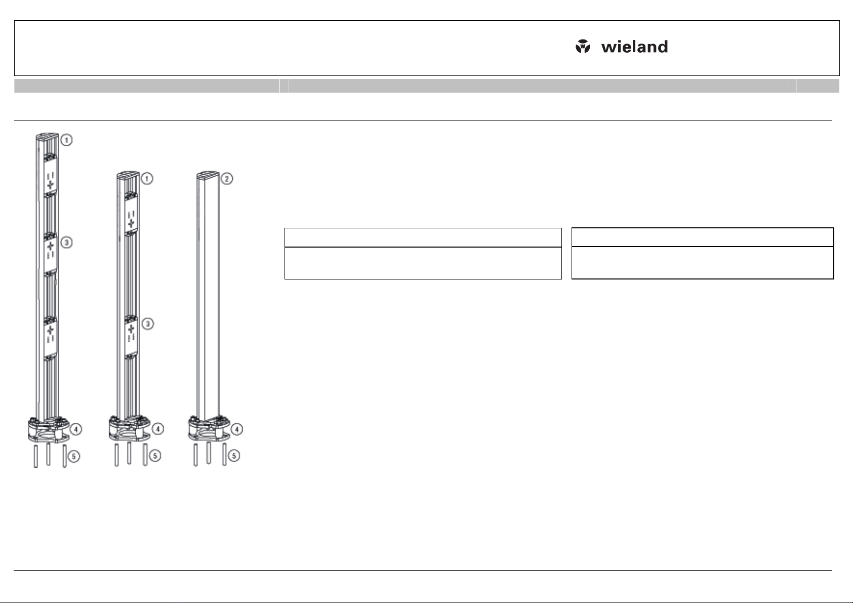
SLD-COLM3-
1360
SLD-COLM-1060
SLX-COLM-1300
SLD-COLM3-yy0a*
SLX-COLM-yy00*
SLD-MIR
SLX-COLM-BASE
Fix-Anker
Bohrschablone
*
yy0a/yy00 Höhe
HINWEIS:
Befolgen Sie sorgfältig alle Hinweise zum Sicherheits-Sensor in
der Original Betriebsanleitung auf der beiliegenden CD-ROM.
Montageschritte (Step):
1. Säule am Boden befestigen
2. Säule ausrichten
3. Sicherheits-Sensor ausrichten und in Betrieb nehmen
4. Spiegel ausrichten
5. Empfänger des Sicherheits-Sensors ausrichten
6. Checkliste – Vor der ersten Inbetriebnahme bearbeiten (siehe
Original Betriebsanleitung des Sicherheits-Sensors)
Erforderliche Werkzeuge:
•Inbusschlüssel-Satz
•Sechskantschlüssel-Satz
•Wasserwaage
•Bohrhammer mit 10 mm Betonbohrer
•Hammer
•Torxschraubendreher T15
SLD-COLM3-yy0a*
SLX-COLM-yy00*
SLD-MIR
SLX-COLM-BASE
Fix-Anker
Drilling template
*
yy0a/yy00 height
NOTE:
Carefully follow all notices regarding the safety sensor
in the original operating instructions on the enclosed CD-ROM.
Mounting steps:
1. Fasten the column on the floor
2. Align column
3. Align and start up safety sensor
4. Align mirror
5. Align receiver of the safety sensor
6. Edit Checklist – before the initial start-up (see original
operating instructions of the safety sensor)
Necessary tools:
•Allen key set
•Hexagon wrench set
•Spirit level
•Hammer drill with 10 mm concrete bit
•Hammer
•T15 Torx screwdriver
Montageanleitung (Original)
SLX/SLD-COLM
Wieland Electric GmbH
Brennerstraße 10-14
96052 Bamberg/Germany
Ph. +49 (0) 951 9324-999
Fax +49 (0) 951 9324-198
Internet: www.wieland-electric.com
Email: safety@wieland
-
electric.com
MOUNTING INSTRUCTIONS MONTAGEANWEISUNG DE MOUNTING INSTRUCTIONS EN
SPIEGELSÄULE SLD-COLM MIT EINZELSPIEGELN UND SLX-
COLM DURCHGEHENDEM SPIEGEL MIRROR COLUMN SLD-COLM WITH INDIVIDUAL
MIRRORS AND SLX-COLM CONTINUOUS MIRROR
© Wieland Electric GmbH BA000919 2013/05 Doc. # 700172
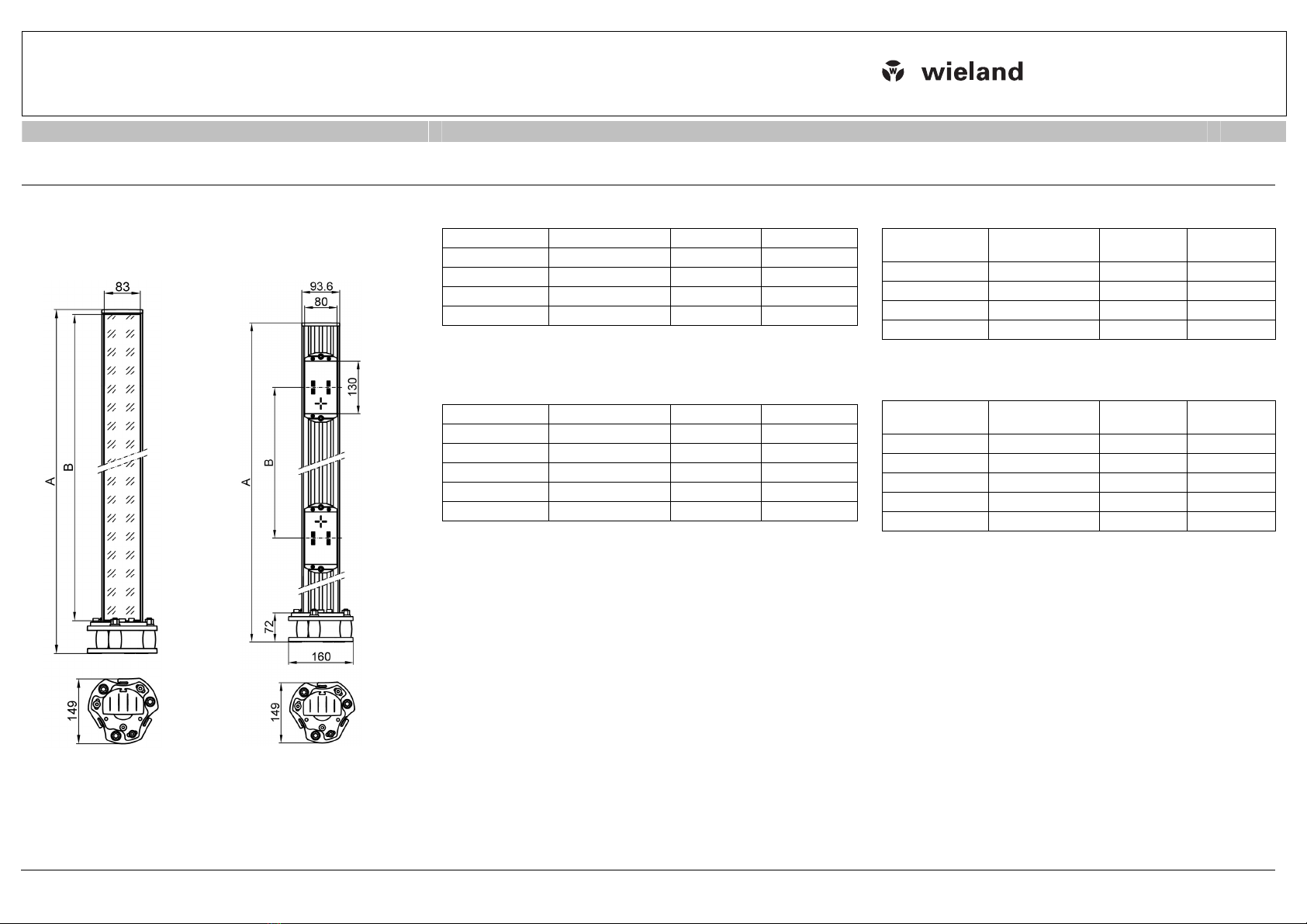
Maßzeichnung /
dimensional drawing,
durchgehender Spiegel /
continuos mirror
Maßzeichnung /
dimensional drawing,
Einzelspiegel / individual
mirror
Maßtabelle, durchgehender Spiegel /
Bestellhinweise
Artikel-Nr. Artikel Maß A [mm] Maß B [mm]
R1.594.1000.0 SLX-COLM-1000 1060 970
R1.594.1300.0 SLX-COLM-1300 1360 1270
R1.594.1600.0 SLX-COLM-1600 1660 1570
R1.594.1900.0 SLX-COLM-1900 1960 1870
Maßtabelle, Einzelspiegel /
Bestellhinweise
Artikel-Nr. Artikel Maß A [mm] Maß B [mm]
R1.604.0900.0 SLD-COLM2-0900 960 500
R1.604.1060.0 SLD-COLM2-1060 1060 500
R1.604.1363.0 SLD-COLM3-1360 1360 400
R1.604.1364.0 SLD-COLM4-1360 1360 300
R1.604.0001.0 SLD-MIR
Measurement table, continuos mirror /
Ordering information
Article No. Article Measurement
A [mm] Measurement
B [mm]
R1.594.1000.0 SLX-COLM-1000 1060 970
R1.594.1300.0 SLX-COLM-1300 1360 1270
R1.594.1600.0 SLX-COLM-1600 1660 1570
R1.594.1900.0 SLX-COLM-1900 1960 1870
Measurement table, individual mirrors /
Ordering information
Article No. Article Measurement
A [mm] Measurement
B [mm]
R1.604.0900.0 SLD-COLM2-0900 960 500
R1.604.1060.0 SLD-COLM2-1060 1060 500
R1.604.1363.0 SLD-COLM3-1360 1360 400
R1.604.1364.0 SLD-COLM4-1360 1360 300
R1.604.0001.0 SLD-MIR

Montageanleitung (Original)
SLX/SLD-COLM
Wieland Electric GmbH
Brennerstraße 10-14
96052 Bamberg/Germany
Ph. +49 (0) 951 9324-999
Fax +49 (0) 951 9324-198
Internet: www.wieland-electric.com
Email: safety@wieland
-
electric.com
MOUNTING INSTRUCTIONS MONTAGEANWEISUNG DE MOUNTING INSTRUCTIONS EN
SPIEGELSÄULE SLD-COLM MIT EINZELSPIEGELN UND SLX-
COLM DURCHGEHENDEM SPIEGEL MIRROR COLUMN SLD-COLM WITH INDIVIDUAL
MIRRORS AND SLX-COLM CONTINUOUS MIRROR
© Wieland Electric GmbH BA000919 2013/05 Doc. # 700172
Step 1
Arbeitsschritte:
1. Säule am Boden befestigen
Bestimmen Sie den Befestigungsmittelpunkt der Säule
an
hand der Bodenplatte und markieren Sie diesen auf dem
Boden.
Achten Sie darauf, dass der Winkel der Spiegelsäule zu
den ankommenden Strahlen gleich groß ist wie der Winkel
zu den abgehenden Strahlen!
Setzen Sie die Bohrschablone auf den Mittelpunkt auf,
richten Sie sie aus und markieren Sie die Bohrungen.
Bohren Sie die Befestigungslöcher nach Anweisung und
setzen Sie die Bodenanker ein.
Setzen Sie die Säulen auf und schrauben Sie diese fest.
Work steps:
1. Fasten the column on the floor
Use the base plate to determine the mounting mid-
point of the column and make a mark on the floor.
Make sure that the angle of the mirror column to the
incoming beams is the same as that of the angle to
the outgoing beams!
Set the drilling template on the center point, align it
and mark the bore holes.
Drill the fixing holes according to instructions and
insert the floor anchors.
Set the columns up and screw them on firmly.
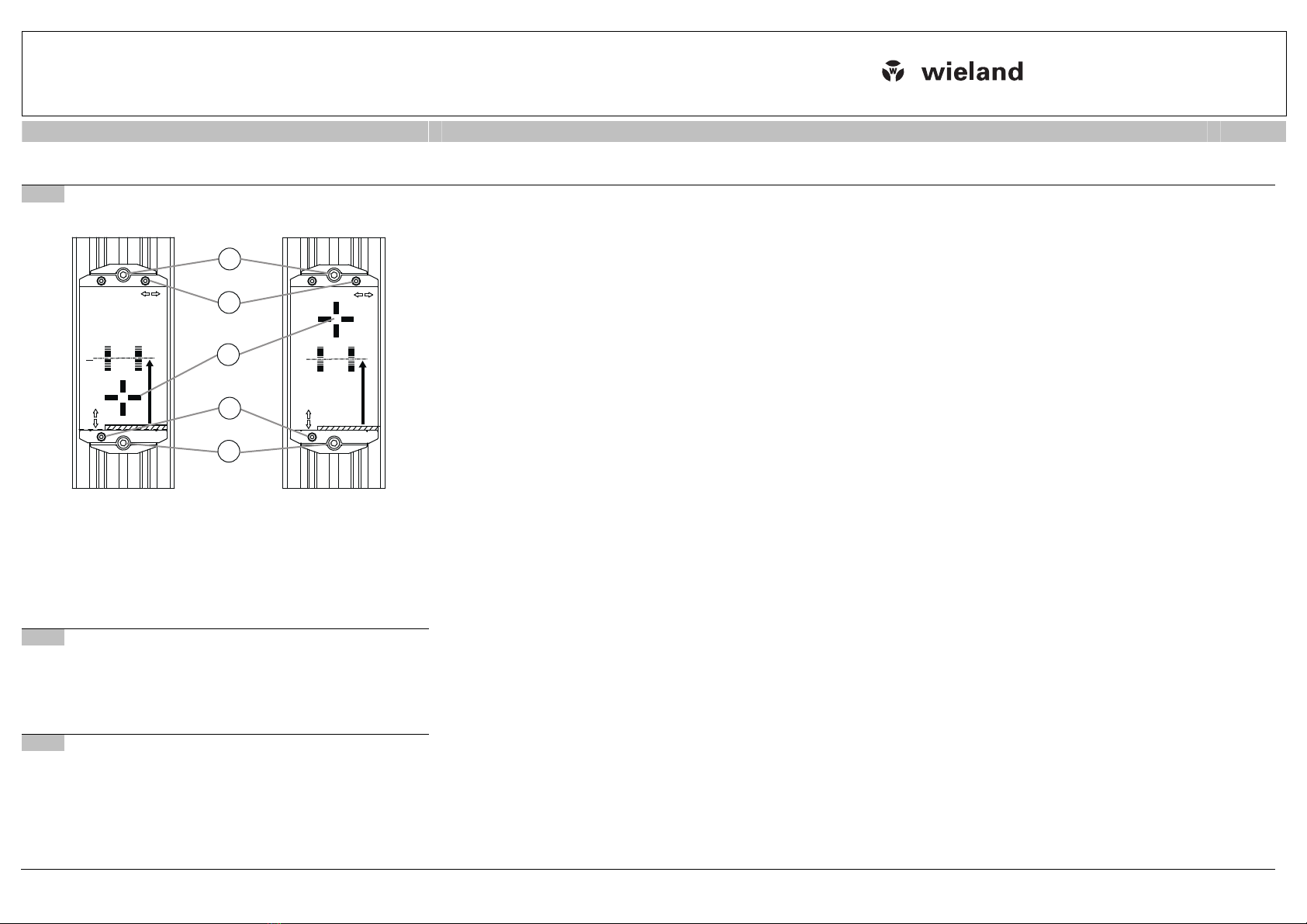
Step 2
2. Säule ausrichten
Justieren Sie die Säule mit Hilfe der Libelle (1) grob.
Justieren Sie die Säule an den Justageschrauben (2) mit
Hilfe der Wasserwaage in eine senkrechte Position.
Lösen Sie die Inbusschrauben (3) und justieren Sie die
Säule axial.
Achten Sie darauf, dass der Winkel der Spiegelsäule zu
den ankommenden Strahlen gleich groß ist wie der Winkel
zu den abgehenden Strahlen!
Libelle
Justageschrauben
Inbusschrauben
Bohrungen für Bodenanker, Ø 10 mm
Kunststoff-Federelement mit selbsttätiger Rückstellung
2. Align column
Roughly align the column using the spirit level (1).
Align the column to the alignment screws (2) in a
vertical position using the spirit level.
Loosen the Allen screws (3) and align the column
axially.
Make sure that the angle of the mirror columns to the
incoming beams is the same as that of the angle to
the outgoing beams!
Spirit level
Alignment screws
Allen screws
Bore holes for floor anchors, Ø 10 mm
Plastic spring element with automatic resetting

Montageanleitung (Original)
SLX/SLD-COLM
Wieland Electric GmbH
Brennerstraße 10-14
96052 Bamberg/Germany
Ph. +49 (0) 951 9324-999
Fax +49 (0) 951 9324-198
Internet: www.wieland-electric.com
Email: safety@wieland
-
electric.com
MOUNTING INSTRUCTIONS MONTAGEANWEISUNG DE MOUNTING INSTRUCTIONS EN
SPIEGELSÄULE SLD-COLM MIT EINZELSPIEGELN UND SLX-
COLM DURCHGEHENDEM SPIEGEL MIRROR COLUMN SLD-COLM WITH INDIVIDUAL
MIRRORS AND SLX-COLM CONTINUOUS MIRROR
© Wieland Electric GmbH BA000919 2013/05 Doc. # 700172
Step 3
3. Sicherheits-Sensor ausrichten und in Betrieb nehmen
Stellen Sie den elektrischen Anschluss her. Verbinden Sie
hierzu die Anschlussleitung (Maschinen-Interface) mit dem
Sicherheits-Sensor und schließen Sie diese wie in der
Original Betriebsanleitung beschrieben an die Steuerungs-
komponenten der Maschine an.
Schalten Sie den Sicherheits-Sensor ein.
Justieren Sie die Höhe des Sicherheits-Sensors (Sender)
entsprechend der gewünschten Spiegelposition. Das Gerät
kann nach Lösen der Inbusschrauben (1) leicht in der Nut
verschoben werden.
Justieren Sie die axiale Ausrichtung des Sicherheits-
Sensors (Sender). Die komplette Säule mit dem eingebau-
ten Gerät kann nach Lösen der Inbusschrauben (2) leicht
gedreht werden.
Option:
Das Ausrichten wird durch die Nutzung der internen
La
serausrichthilfe wesentlich vereinfacht. Aktivieren Sie die
Laserausrichthilfe wie in der Original Betriebsanleitung
beschrieben.
3. Align and start up safety sensor
Establish the electrical connection. To do this, con-
nect the connection cable (machine interface) to the
safety sensor and connect it to the machine control
components as described in the original operating in-
structions.
Switch on the safety sensor.
Adjust the height of the safety sensor (transmitter)
according to the desired mirror position. After the Al-
len screws are loosened (1), the device can be slid
easily into the slot.
Adjust the axial alignment of the safety sensor
(transmitter). After the Allen screws (2) have been
loosened, the entire column with the built-in device
can be rotated slightly.
Option:
Using the internal Laser Alignment Aid considerably
simpli
fies alignment. Activate the Laser Alignment Aid
as described in the original operating instructions.
Montageanleitung (Original)
SLX/SLD-COLM
Wieland Electric GmbH
Brennerstraße 10-14
96052 Bamberg/Germany
Ph. +49 (0) 951 9324-999
Fax +49 (0) 951 9324-198
Internet: www.wieland-electric.com
Email: safety@wieland
-
electric.com
MOUNTING INSTRUCTIONS MONTAGEANWEISUNG DE MOUNTING INSTRUCTIONS EN
SPIEGELSÄULE SLD-COLM MIT EINZELSPIEGELN UND SLX-
COLM DURCHGEHENDEM SPIEGEL MIRROR COLUMN SLD-COLM WITH INDIVIDUAL
MIRRORS AND SLX-COLM CONTINUOUS MIRROR
© Wieland Electric GmbH BA000919 2013/05 Doc. # 700172
Step 4
2
3
4
Einstellen
adjust
Laserziel
laser target
Einstellen
adjust
Art.-Nr.: 701002
art.no.: 701002
hHöhe vom Boden zur Strahlmitte
height from floor to center of beam
Strahlzahl
number of beams
h= 400mm
Strahlzahl
number of beams
h= 300mm /
700mm
Strahlzahl
number of beams
h= 300mm /
900mm
2
3
4
Einstellen
adjust
Laserziel
laser target
Einstellen
adjust
Art.-Nr.: 701003
art.no.: 701003
hHöhe vom Boden zur Strahlmitte
height from floor to center of beam
Strahlzahl
number of beams
h= 900mm
Strahlzahl
number of beams
h= 1100mm
Strahlzahl
number of beams
h= 600mm / 1200mm
3
2
1
4
4
4. Spiegel ausrichten
A: Spiegelsäule mit durchgehendem Spiegel
Richten Sie die Spiegelsäule nach Step
3 in gleicher Weise
wie den Sender des Sicherheits-Sensors axial aus.
B: Spiegelsäule mit Einzelspiegeln
Der Sender des Sicherheits-Sensors ist justiert, wenn der
Laserstrahl der Laserausrichthilfe deutlich nahe der Ziel-
markierung (1) des Spiegels zu sehen ist. Entfernen Sie die
Zielschablone der Spiegel durch seitliches Herausziehen.
Justieren Sie grob die axiale Ausrichtung der gesamten
Spiegelsäule nach Step 3 bis mindestens ein Laserstrahl
der Laserausrichthilfe auf der nächsten Spiegelsäule oder
dem Empfänger zu sehen ist.
Justieren Sie jeden Einzelspiegel vertikal (2) und horizontal
(3) mit dem Torxschraubendreher. Der Einzelspiegel ist jus-
tiert, wenn der Laserstrahl der Laserausrichthilfe deutlich
nahe der Zielmarkierung (1) des nächsten Spiegels oder
dem Reflexelement des Empfängers zu sehen ist.
Option: vertikale Höheneinstellung
Lösen Sie die beiden Inbusschrauben (4) leicht.
Verschieben Sie die komplette Spiegeleinheit in die ge-
wünschte Höhe.
Ziehen Sie die Inbusschrauben nach dem Verstellen der
Spiegeleinheit wieder fest (4).
4. Align mirror
A: Mirror column with continuous mirror
Align the mirror column axially as described in step 3
in the same way as with the transmitter of the safety
sensor.
B: Mirror column with individual mirrors
The transmitter of the safety sensor is aligned when
the laser beam of the Laser Alignment Aid can be
clearly seen near the target mark (1) of the mirror.
Remove the target template of the mirrors by pull
ing it
out laterally.
Roughly adjust the axial alignment of the entire mirror
column as described in step 3 until at least one laser
beam of the Laser Alignment Aid can be seen on the
next mirror column or the receiver.
Align each individual mirror vertically (2) and horizon-
tally (3) with the Torx screwdriver. The individual mir-
ror is aligned when the laser beam of the Laser
Alignment Aid can be clearly seen near the target
mark (1) of the next mirror or the reflective element of
the receiver.
Option: adjusting height vertically
Slightly loosen the two Allen screws (4).
Slide the complete mirror unit to the desired height.
After adjusting the mirror unit, retighten the Allen
screws (4).
Step 5
5. Empfänger des Sicherheits-Sensors ausrichten
Richten Sie den Empfänger des Sicherheits-Sensors nach
Step 3 in gleicher Weise wie den Sender aus.
Achten Sie darauf, dass auch der Empfänger axial justiert
werden muss.
5. Align receiver of the safety sensor
Align the receiver of the safety sensor axially as de-
scribed in step 3 in the same way as with the transmit-
ter.
Observe that the receiver must also be aligned axially.
Step 6
6. Checkliste – Vor der ersten Inbetriebnahme bearbeiten
Nehmen Sie die Maschine oder Anlage nach den An-
weisungen der Original Betriebsanleitung des Sicherheits-
Sensors in Betrieb
6. Edit Checklist – before the initial start-up
Start up the machine or system according to the origi-
nal operating instructions of the safety sensor.
This manual suits for next models
19
Table of contents
Other Wieland Safety Equipment manuals

Popular Safety Equipment manuals by other brands

Lanex
Lanex PB-20 instruction manual

SKYLOTEC
SKYLOTEC ANCHOR ROPES Instructions for use

Besto
Besto Buoyancy Aid 50N Instructions for use

TEUFELBERGER
TEUFELBERGER NODUS Manufacturer's information and instructions for use

Troy Lee Designs
Troy Lee Designs Tbone Product owners manual

Innova
Innova Xtirpa Instruction and safety manual

bolle SAFETY
bolle SAFETY B810 quick start guide

SHENZHEN FANHAI SANJIANG ELECTRONICS
SHENZHEN FANHAI SANJIANG ELECTRONICS A9060T instruction manual

Hiltron security
Hiltron security POWER8E Installation and use manual

Salewa
Salewa MTN SPIKE user manual

Hatco
Hatco B-950P installation guide

Sitec
Sitec TX MATIC operating manual


