Wieland samos User manual
BA000256 12/2012 (Rev. I)
Multifunctional Safety
Switching Device
Modular Electronic
Safety System
with Coding

Contents
2
© 2010 Wieland Electric GmbH | BA000256 | 12/2012 (Rev. I)
1Contents
samos
Safety System
3 About this Manual
Safety-related information, Conditions
of installation
5 Safety Function Blocks
Features of the Safety System
6 samos Overview
System and components
7 Coding of modules
9 Summary Analysis and samos
Guide
Risk assessment and risk
minimization
11 System Functions
Overview of system functions
Base Modules SA-BM
13 Base Module Data
Connection diagram, Notes,
Technical data, Function diagrams
17 Interfaces and Operation
Interfaces, Meaning of LEDs, First
installation and Accepting
configuration, Handling errors
19 Input Circuit Functions
Overview of applications, Evaluating
input circuits, General structure and
signal flow, OR function, Muting
function, Special functions
24 Control Circuit Functions
Starting inhibit, Restarting inhibit,
Reset function, Off delay,
Retriggering, Control inputs
28 Function Blocks
Applications, Terminal assignment,
Overview
Input Module SA-IN
32 Input Module Data
Connection diagram, Notes, Technical
data, Function diagrams
35 Interfaces and Operation
Interfaces, Meaning of LEDs
36 Input Circuit Functions
Evaluating inputs, Standard functions,
Logic functions, Expansion function
41 Terminal Assignment
Assignment of outputs to inputs
Relay Output Modules SA-OR
42 Relay Output Module Data
Connection diagram, Notes, Technical
data
44 Interfaces and Operation
Interfaces, Meaning of LEDs
Glossary
45 System Functions
Safety inputs, OR, Muting, Bypass,
Reset, Feedback circuit monitoring,
Enable, Output, Communication,
Diagnosis
49
samos
and IEC/EN 61508/EN 62061
Definition of safety integrity level and
demand rate
50 Characteristic safety values
52 Applications and Pictograms
Logic Functions
53 AND Links
of safety inputs, function groups,
function blocks
55 OR Links
of safety inputs
Applications
58 Application Examples
A253, A254, A267, A258, A259, A268
Annex
63 Anti-Manipulation Measures,
Error Codes
64 Installing / Removing
Screw terminals pluggable, Spring
force terminals pluggable, Switch
cover SA-COVER
66 Dimensions
67 General Technical Data
Data, Approvals
69 Overview of Devices / Order
Numbers
71 Index
74 Configuration List
___________________________________________________________________________
Validity of the manual as from module revision:
SA-BM : F-01
SA-IN : F-01
SA-OR : D-01

A
bout this manual
© 2010 Wieland Electric GmbH | BA000256 | 12/2012 (Rev. I)
3
2About this manual
About this manual
What Does This Manual Describe?
This manual provides an overview of the functionalities of the modular samos safety
system as a safety processing unit for plant and machines. It describes the individual
modules and the way they function together in the system as a whole with safety sensors,
switches and actuators.. As well as the specific configurations of switches and terminals,
the fundamental methods by which the functions work are also explained in detail.
Relevant application examples help you to use samos in practice, especially in hierarchical
safety zones. The manual also includes installation information, instructions and rules that
must be observed, technical data and interface descriptions, error information, error
handling and instructions for risk analysis.
___________________________________________________________________________
Who Is This Manual For?
This manual contains the information required for proper use of the devices described in it.
The system and its modules must only be installed by properly qualified personnel. The
applicable national norms and regulations must be observed (in Germany VDE). For that
reason this manual is aimed at technically qualified personnel such as mechanical and
electrical engineers, safety reps, PLC programmers, enclosure makers, electrical fitters,
machine and plant operators, setup staff, and service and maintenance personnel.
___________________________________________________________________________
Safety-related Information
The “Caution” symbol is used at various places in this manual.
“Caution” indicates a potentially dangerous situation or state that could – if not avoided –
lead to minor or medium injury. “Caution” is also used to warn against uncertain
operation and potential misuse. “Caution” is also used to indicate situations where
property damage could occur without causing personal injury.
Please observe the following safety rules:
Only trained professional electricians may install, startup, modify, and retrofit this
equipment!
Disconnect supply voltage to the equipment / system prior to starting any work! If
installation or system errors occur, line voltage may be present at the control circuit in
devices without DC isolation!
Observe all electrical safety regulations issued by the appropriate technical authorities or
the trade association.
Opening the housing or any other manipulation will void the warranty.
If the device has been subjected to improper or incorrect use it must no longer be used,
and the guarantee loses its validity. Impermissible conditions include: strong mechanical
stress, for example through a fall, or voltages, currents, temperatures or humidity
outside of the specifications.
Before starting up your machine/plant for the first time, please be sure to check all the
safety functions according to valid regulations, and observe the specified test cycles for
safety equipment.
Take the following safety measures prior to installation, assembly, or disassembly:
Disconnect supply voltage to the equipment / system prior to starting any work!
Lockout/tag the equipment/system to prevent accidental activation!
Confirm that no voltage is present!
Ground the phases and short to ground!
Protect against adjacent live components using guards and barriers!
A
bout this manual
4
© 2010 Wieland Electric GmbH | BA000256 | 12/2012 (Rev. I)
Protection type according to EN 60529.
Limited contact protection!
Housing/terminals: IP 40 / IP 20.
Finger-proof (DIN EN 50274).
___________________________________________________________________________
Proper Use
The samos safety system described in this manual serves to protect people, the
environment, the machine and the material according to the valid EU occupational health
and safety directive 89/391/EEC, the machinery directive 2006/42/EC, the use of work
equipment directive 89/655/EEC as well as the statutory regulations and standards
applicable in other countries (e.g. USA with OSHA 29 CFR 1910.xxx safety standards,
OSHA 3067 concepts and technologies for machine safety and NPFA 70, NFPA 79, ANSI
B11 product liability).
If the safety system is properly maintained and used for its intended purpose it will not
normally cause damage to property or present health hazards. However, improper
configuration, installation, maintenance or operation of the system or machine, ignoring the
instructions in this manual, or intervention by insufficiently qualified personnel may result
in connected actuators (such as motors, hydraulic units, etc.) becoming a source of
danger.
The safety system is a state-of-the-art product and is manufactured to recognized safety
requirements. All the same, its use can cause danger to the health and safety of operators
and others, or damage machines, systems or other property.
The safety system must only be used in perfect technical condition for its intended
purpose, with attention given to safety and danger, and observing the information and
instructions given in this manual and the operating instructions supplied with the devices.
Correct transport, storage, installation, operation and maintenance of the system are all
prerequisites for smooth and safe operation of the control system. Malfunctions, in
particular those which may affect safety, must be immediately resolved.
___________________________________________________________________________
Conditions of Installation
The devices must be installed in an enclosure with at least IP54 protection.
The devices must be installed on a mounting rail (EN 50022-35).
The mounting rail must be connected to protective earth (PE).
The system and the system inputs must always be powered by a common power supply
unit.
The external power supply unit must comply with the regulations for safety and
protection extra low voltage systems (SELV, PELV acc. to IEC 60536) and DIN EN 50178
(Electronic Equipment for Use in Power Installations).
___________________________________________________________________________
Exclusion of Liability
The application examples and circuitry suggestions have been developed to the state of
the art and our best knowledge. Nonetheless, Wieland cannot accept liability for the
correctness and completeness of the information. The information does not have the legal
status of guarantees or guaranteed qualities.
___________________________________________________________________________
samos® is a registered brand name of Wieland Electric GmbH.
All rights reserved.

samos Safety System
© 2010 Wieland Electric GmbH | BA000256 | 12/2012 (Rev. I)
5
3samos Safety System
Safety Function Blocks
The
samos
safety system consists of a small number of multifunctional modules and an
optional field bus coupler. This
sa
fety
mo
dular
s
ystem is, as the name suggests, modular –
you add modules as the safety task grows. Sensibly coordinated, combinable function
blocks take the place of singular solutions and isolated specialists.
samos
combines all the safety sensors that monitor your machine/plant safety singly, in
combination or all together.
replaces special devices for monitoring – for example – emergency stop, position
switches, two-hand switches and light barriers.
allows you to create dependent/independent safety zones.
Even a single 22.5 mm base module can operate independently and replace two safety
switching devices. Two
samos
modules replace up to 6 safety switching devices. In the
maximum configuration you can monitor up to 50 dual-channel safety sensors – up to EN
ISO 13849-1 PL e / category 4 or EN 61508/EN 62061 SIL 3.
Handling and function will be familiar from conventional safety switching devices. You
can set all the safety functions simply using a screwdriver – no programming software –
and read them off on the device. If required, you can expand the inputs or outputs using
additional modules.
___________________________________________________________________________
Functions
Emergency stop, with or without cross-circuit monitoring
Safety door monitoring, also with coded electromagnetic switches
Controlled stopping with settable off delay up to 5 minutes, with or without retriggering
Light barrier monitoring with testable/self-testing sensors (non-contact safety device type 2
and 4)
Position monitoring with testable inductive sensors (PDF)
Static valve monitoring
Two-hand applications to EN 574, type IIIA and IIIC
Jog mode
4-wire switching mat monitoring
Muting and bypass
Enabling function for cascading and grouping
Automatic or manual Reset, starting and restarting inhibit

samos Safety System
6
© 2010 Wieland Electric GmbH | BA000256 | 12/2012 (Rev. I)
The samos System
Configuration
The samos modular safety system is a programmable electronics PE) element of an
electrical/ electronic/programmable electronic system (E/E/PES) as described in IEC/EN
61508/EN 62061. The system comprises base modules, input and output modules, and
bus coupler modules.
The minimum configuration is one SA-BM master base module. You can connect other
active safety modules, passive safety modules and bus coupler modules to the master to
create a system.
Up to 12 active safety modules (SA-IN input modules)
Additionally up to 4 SA-OR passive relay output modules
Additionally 1 bus coupler module
All SA-BM base modules can be expanded with SA-IN inputs and SA-OR relay outputs.
The system groups formed in this way are functionally autonomous and can be wired
together as required.
Structure
In a system the master base module is at the left-hand end, the optional bus coupler
module at the right-hand end. The modules are connected by means of a connector with
proper coding, integrated in the housing. The 24 V power supply is fed in through the
master base module.
.

samos Safety System
© 2010 Wieland Electric GmbH | BA000256 | 12/2012 (Rev. I)
7
The coded modules of the samos system
Accordingly to the applications in a samos overall system hard-coded system groups can
be assembled, whose codings are different and whose logical functions are independent
from each other. Every system group of the overall system consists of a distinctly coded
basic module, which can be amended with input modules of the same coding.
Example of one system group
Basic module
Master (SA-BM-S1)
Input module
(SA-IN-S1)
Input module
(SA-IN-S1)
Output module
Bus interconnection
module
System group 1
More safety via coding
In our enhanced
samos
system, every basic module (SA-BM) and every input module (SA-
IN) is hard-coded according to its system group (1-3) and cannot be applied in other
system groups. Equally coded basic modules cannot be stuck together. Modules SA-BM,
and/or SA-IN in combination with
samos
system modules, which have been delivered in
Germany in an overall system with two or more basic modules of the same coding and at
least one input module, prior to the 17th of April in 2012 (till construction level E-01)
mustn't be applied without approval of the patentee of the German patent 100 20 075.
(more information at http://register.dpma.de/DPMAregister/pat/einsteiger?lang=en)
Coding

samos Safety System
8
© 2010 Wieland Electric GmbH | BA000256 | 12/2012 (Rev. I)
Master base module (Coding 1)
The master base module is the obligatory basic element of the samos system. On its own
it functions as a complete safety switching device for monitoring up to 2 safety circuits. It
offers 8 function blocks for inputs and logic functions (set on rotary switch on front), 8
inputs and 4 wear-free semiconductor safety outputs. The system configuration is saved in
the master. Errors and unauthorized alterations cause safety shutdown of the whole
system.
___________________________________________________________________________
Input module (Coding 1)
The input module adds additional input circuits or logic functions to a base module on its
left. The module has two function groups, Aand B, each with 4 inputs. You have to set
one of 10 functions for each group using the rotary switch.
___________________________________________________________________________
Relay output module
The output module adds potential-free output safety circuits with positively driven relay
contacts to expand the base module outputs. The module does not function as a slave on
the internal safety bus of the samos system. Instead it is integrated in the functions via
external wiring. It can therefore be positioned anywhere between the master base module
and the (optional) bus coupler module.
___________________________________________________________________________
Bus coupler module
The bus coupler module for the Profibus-DP field bus allows system information for
diagnosis purposes (input levels, error and status information) to be sent to other bus
stations (e.g. higher-order controller). There is a separate manual for the bus coupler
modules (see page 70).
___________________________________________________________________________
samos Safety System
© 2010 Wieland Electric GmbH | BA000256 | 12/2012 (Rev. I)
9
Summary Analysis
Risk assessment and risk minimization for plant and machines
This simplified description outlines the basics of risk analysis for planners and designers.
For more detailed information please consult the relevant norms.
Determining the limits of a machine
Proper use
Spatial limits (transport, assembly, installation, power supply, material feed)
Temporal limits (working life, servicing intervals, ...)
Identifying dangers
Crushing, shearing, electric shock, poisoning, burns, ...
Assessment of all danger situations
Operator-machine relationship
Operating states
Servicing, maintenance, disassembly, disposal
Wear
Predictable misuse, ...
Risk assessment
Extent of damage
Persons in danger zone
Probability of danger occurring
Possibilities of avoiding/limiting damage
Select measures for risk minimization
Design measures
Technical measures
User information, warnings, operating hints, ...
Determine residual risks
Test effectiveness of safety measures
Validate acc. to EN ISO 13849-2
If necessary introduce additional measures
to reduce residual risk to an acceptable level.
Risk analysis
e.g. as per
EN ISO 12100
Risk assessment
and minimization
e.g. as per
EN ISO 14121
samos Safety System
10
© 2010 Wieland Electric GmbH | BA000256 | 12/2012 (Rev. I)
samos
Guide
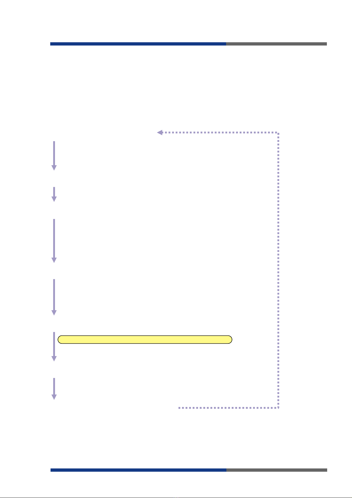
The technical measures for reducing the risk of dangerous states and damage to the
machine or material include the electrical equipment. The required level of risk
minimization and consequently the requirements of the safety-related parts on the
controller are determined for example according to EN ISO 13849-1 (here controller
category.
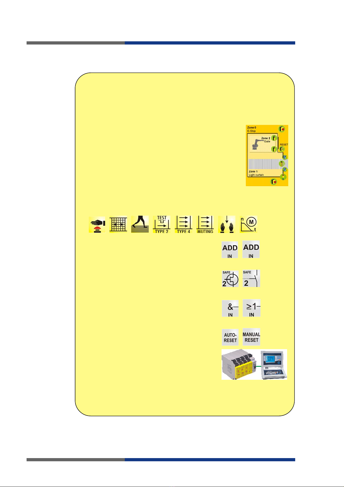
Creating safety zones
In risk analysis the machine is often divided into different safety
zones, which may have different risk potentials. The zones are
linked by safety logic functions so that only the necessary parts
of the machine are shut down when a safety event occurs.
Selecting safety devices and safety functions
for monitoring the safety equipment and safety zones. Selection
of stop category 0 and/or 1 (EN 60204-1).
Select function blocks and input circuit functions for the application on the samos
base module.
How many safety sensors and safety circuits
must also be monitored?
Select input expansions.
How many additional safety outputs are needed?
Select outputs on base module (semiconductor)
or output expansion (relay contacts)
Link safety zones
and function blocks in the samos system.
Select Reset behavior
for powering up and after safety event.
Select optional field bus function
as diagnosis function.
You can find examples
for logic functions on
page 53ff.
You can find an overview
of applications on page
19 and 36.
You can find descriptions
of input modules on page
32ff.
You can find descriptions
of base modules on page
13ff,
relay output modules on
page 42ff.
You can find examples
for logic functions on
page 53ff.
You can find the
descriptions of reset
behavior on page 24ff.
Bus coupler modules are
described in a separate
manual. You can find the
order numbers on page
70.
samos Safety System
© 2010 Wieland Electric GmbH | BA000256 | 12/2012 (Rev. I)
11
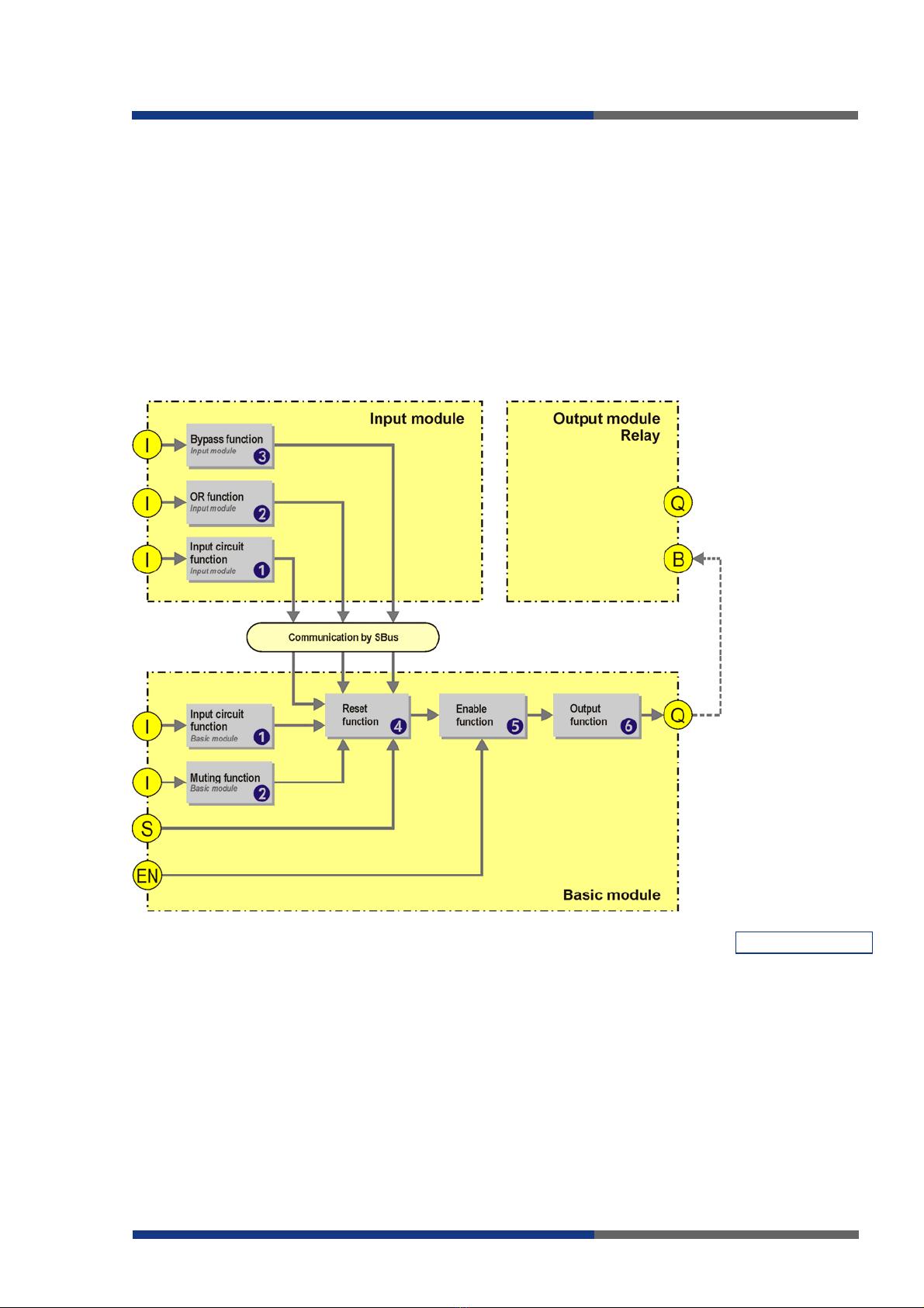
System Functions
The samos safety system is for monitoring sensors as part of the safety equipment of
machines. The safety function (e.g. an emergency stop function) is implemented by
switching outputs Qon or off safely in relation to the state of the sensors on inputs I, EN
(enable) and S(Reset condition). Switching these outputs on/off prevents dangerous states
occurring in the plant/ machine.
The safety function is made up of a chain of logically linked functions. The input
modules communicate with the associated base module (on the left) via the internal safety
bus (SBus). The relay output modules are not integrated directly via the SBus in the samos
safety communication system. However, indirect monitoring is possible via the feedback
circuits.
Input circuit function
The input circuit function logically links input signals for further processing. There are
different methods for activation:
Input circuit function single-channel via NC contact
Input circuit function with dual-channel equivalent activation,
with/without cross-circuit monitoring, with/without synchronous time monitoring
Input circuit function with dual-channel non-equivalent activation,
with/without cross-circuit monitoring, with/without synchronous time monitoring
Two-hand function with activation by one NO contact per hand (EN 574, IIIA)
Two-hand function with activation by NO/NC combination for each hand (EN 574, IIIC)
Dual-channel equivalent activation by semiconductor
Safety inputs

samos Safety System
12
© 2010 Wieland Electric GmbH | BA000256 | 12/2012 (Rev. I)
OR function and muting function
The off signal of an input function can be bridged with an OR signal. For example, in setup
mode a safety function can be bridged using an enabling button; an OR operation can also
link two safety functions.
The muting function is a special case of the OR function. For example, muting sensors
allow a conveyor belt to transport material through a light curtain by briefly bridging the
light curtain function.
___________________________________________________________________________
Bypass function
With a bypass signal the OFF signal of a Reset function (see page 47) can be changed into
an ON signal in the base module. Bypass is used when the system is to be switched on
after a power shutdown but a light barrier is obstructed by material. Bypass cancels the
safety function of the safety device, allowing the blockage to be cleared. In normal
operation the muting function bridges automatically (see above).
___________________________________________________________________________
Reset function
The Reset function defines which (Reset) conditions must be fulfilled if, for example, an
ON signal is to be passed on to the Reset function output. All input and muting signals
from the base module and the associated input modules, and the bypass/OR signals from
the input modules are logically linked (AND/OR). The terminal configuration with bridges
and feedback circuits is also evaluated.
___________________________________________________________________________
Enable function
The enable function enables the ON signal in the Reset function if there is H-level on the
EN input. The H-level for enabling can be generated, for example, by a semiconductor
output Q
n
on the base module for logic operations or a PLC output. For category 4
applications (EN ISO 13849-1) the module that generates the enabling signal must be in the
same enclosure. If the EN input is open or on L-level the following Q
n
semiconductor
outputs are locked.
___________________________________________________________________________
Output function
The time behavior of the safety ON/OFF signal is defined in the output function. Depending
on the function, you can set a off delay for outputs Q3 or Q3/Q4 between 0 and 5 minutes
(depending on module version).
___________________________________________________________________________
Communication
With the communication function system data is exchanged between the different
modules in a system via the internal safety bus (SBus).
___________________________________________________________________________
Diagnosis and display function
The diagnosis function allows internal system data to be provided to external systems via a
diagnosis module or bus coupler module.
For detailed explanations of system functions and other hints and examples please refer to
the glossary on page 45ff.
OR
Muting
Bypass
Reset
Enable
Safety outputs
Diagnosis
NOTE
© 2010 Wieland Electric GmbH | BA000256 | 12/2012 (Rev. I)
13
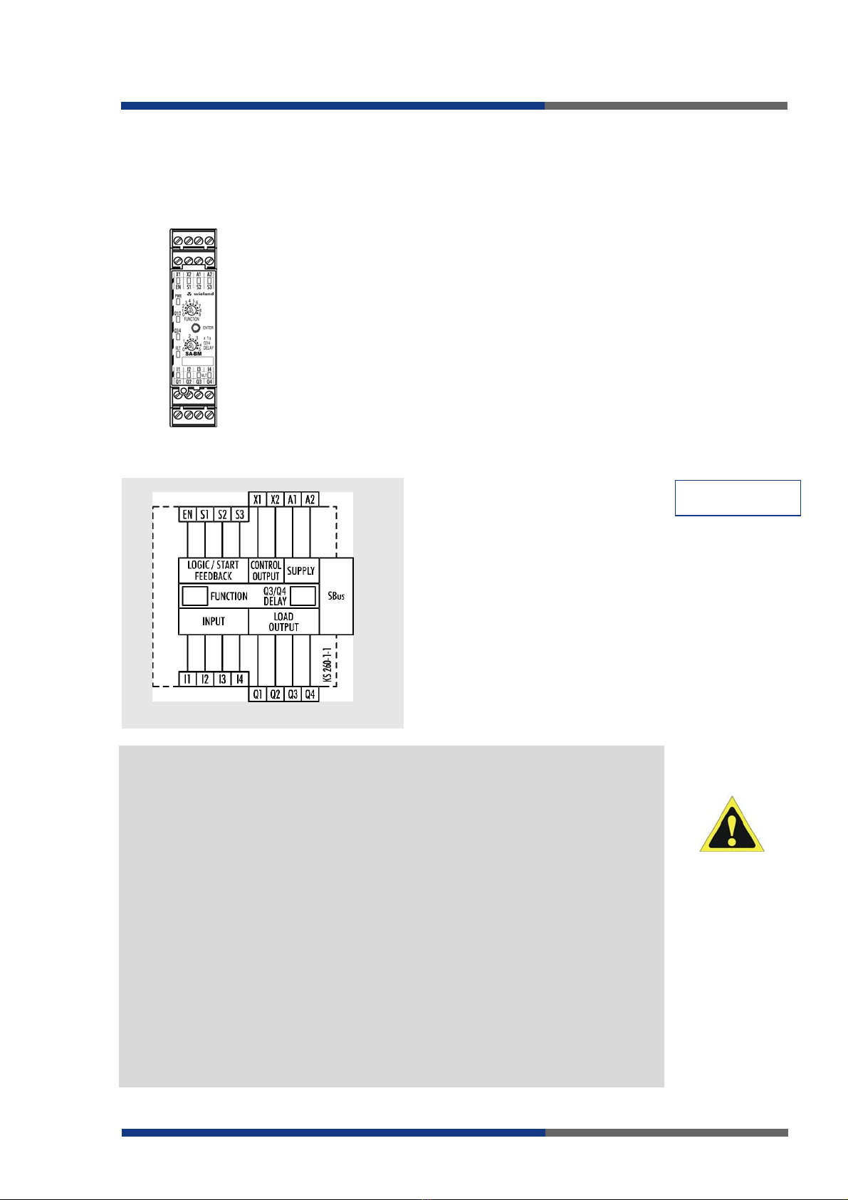
4SA-BM Base Module
Base Module Data
SA-BM-S1
Master base module
The SA-BM master base module is the obligatory
module of the samos system. On its own it functions
as a complete safety switching device for monitoring
up to 2 safety circuits.
SA-BM-S1
SA-BM-S1
The controller category (EN ISO 13849-1) or SIL (EN 61508/EN 62061) depends on the
external circuitry, the wiring, the choice of control devices and their location on the
machine.
In the event of single-channel control of a contact extension (e.g. SA-OR) through a base
module (SA-BM), category 4 according to EN ISO 13849-1 can be achieved if both
devices are installed in the same enclosure.
The SA-BM must be protected with a 6 A fuse of utilization category gG or a 6 A (4 A)
circuit-breaker (tripping characteristic B or C).
The rotary switches for selecting function and time must only be adjusted when power is
off.
Never connect or disconnect modules while the operating voltage is switched on.
If external contactors or relays are connected, the feedback circuits (NC contacts) must
be connected to the base module.
When inductive loads are connected (e.g. valves, contactors) a suppressor circuit must
be set up (e.g. RC combination).
Internal samos module addresses are assigned automatically when the system starts up.
Manual addressing is unnecessary (and not possible).
The safety system must be installed in an enclosure with at least IP 54 protection.
Each base module forms a system group within the overall system (sometimes together
with associated input expansion modules; see diagram on page 8).
Connection
diagram
Notes

SA-BM Base Module
14
© 2010 Wieland Electric GmbH | BA000256 | 12/2012 (Rev. I)
S
A
-BM-S1
Function Base module in the samos system
Function display 11 green LEDs, 1 red LED
Controls 2 10-position switches, 1 1-position button
Terminals Plug-in terminals with screws / spring force
Max. number of modules / status in system 1 / SBus master
Max. number of parallel-connected module inputs
In or S
n
that can be controlled from one module
output X
n
or Q
n
8
___________________________________________________________________________
Power circuitry (
A1, A2
) Min. Typical Max.
Operating voltage U
B
, DC 19.2 V 24 V 30.0 V
Residual ripple V
SS
3.0 V
Rated power, DC 1.8 W
Peak current I
P
25 A
Ready time t
ON
(after connecting U
B
) 10 s
Device fuse 6 A (gG)
___________________________________________________________________________
Input circuit (I1..I4, EN, S1..S3) Min. Typical Max.
Input voltage, U
E
(HIGH)
(LOW)
13.0 V
–0.5 V
30.0 V
5.0 V
Input current, I
E
(HIGH)
(LOW)
2.4 mA
–2.5 mA
3.0 mA
3.8 mA
2.1 mA
Cyclical peak input current, I
E,Peak
15 mA
Input capacitance, C
IN
200 nF
Input resistance, R
IN
8 k
ON period* t
E
70 ms
OFF period* t
A
> t
AN
Break time of U
E
(test pulses) 1.0 ms
Break time period 20 ms
Synchronous time t
S
(Function 2)
Synchronous time t
S
(Functions 4, 5.2)
1500 ms
500 ms
Duration of operation Reset inuts S1, S2 50 ms 5 s
___________________________________________________________________________
Output circuit (
X1, X2
) Min. Typical Max.
Output voltage 18.0 V 30.0 V
Output current 150 mA
Wire capacitance, C
L
500 nF
Wire resistance, R
L
100
Type of outputs / short-circuit behavior Semiconductor / absolutely short-circuit-proof
SA-BM
technical data
* For the times, see the
function diagram at the
end of the table
The sum of currents,
which are drained from
the outputs X1, X2 of all
Base modules to supply
external sensors, may not
exceed 600 mA!

SA-BM Base Module
© 2010 Wieland Electric GmbH | BA000256 | 12/2012 (Rev. I)
15
Output circuit (
Q1..Q4
) Min. Typical Max.
Output voltage 18.0 V 30.0 V
Output current (with U
N
= DC 24 V) res./ind. 2.0 A
Total current (see diagram) 4.0 A
Inductive switching off energy E (E=0,5*L*I²) 370 mJ
Settable off delay
Q3/Q4 or Q4, t
RV
(depending on device version)
0 / 0.5 / 1 /1.5 / 2 / 2.5 / 3 / 3.5 / 4 / 5 s
0 / 5 / 10 / 15 / 20 / 25 / 30 / 35 / 40 / 50 s
0 / 0.5 / 1 / 1.5 / 2 / 2.5 / 3 / 3.5 / 4 / 5 min
Test pulse width, t
TI,HL
500 μs
Test pulse period, t
TP,HL
32 ms 80 ms
Load capacitance, C
L
500 nF
Conductor length (single, 1.5 mm
2
) 100 m
Type of outputs / short-circuit behavior Semiconductor / absolutely short-circuit-proof
Parallel connection of outputs not allowed
___________________________________________________________________________
Input test t
TI
, typ. t
TD
, typ. t
TP
, typ.
Test pulse width* t
TI
;
Test duration** t
TD
;
Test pulse period t
TP
Function 3.1, 7, 8 no test pulses
Function 3.2 (BWStype 2)
Function 3.2 (PDF sensors)
Functions 1, 2, 4, 5, 6, 9
12 ms
52 ms
12 ms
20 ms
70 ms
20 ms
40 ms
384 ms
40 ms
___________________________________________________________________________
Response times Min. Typical Max.
Response time*** t
AN
(normal operation)
Functions 3.1, 7, 8
Function 3.2 (BWStype 2)
Function 3.2 (PDF sensors)
Functions 1 (except safety mat), 2, 4, 5.1, 6, 9
Function 1 (safety mat)
Function 5.2
13 ms
32 ms
79 ms
20 ms
38 ms
29 ms
DISABLE (via EN input) 13 ms
OR off to Qx off 9 ms
Function 3 (MUTING off to Qx off) 65 ms
EN off to Qx off 13 ms
___________________________________________________________________________
Safety parameters at ambient temperature T
B
+55 °C
PFD 1.7 x 10
-5
PFH 7.9 x 10
-9
h
-1
SFF 96 %
DC 93 %
MTTFd 158 years
___________________________________________________________________________
General data Min. Typical Max.
Enter button ON period 3 s
Isolation
Power circuitry – input circuit
Power circuitry – output circuit
Input circuit – output circuit
no
no
no
Weight 0.16 kg
General technical data See page 65.
Order numbers See page 69.
SA-BM
technical data
Diagram "Total current
vs. Temperature"
* Signal changes are not
detected during the test
pulse.
** Signal changes from
HIGH to LOW are not
detected during the test
pulse.
For the times see the
function diagrams at the
end of the table.
*** The response time tAN
is the time between the
OFF signal arriving at the
input terminals and the
outputs actually being shut
down (in normal
operation).
The response times of
any assigned input
modules must also be
taken into consideration.
See input module data,
page 33.
For information on
safety-related
parameters, see glossary
p. 49

SA-BM Base Module
16
© 2010 Wieland Electric GmbH | BA000256 | 12/2012 (Rev. I)
___________________________________________________________________________
Input test function diagram (with cross circuit monitoring)
Output X1
Output X2
Input I1/I3
Input I2/I4
tTI
tTI tTI
tTD
tTD
approx. 0.5
tTP approx. 0.5
tTP
___________________________________________________________________________
Input circuit function diagram (equivalent activation)
Input I1
Input I2
QIN (good state)
tE t
A
Function
diagrams
tTI : Test pulse width
tTD : Test duration
tTP : Test pulse period
tE: ON period
tA: OFF period
QIN: see page 47

SA-BM Base Module
© 2010 Wieland Electric GmbH | BA000256 | 12/2012 (Rev. I)
17
Interfaces and Operation
Clamps
A1, A2
X1, X2
EN
S1, S2, S3
I1, I2, I3
Q1, Q2, Q3
SBus
Voltage supply of the basic module and the
corresponding extension module (Plus
voltage at A1)
Outputs only for voltage supply of inputs of
the module or rather the control of the
sensors
Input for enabling the outputs
Control inputs for the configuration of mode
of operation and the connection of reset
buttons / feedback circuits
Inputs for the connection of signal
transmitters / sensors
Outputs for the controlling of actuators
10-pin connector for safety bus
- SA-BM: just nut (coded)
Push-buttons
FUNCTION
Q3/4 DELAY
ENTER
S1, S2, S3
8-staged torque switch for adjustment of an
input circuit function
10-staged torque switch for adjustment of
the fall-back delay time
Button for the assumption of system
configuration (just SA-BM)
LEDs
EN, S1 .. S3, I1.. I4
(green)
PWR (green)
Q1/2, Q3/4 (green)
FLT (red)
Indicators of according inputs
Voltage supply
Switching status of the semiconductor
outputs
Indicator of flawed operating modes
(see FLT error codes page 63)
___________________________________________________________________________
PWR on
I1-I4 on
I1, I2 flash simultaneously
I3, I4 flash simultaneously
I1, I2 flash alternately
I3, I4 flash alternately
I1 oder I2 flashes
I3 oder I4 flashes
EN, S1..S3 on
S1..S3 flashes
Q1/2, Q3/4 on
FLT off
Power supply to module electronics is on
H-level on corresponding input
Cross-circuit between I1 and I2
Cross-circuit between I3 and I4
Sequence error on I1, I2
Sequence error on I3, I4
Synchronous time error. The input that flashes is the one
that achieves good state too late.
Synchronous time error. The input that flashes is the one
that achieves good state too late.
H-level on corresponding input
Feedback circuit open
H-level on corresponding outputs, Q3/4 flashes during off
delay time
No fault states
Interfaces
Meaning of LEDs

SA-BM Base Module
18
© 2010 Wieland Electric GmbH | BA000256 | 12/2012 (Rev. I)
Interfaces and Operation
First installation and Accepting the system configuration
Configurations can only be set or altered using the switches
and terminals when the whole system is switched off, i.e.
when there is no operating voltage on terminals A1/A2 on
any base module. After the required functions and control
circuit functions have been set on all the modules in the
system (using the rotary switches and external circuitry on
terminals S1, S2, S3 respectively), operating voltage must
be connected while the ENTER button on the SA-BM base
module is pressed and held. As soon as the FLT indicator
starts blinking the ENTER button must be released within 3
seconds. Then the selected mode is saved in non-volatile
form and active. If the ENTER button is pressed for longer
than 5 seconds after the LED has started blinking, the FLT
display will indicate a fault (blinking light).
Terminals S1, S2, S3 serve not only to set the mode; they
can also be used for feedback-circuit monitoring of
connected relays and contactors. This means that the
terminal signals change during operation (opened
contact). The set mode remains unaffected because it is
only detected, checked and saved when the system is
switched on or restarted.
Because the relay expansion modules are not directly inte-
grated in the communication or diagnosis of the samos
system via the internal safety bus, changes in their
input/output circuitry are registered only indirectly via the
feedback circuits.
___________________________________________________________________________
Manipulation, handling errors and operating errors during operation
Manipulating the system configuration (e.g. operating a
rotary switch or adding or removing modules causes
immediate canceling of enabling. To assist in setting the
valid configuration the green PWR LED on the module
changes from blinking to continuous when the respective
switch position has been restored. A restart (switch off
and on again) under the set Reset condition is possible
when the former configuration has been restored. The
ENTER key has no effect during operation.
If the new configuration is to be adopted you have to go
through the “accept configuration” procedure described
above.
We recommend keeping a record of the configuration
with the documentation or in a clearly visible place in the
enclosure. One way to check the system configuration is to
output a checksum of the configuration data via a connected
bus coupler module.
There is a separate manual for the bus coupler modules
(see page 70).
Accepting
configuration
NOTES
Handling errors
NOTES
There is a blank confi-
guration list for copying
inside the back cover.
Notes on downloading an
online version on page 74.
SA-BM Base Module
© 2010 Wieland Electric GmbH | BA000256 | 12/2012 (Rev. I)
19
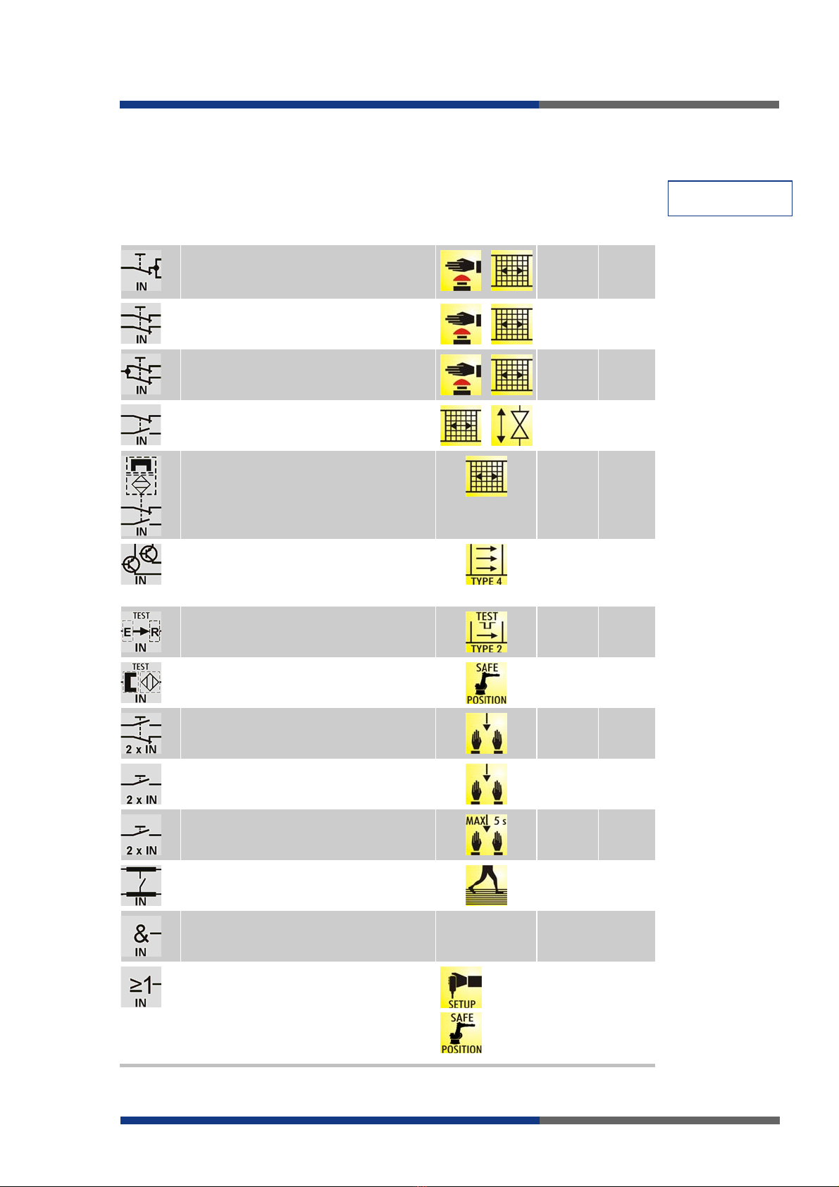
Input Circuit Functions
Overview of possible applications and corresponding sensor connections
Sensor
connection
Application e.g. Module/
group *
Category
up to **
Emergency stop / safety door
Single-channel NC
3AB
7A/7B
8A/8B
2
Emergency stop / safety door
Dual-channel equivalent NC
Cross-circuit monitoring
1AB
5A
6A/6B
4
Emergency stop / safety door
Dual-channel three-wire equivalent NC
3AB
7A/7B
8A/8B
3
Safety door or valve
Dual-channel equivalent NC/NO
2AB 4
Coded electromagnetic switch
on safety door
Dual-channel non-equivalent NC/NO
2AB 4
Access monitoring with self-testing sensors
(e.g. outputs from light curtain type 4)
dual-channel single-ended positive switching
semiconductor
3AB
7A/7B
8A/8B
4
Access monitoring with testable sensors (e.g.
type 2 light barriers) or potential-free contacts
Single-channel NC/semiconductor outputs
3AB 2
Position monitoring with testable inductive
sensors (PDF)
Single-channel NC/semiconductor outputs
3AB 4
Two-hand control
acc. to EN 574 IIIC or safety door
2x dual-channel non-equivalent NO/NC
4AB 4
Two-hand control acc. to
EN 574 IIIA (not for press control)
2x single-channel NO
5B 2
Jog mode max. 5 s (e.g. setup mode)
2x single-channel NO
5B 2
Access monitoring with short-circuiting
switching mats
Four-wire
1AB 3
AND operation
Enabling input for cascading and grouping
In base module:
Sensor inputs:
all function blocks
input module
OR operation
Muting, OR, bypass
for bridging safety functions for setup mode,
clearing, alternative safety function
Muting:
OR:
Bypass:
3AB
1AB, 2AB,
input module
input module
Overview of
applications
* Availability of
applications/sensor
connections in function
blocks (1 to 8) and
function groups (A, B).
See page 20.
** Maximum control
category (depends on
sensor, wiring and
installation
Please also note the
information on page 13.

SA-BM Base Module
20
© 2010 Wieland Electric GmbH | BA000256 | 12/2012 (Rev. I)
Input Circuit Functions
Using the rotary FUNCTION switch on the front you can set 8 function blocks as single,
combination or dual functions. On their own or in appropriate combinations these function
blocks cover the main fields of safety application. Using terminal combinations you can set
Reset behavior for manual/automatic Reset (page 24), off delay retriggering (page 25) and
special functions (page 23). Switch positions 0 and 9 are without function and must not be
used.
Single functions 1 to 4
The input circuits of function groups Aand Bact jointly on output circuits Q1 to Q4
(exception: function 3 with Q3 as muting lamp / Reset required output). In functions 1
and 2 settable off delay and retriggering act jointly on outputs Q3 and Q4; in function 3
only on Q4; in function 4 no off delay can be set.
Combination functions 5 to 7
The input circuits of function group Aact directly on all output circuits Q1 to Q4; the input
circuits of function group Bact on output circuits Q3 and Q4.
They are AND-linked via the internal logic with input circuits A. This allows the safety
concept found on many machines (two safety zones, one group subordinate) to be
reproduced within the device. With the exception of function 5 (for which no off delay is
settable) the settable off delay and retriggering act only on output Q4.
Dual function
The input circuits of function groups Aand Bact separately on output circuits Q1, Q2 or
Q3, Q4. This means that with one base module you can monitor two independent safety
groups on a machine or system. Settable off delay and retriggering act only on output
Q4.
Evaluating input circuits / function blocks
The diagram shows three different types of evaluation and the signal flows between inputs
and outputs for single function 1, combination function 6 and dual function 8. The diagram
is an excerpt from the function overview (see page 30).
together linked separate
Table of contents
Other Wieland Switch manuals

Wieland
Wieland SIN 1 Series User manual

Wieland
Wieland wienet UMS 8-C User manual

Wieland
Wieland wienet FS8 Series User manual

Wieland
Wieland SIN 1 Series User manual

Wieland
Wieland SNO 4003K User manual

Wieland
Wieland wienet IP SWITCH UMS 8-W-M12 User manual

Wieland
Wieland UMS 6-C-1G-4PoE-1SFP-W User manual

Wieland
Wieland SNA 4043KE User manual

Wieland
Wieland wienet UMS 5-C-4G-1SFP-W User manual

Wieland
Wieland SNO 4063K-A User manual


