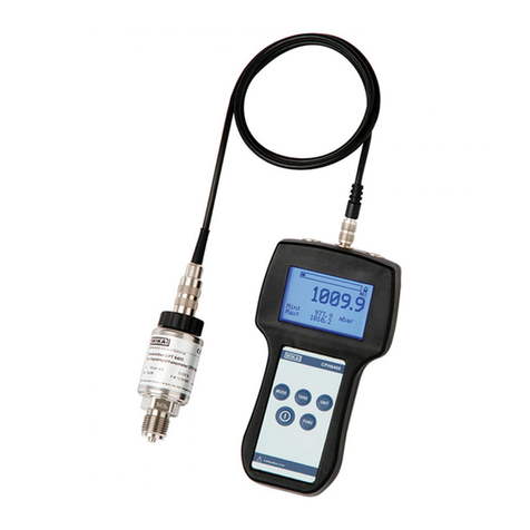
WIKA CPH62I0-S1 User manual

Operating instructions
Betriebsanleitung
Mode d'emploi
Manual de instrucciones
GB
D
F
E
Intrinsically safe hand-held pressure indicator,
model CPH62I0-S1/CPH62I0-S2
Eigensicheres Hand-Held Druckmessgerät,
Typ CPH62I0-S1/CPH62I0-S2
Indicateur de pression portable à sécurité intrinsèque,
type CPH62I0-S1/CPH62I0-S2
Manómetro portátil de seguridad intrínseca,
modelo CPH62I0-S1/CPH62I0-S2
Intrinsically safe hand-held pressure indicator,
model CPH62I0-S1/CPH62I0-S2

2
11221801.02 02/2011 GB/D/F/E
WIKA operating instructions, model CPH62I0
GB
D
F
E
Operating instructions
model CPH62I0-S1/CPH62I0-S2 Page 3 - 44
Betriebsanleitung
Typ CPH62I0-S1/CPH62I0-S2 Seite 45 - 86
Mode d'emploi
type CPH62I0-S1/CPH62I0-S2 Page 87 - 122
Manual de instrucciones
modelos CPH62I0-S1/CPH62I0-S2 Página 123 - 158
© 2005 WIKA Alexander Wiegand SE & Co. KG
All rights reserved. / Alle Rechte vorbehalten.
WIKA®is a registered trademark in various countries.
WIKA®ist eine geschützte Marke in verschiedenen Ländern.
Prior to starting any work, read the operating instructions!
Keep for later use!
Vor Beginn aller Arbeiten Betriebsanleitung lesen!
Zum späteren Gebrauch aufbewahren!
Lire le mode d'emploi avant de commencer toute opération !
A conserver pour une utilisation ultérieure !
¡Leer el manual de instrucciones antes de comenzar cualquier trabajo!
¡Guardar el manual para una eventual consulta!

3WIKA operating instructions, model CPH62I0
11221801.02 02/2011 GB/D/F/E
GB
Contents
1. General information 4
2. Safety 5
3. Specications 11
4. Design and function 14
5. Transport, packaging and storage 17
6. Commissioning, operation 18
7. Maintenance, cleaning and servicing (recalibration) 31
8. Faults 32
9. Dismounting, return and disposal 34
10. Accessories 35
Appendix 1: EC Declaration of Conformity for model
CPH62I0 36
Appendix 2: EC Declaration of Conformity for model
CPT62I0 37
Appendix 3: EC-type examination certicate for model
CPH62I0 (only in German) 38
Appendix 4: EC-type examination certicate for model
CPT62I0 41
Declarations of conformity can be found online at www.wika.com.
Contents

4 WIKA operating instructions, model CPH62I0
11221801.02 02/2011 GB/D/F/E
GB
1. General information
■
The hand-held pressure indicator described in the operating instructions has been
designed and manufactured using state-of-the-art technology.
All components are subject to stringent quality and environmental criteria during
production. Our management systems are certied to ISO 9001 and ISO 14001.
■
These operating instructions contain important information on handling the hand-
held pressure indicator. Working safely requires that all safety instructions and work
instructions are observed.
■
Observe the relevant local accident prevention regulations and general safety regula-
tions for the hand-held pressure indicator’s range of use.
■
The operating instructions are part of the instrument and must be kept in the immedi-
ate vicinity of the hand-held pressure indicator and readily accessible to skilled
personnel at any time.
■
Skilled personnel must have carefully read and understood the operating instruc-
tions, prior to beginning any work.
■
The manufacturer’s liability is void in the case of any damage caused by using the
product contrary to its intended use, non-compliance with these operating instruc-
tions, assignment of insuciently qualied skilled personnel or unauthorised modi-
cations to the hand-held pressure indicator.
■
The general terms and conditions, contained in the sales documentation, shall apply.
■
Subject to technical modications.
■
Factory calibrations / DKD/DAkkS calibrations are carried out in accordance with
international standards.
■
Further information:
- Internet address: www.wika.de / www.wika.com
- Relevant data sheet: CT 11.02
- Application consultant: Tel.: (+49) 9372/132-9986
Fax: (+49) 9372/132-8767
E-Mail: [email protected]

5WIKA operating instructions, model CPH62I0
11221801.02 02/2011 GB/D/F/E
GB
1. General information / 2. Safety
Explanation of symbols
WARNING!
... indicates a potentially dangerous situation that can result in serious
injury or death, if not avoided.
CAUTION!
... indicates a potentially dangerous situation that can result in light
injuries or damage to equipment or the environment, if not avoided.
Information
... points out useful tips, recommendations and information for ecient
and trouble-free operation.
DANGER!
...identies hazards caused by electric power. Should the safety instruc-
tions not be observed, there is a risk of serious or fatal injury.
WARNING!
... indicates a potentially dangerous situation in the hazardous area,
which can result in serious injury or death, if not avoided.
2. Safety
WARNING!
Before installation, commissioning and operation, ensure that the
appropriate hand-held pressure indicator and the appropriate pressure
sensor has been selected in terms of measuring range, design and
specic measuring conditions.
Non-observance can result in serious injury and/or damage to equip-
ment.
Further important safety instructions can be found in the individual
chapters of these operating instructions.

6 WIKA operating instructions, model CPH62I0
11221801.02 02/2011 GB/D/F/E
GB
2. Safety
2.1 Intended use
The CPH62I0 hand-held pressure indicator can be used as a calibrator, and for any
application where an accurate pressure measurement is required, within hazardous
areas.
The hand-held pressure indicator has been designed and built solely for the intended
use described here, and may only be used accordingly.
The technical specications contained in these operating instructions must be
observed. Should the hand-held pressure indicator be improperly handled or operated
outside of its technical specications, it has to be taken out of service immediately and
inspected by an authorised WIKA service engineer.
Handle electronic precision measuring instruments with the required care (protect from
humidity, impacts, strong magnetic elds, static electricity and extreme temperatures,
do not insert any objects into the instrument or its openings). Plugs and sockets must be
protected from contamination.
If the hand-held pressure indicator is transported from a cold into a warm environment,
the formation of condensation may result in the instrument malfunctioning. Before
putting it back into operation, wait for the instrument temperature and the room tempera-
ture to equalise.
The manufacturer shall not be liable for claims of any type based on operation contrary
to the intended use.
2.2 Personnel qualication
WARNING!
Risk of injury should qualication be insucient!
Improper handling can result in considerable injury and damage to
equipment.
The activities described in these operating instructions may only be
carried out by skilled personnel who have the qualications described
below.
Skilled personnel
Skilled personnel are understood to be personnel who, based on their technical training,
knowledge of measurement and control technology and on their experience and knowl-
edge of country-specic regulations, current standards and directives, are capable of
carrying out the work described and independently recognising potential hazards.

7WIKA operating instructions, model CPH62I0
11221801.02 02/2011 GB/D/F/E
GB
2. Safety
Special operating conditions require further appropriate knowledge, e.g. of aggressive
media.
2.3 Additional safety instructions for instruments with ATEX approval
WARNING!
Non-observance of these instructions and their contents may result in
the loss of explosion protection.
The CPH62I0 hand-held pressure indicator is used for measuring
absolute and/or gauge pressures. In addition, the 2-channel version
can be used to measure dierential pressure. The measurement is
carried out by an external pressure sensor.
■
Battery operation:
Only the usage of approved 9 V batteries allowed!
Batteries may only be changed outside of the hazardous area!
Approved batteries are:
Battery type Manufacturer Battery name
6F22 GB GREENCELL, 9 V (1604G)
6LF22
or
6LR61
GP SUPER Alkaline, 9 V (1604A)
Duracell DURACELL PLUS, Alkaline, 9 V
Varta powerone alkaline, 9 V (No. 4122)
Varta INDUSTRIAL, Alkaline, 9V (No. 4022)
■
Ex-Zone operation:
Within Ex-Zones the accompanying leather case must be used!
■
Serial interface:
The serial interface may not be used within hazardous areas.
Connection and operation are only permitted to be used outside of
hazardous areas!
Only the WIKA interface converter may be used!
■
Pressure sensor:
You must only use model CPT62I0 pressure sensors! Usage of
other sensors may result in damage to the sensor and instrument.
When operating with two model CPT62I0 pressure sensors, be
careful that the sensors are not screwed into, nor are in contact
with, surfaces with diering electrical potentials.

8 WIKA operating instructions, model CPH62I0
11221801.02 02/2011 GB/D/F/E
GB
2. Safety
Only use the original WIKA connecting cable, which is provided
specically for connecting the CPT62I0 pressure sensor to the
CPH62I0 hand-held pressure indicator. The same applies to the
extension cable, which may be used to a maximum permissible
length of 5 m.
■
Temperature range:
Do not operate below -10 °C. Permissible ambient temperature
range: -10 ... +50 °C
■
Mains operation:
Only use WIKA power supplies! Operation with the external power
supply is not permitted in hazardous areas!
■
Analogue output:
The analogue output must not be used in hazardous areas!
Only use the analogue output with a passive voltmeter.
■
Equipotential bonding:
Do not apply dierent potentials to the components connected to
the instrument (pressure sensor, power supply, interface) and do
not connect them by means of an equipotential bonding.
Only connect pressure sensors for operation in hazardous areas!
If two pressure sensors are connected, make sure that they are
connected to the same electrical potential or have an equipotential
bonding.
■
Ambient conditions:
Take care that the device is not exposed to environments that
enable the ingress of humidity, water, conducting liquids or dust.
■
Non intrinsically-safe use:
The hand-held pressure indicator can also be used as non intrinsi-
cally-safe device for connection to non intrinsically-safe devices (i.e.
power supply unit, interface converter, etc.).
Likewise, only approved accessories may be used in this operating
mode!
Before the hand-held pressure indicator is once again used as an
intrinsically-safe device, it must be checked for visible damage and
correct functioning before it is returned to its leather case!

9WIKA operating instructions, model CPH62I0
11221801.02 02/2011 GB/D/F/E
GB
2. Safety
2.4 Special hazards
WARNING!
Observe the information given in the applicable type examination
certicate and the relevant country-specic regulations for installation
and use in hazardous areas (e.g.
VDE 0165,
IEC 60079-14, NEC, CEC).
Non-observance can result in serious injury and/or damage to equip-
ment.
For additional important safety instructions for insturments with ATEX
approval see chapter “2.3 Additional safety instructions for instruments
with ATEX approval”.
WARNING!
For hazardous media such as oxygen, acetylene, ammable or toxic
gases or liquids, and refrigeration plants, compressors, etc., in addition
to all standard regulations, the appropriate existing codes or regula-
tions must also be followed.
DANGER!
Danger of death caused by electric current
Upon contact with live parts, there is a direct danger of death.
Operation using a defective power supply unit (e.g. short circuit from
the mains voltage to the output voltage) can result in life-threatening
voltages on the hand-held pressure indicator!
WARNING!
Residual media in dismounted hand-held pressure indicator or
pressure sensor can result in a risk to persons, the environment and
the equipment.
Take sucient precautionary measures.
Should a failure occur, aggressive media with extremely high tempera-
ture and under high pressure or vacuum may be present at the
handheld pressure indicator’s sensors.
If there is a possibility that the instrument can no longer be used safely, the instrument
must be switched o immediately and marked accordingly to prevent re-use.
The safety of the operator may be endangered if, for example:
■
there is visible damage to the instrument.
■
the instrument is not working as specied.
■
the instrument has been stored under unsuitable conditions for an extended period of
time.
If there is any doubt, please return the instrument to the manufacturer for repair or
maintenance.
10 WIKA operating instructions, model CPH62I0
11221801.02 02/2011 GB/D/F/E
GB
2. Safety
Code of the notied body monitoring
the quality assurance system for the
production
2.5 Labelling / Safety marks
5.2.1 Product label for hand-held pressure indicator
Explanation of symbols
Before mounting and commissioning the hand-held pressure indicator,
ensure you read the operating instructions!
CE, Communauté Européenne
Hand-held pressure indicators bearing this mark comply with the
relevant European directives.
ATEX European Explosion Protection Directive
(Atmosphère = AT, explosible = Ex)
Hand-held pressure indicators bearing this mark comply with the
requirements of the European Directive 94/9/EC (ATEX) on explosion
protection.
This marking on the instruments indicates that they must not be
disposed of in domestic waste.The disposal is carried out by return to
the manufacturer or by the corresponding municipal authorities. See EU
Directive 2002/96/EC.
2.5.2 Product label for pressure sensor
For an explanation of symbols, see below
Date of manufacture (year/month)
Approval number
Approval number
Model:
1-channel version: CPH62I0-S1
2-channel version: CPH62I0-S2
Model

11WIKA operating instructions, model CPH62I0
11221801.02 02/2011 GB/D/F/E
GB
3. Specications
3. Specications
Specications
CPH62I0 hand-held indicator (complete measuring chain)
Input 1 input for CPH62I0-S1 2 inputs for CPH62I0-S2
Pressure range 1) bar 0.1 0.16 0.25 0.4 0.6 1.0 1.6 2.5 4.0 6.0 10
Over pressure safety bar 1 1.5 2 2 4 5 10 10 17 35 35
Burst pressure bar 2 2 2.4 2.4 4.8 6 12 12 20.5 42 42
Resolution (max.) depending on pressure range
Pressure range 1) bar 16 25 40 60 100 160 250 400 600 1000
Over pressure safety bar 80 50 80 120 200 320 500 800 1200 1500
Burst pressure bar 96 250 400 550 800 1000 1200 1700 2400 3000
Resolution (max.) depending on pressure range
Type of pressure gauge {absolute 0.25 up to 16 bar & vacuum on request}
Accuracy (measurement chain)
0.2 % FS ± 1 digit at reference temperature of 20 °C; optional: 0.1 %
Display Large LCD display for display of 2 values and additional information
Range of display max. -19999 up to 19999, depending on sensors used
Units can be selected: bar, mbar, psi, Pa, kPa, MPa, mmHg and inHg (dependent on
range)
Specications CPH62I0 digital instrument
Functions via key press Min-, Max-memory, Hold, Tare, Oset-correction, Logger (Start/Stop)
Functions via Menu
Min-, Max-alarm (visual), Sealevel (barom. air pressure), Power-O-Function,
measurement rate: 4/sec (“slow“); > 1000/sec (“fast“); > 1000/sec unltered (“peak-
detect“) [via “peak-detect“ and min-/max-memory: pressure peaks of 1.5 msec can
be detected]
Data logger - discrete value logger: up to 99 recordings incl. time via key press
- cyclic logger: automatic recording up to 10,000 values incl. time
- cycle time: selectable from 1 ... 3600 seconds
Interface (serial) 2) USB or RS-232 interface via special interface cable
Analogue output 2) 0 ... 1 V; congurable (alternative instead of serial interface, selectable via menu)
Power supply 9 V-zinc-carbon battery, alternative: 9 V rechargeable battery or mains supply
Power consumption cycle time slow: < 1.6 mA, fast: < 7.0 mA, Low-Power-Logger-Fct.: < 0.3 mA
Permissible
■
Working temperature °C -10 ... +50
■
Air humidity % r. H. 0 ... 95 relative humidity without moisture condensation
■
Storage temperature °C -20 ... +70
Housing
Impact-resistant ABS, membrane keyboard, transparent panels with protective leather
case
Weight g approx. 160
Connection values
■
Max. voltage DC V Uo= 10,38
■
Max. strength of current mA Io = 93
■
Max. power mW Po= 240
■
Max. eective internal capacitance nF Co= 1240
■
Max. eective internal inductance Lonegligible
CE conformity
■
EMC directive
2004/108/EC, EN 61326 Emission (Group 1, Class B) and Immunity (portable
equipment)
■
ATEX directive 94/9/EC, Category 2G, Ignition protection type Ex ib IIC T4
1) In an oxygen version, a ush diaphragm model is not available. In an oxygen version model CPT62I0 is only available in gauge pressure ranges ≥ 0.25
bar with media temperatures between -10 … +50 °C and using stainless steel or Elgiloy®wetted parts.
2) For the intrinsically safe version, the use of the interface and analogue output is not permitted within an explosive atmosphere.
3) O-ring made of FKM/FPM or EPDM for ush diaphragm with integrated cooling element.
{} Items in curved brackets are optional extras for additional price.

12 WIKA operating instructions, model CPH62I0
11221801.02 02/2011 GB/D/F/E
GB
3. Specications
Specications CPT62I0 reference pressure sensor
Pressure connection 1) G½ B; {ush diaphragm (G1 for 0.1 up to 1.6 bar) or various connection adapters
on request}
Material
■
Wetted parts Stainless steel or Elgiloy®, (> 25 bar with NBR seal)
ush diaphragm version: stainless steel {Hastelloy C4}; O-Ring: NBR 3) {FKM/FPM
or EPDM}
■
Internal transmission uid Synthetic oil, (only for pressure ranges up to 16 bar or ush diaphragm)
{Halocarbon oil for oxygen applications}; {Listed by FDA for food industry}
One year stability 0.2 % of span at reference conditions
Permissible
■
Medium temperature 1) °C -20 ... +50 (T4)
■
Ambient temperature °C -20 ... +50 (T4)
■
Storage temperature °C -40 ... +80
Protection class IP 67 (Sensor) / IP 54 (Plug)
Compensated range °C 0 ... 70
Temperature coecients
■
Mean TC of zero signal 0.2 % / 10 K (< 0.4 for pressure ranges < 250 mbar)
■
Mean TC of span 0.2 % / 10 K
Supply circiut
■
Max. voltage DC V Ui= 10,4
■
Max. strength of current mA Ii = 93
■
Max. power mW Pi= 500
■
Max. eective internal capacitance nF Ci= 600
■
Max. eective internal inductance Linegligible
CE conformity
■
Pressure equipment directive 97/23/EC
■
EMC directive 2004/108/EC, EN 61326 Emission (Group 1, Class B) and Immunity (portable
equipment)
■
ATEX directive 94/9/EC, Category 2G, Ignition protection type Ex ib IIC T4
Connection to CPH62I0 via 1 m cable (plug & play); on request: up to 5 m
Weight g approx. 220
1) In an oxygen version, a ush diaphragm model is not available. In an oxygen version model CPT62I0 is only available in gauge pressure ranges ≥ 0.25
bar with media temperatures between -10 … +50 °C and using stainless steel or Elgiloy®wetted parts.
2) For the intrinsically safe version, the use of the interface and analogue output is not permitted within an explosive atmosphere.
3) O-ring made of FKM/FPM or EPDM for ush diaphragm with integrated cooling element.
{} Items in curved brackets are optional extras for additional price.
For further specications see WIKA data sheet
CT 11.02
and the order documentation.
WARNING!
For further important safety instructions for the operation in hazardous
areas see chapter “2.3 Additional safety instructions for instruments
with ATEX approval”.

13WIKA operating instructions, model CPH62I0
11221801.02 02/2011 GB/D/F/E
GB
3. Specications
Dimensions in mm
Connection for interface adapter 1)
(under the Ex-protective leather
case)
Option: 2-channel versions
Pressure sensor CPT62I0Digital instrument CPH62I0
Top view Side view (left)
Note: The intrinsically safe version CPH62I0 in a protective leather case has no rubber base on the back.
Electrical connections to the digital instrument
1) For the intrinsically safe version CPH62I0 the use of the interface and power supply unit is not permitted within an explosive
atmosphere.

14 WIKA operating instructions, model CPH62I0
11221801.02 02/2011 GB/D/F/E
GB
4. Design and function
6
1
2
3
4
5
4. Design and function
4.1 Short description / Description
The CPH62I0 hand-held pressure indicator can be used as a calibrator and for any
application where an accurate pressure measurement is required, within hazardous
areas.
Pressure sensors with ranges up to 1,000 bar are available for the CPH62I0 hand-
held pressure indicator. This hand-held pressure indicator recognises the range of the
connected pressure sensor automatically and guarantees high precision.
Both gauge and absolute pressure ranges can be measured, and by using the
CPH62I0-S2 with two connected pressure sensors, it is also possible to measure dier-
ential pressure.Via menu selection, pressures can be displayed in bar, mbar, psi, Pa,
kPa, MPa, mmHg or inHg.
An integrated data logger and various other functions (such as Min, Max, Hold, Tare,
Oset correction, Alarm, Power-o, 3 Sample rates, Sealevel etc.) ensure that the
instrument can be used for many dierent applications.
4.2 Scope of delivery
■
CPH62I0-S1 or CPH62I0-S2: Intrinsically safe version EX ib IIC T4 or ATEX directive
94/9/EC incl. 9 V battery
■
One sensor connection cable per channel
■
Calibration certicate 3.1 per DIN EN 10204
■
Choice of sensors
Cross-check scope of delivery with delivery note.
4.3 Display
1. Main display: shows the current measured value of CH1.
2.
Lower display: For the 2-channel version, shows the measured value of CH2 or DIF
(CH1-CH2). For the 1 channel version, it displays the min, max or hold function values.
3. Logg: shown if logger function is selected, ashes if cyclic logger is running.

15WIKA operating instructions, model CPH62I0
11221801.02 02/2011 GB/D/F/E
GB
4. Design and function
4. Tare: indicates that the tare function is activated.
5. SL: indicates, that the sea level function is activated.
6. Measuring unit: an arrow points to the chosen measuring unit.
4.4 Electrical connections
On the upper edge of the device are located the connector sockets for attaching the
CPH series pressure sensors, CH1 and CH2 (CH2 only with the 2-channel version),
(see chapter “6.6 Available pressure sensors”), as is the socket for the WIKA interface
cable (see chapter “6.5 The serial interface”).
WARNING!
Operation as analogue output:
Connection via suitable cable.
Attention: The output mode must be congured via menu and inu-
ences battery life!
On the left side of the device the mains adapter socket for connecting the power
supply unit is located (see current CPH62I0 price list).
4.5 Power supply
Battery operation status
If ´bAt´ are shown in the lower display the battery is low and needs to be replaced.The
device will, however, work normally for a limited period. If ´bAt´ is shown in the upper
display the voltage is too low to operate the device; the battery will be completely at.
Connection for WIKA interface
cable (RS-232/USB) or optional
analogue output
CH1 CH2 (only for 2-channel version:
CPH62I0-S2)

16 WIKA operating instructions, model CPH62I0
11221801.02 02/2011 GB/D/F/E
GB
4. Design and function
If the device will not be used for some time, we advise that the battery
is removed.The real time clock has to be set again once the battery
has been reconnected.
Only the usage of approved batteries is allowed!
Approved batteries are:
Battery type Manufacturer Battery name
6F22 GB GREENCELL, 9 V (1604G)
6LF22
or
6LR61
GP SUPER Alkaline, 9 V (1604A)
Duracell DURACELL PLUS, Alkaline, 9 V
Varta powerone alkaline, 9 V (No. 4122)
Varta INDUSTRIAL, Alkaline, 9V (No. 4022)
4.6 Pressure sensors
Connecting/Changing pressure sensors
Only use model CPT62I0 pressure sensors. Using other pressure sensors can damage
the instrument! Switch o the device before changing the pressure sensor, and connect
the pressure sensor before turning the device back on, otherwise the pressure sensor
might not be identied correctly.
The hand-held pressure indicator and the pressure sensor are connected using a
discrete connecting cable.When changing the pressure sensor, always connect and
disconnect at the pressure sensor end of the cable.
To connect the pressure sensor, rotate the plug till it locates in the guide slot, allowing it
to plug in. Then tighten the safety collar (by screwing it lightly in a clockwise direction).
When connecting the cable to the pressure indicator, the connector might not locate
properly in the socket. In this event you should try holding the plug by the cable strain
relief, rather than by the connector housing. If the plug is correctly located, it will slide in
smoothly. To disconnect the pressure sensor hold it by the plug to release the connector
lock. Do not pull the cable to release it.
WARNING!
For gauge sensors, the pressure compensation vent hole is found at
the top of the sensor housing. This vent (with integral membrane seal)
must be kept clear without fail!

17WIKA operating instructions, model CPH62I0
11221801.02 02/2011 GB/D/F/E
GB
5. Transport, packaging and storage
5.1 Transport
Check hand-held pressure indicator for any damage that may have been caused by
transport. Obvious damage must be reported immediately.
5.2 Packaging
Do not remove packaging until just before mounting.
Keep the packaging as it will provide optimum protection during transport (e.g. change
in installation site, sending for repair).
5.3 Storage
Permissible conditions at the place of storage:
■
Storage temperature: -20 ... +70 °C
■
Humidity: 0 ... 95 % relative humidity (no condensation)
Avoid exposure to the following factors:
■
Direct sunlight or proximity to hot objects
■
Mechanical vibration, mechanical shock (putting it down hard)
■
Soot, vapour, dust and corrosive gases
Store the hand-held pressure indicator in its original packaging in a location that fulls
the conditions listed above. If the original packaging is not available, pack and store the
hand-held pressure indicator as described below:
1. Wrap the hand-held pressure indicator in an antistatic plastic lm.
2. Place the hand-held pressure indicator, along with shock-absorbent material, in the
packaging.
3. If stored for a prolonged period of time (more than 30 days), place a bag, containing a
desiccant, inside the packaging.
WARNING!
Before storing the hand-held pressure indicator (following operation),
remove any residual media.This is of particular importance if the
medium is
hazardous to health, e.g. caustic, toxic, carcinogenic, radioac-
tive, etc.

18 WIKA operating instructions, model CPH62I0
11221801.02 02/2011 GB/D/F/E
GB
6. Commissioning, operation
1
2
3
4
5
5
6. Commissioning, operation
6.1 Operator panel and basic operation
On turning the device on, if the logger function is selected, the integrated clock‘s time
will be displayed briey. If a zero point adjustment has been carried out, the display will
indicate this by showing “nuLL-Corr”.
After changing the battery the menu for setting the clock is activated automatically
(‘CLOC’). Check the clock and adjust if necessary (see chapter “6.3.11 (CLOC) Real
time clock“).
1. ON/OFF
2. SET/MENU: Enter conguration menu
3. TARA: Activate tare function, zero point adjustment
4. STORE/QUIT: Activate hold function or logger function
(see chapter “6.4 Operation of logger”)
5. MIN/MAX: Display the respective min-/max-memory value
Max-Function: Pressing ´MAX´ shows the maximum measured value recorded.
Pressing it again hides it.To clear the max-memory press the ´MAX´
key for > 2 seconds.
Min-Function: Pressing ´MIN´ shows the minimum measured value recorded. Press-
ing it again hides it.To clear the min-memory press the ´MIN´ key for >
2 seconds.
Hold-Function: By pressing ´STORE/QUIT´ the instantaneous measured value will
be shown in the lower display. Pressing it again hides it. (Only when
logger = ‘o‘ is selected in the main menu).
Logger-Functions: Activated by the ´STORE/QUIT´ key, only if the logger has been
selected via the main menu (see chapter “6.4 Operation of logger”).
Tare-Function: By pressing ´TARA´, the display will be set to 0. All measurements
from then on will be displayed relative to the set tare value.When the
tare function is activated, the arrow ´TARA´ appears in the display.To
deactivate the tare function press ´TARA´ for > 2 seconds.

19WIKA operating instructions, model CPH62I0
11221801.02 02/2011 GB/D/F/E
GB
6. Commissioning, operation
Activating/deactivating ´TARA´ clears the max- and min-memories.
Zero-Point Adjust: (for gauge pressure sensors only) If there is no pressure applied
to the pressure ports the device should display 0. If there is a perma-
nent oset (and the device is being used under steady conditions),
a permanent zero point adjustment can be carried out.To carry out
the adjustment, press ´TARA´ for approx. 5 seconds. (Please note: A
zeropoint adjustment can only be made if the dierence between the
display value and the factory calibration value is less than 2 %! E.g.
for a measuring range of 0 ... 25 bar, => zeropoint adjustment up to
0.5 bar is possible). To revert to the factory calibration, press ´TARA´ for
approx. 15 seconds.
A zero-point adjustment can only be carried out if the dierence
between the value on display is less than 500 digits!
If a zero-point adjustment has been made, this will be signalled by the
message “nuLL-Corr“ being displayed briey as the device is turned on.
Dierential pressure: Pressing ´SET/MENU´ shows the dierence between the
measured values of Channel 1 and Channel 2 (DIF=CH1-CH2) in the
lower display. Pressing it again will hide it (only with the 2-channel
version and when 2 pressure sensors are connected).

20 WIKA operating instructions, model CPH62I0
11221801.02 02/2011 GB/D/F/E
GB
6. Commissioning, operation
(2 sec)
Read*
Logg
(ring - shift)
Set
Cloc
Set**
Logg
Set
AL
Set
CAL
Set
Conf
Stored data*
Recall of individually logged data and respective
time stamp (´Func-STOR´ conguration (see
chapter “6.4 Operation of logger”).
Conguration
Unit** / Sea-Level** / Measuring rate** /
Power-o / interface-address
Alarm
Min/Max alarm visual
Calibration
Adjustment of zero and span
Logger**
Switch from simple ‘Hold’ to ‘Logger’ function:
Single-point values (STOR) or Cyclic (CYCL)
set parameter next parameter store & quit
System-clock
time / day & month / year
6.2 Main menu
* appears only if data (Func-STOR) is in the logger memory.
** appears only if the logger memory is empty (see chapter “6.4 Operation of logger”).
Other manuals for CPH62I0-S1
1
This manual suits for next models
1
Table of contents
Languages:
Other WIKA Measuring Instrument manuals