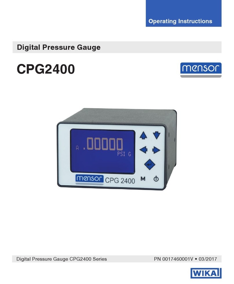
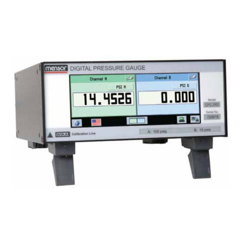
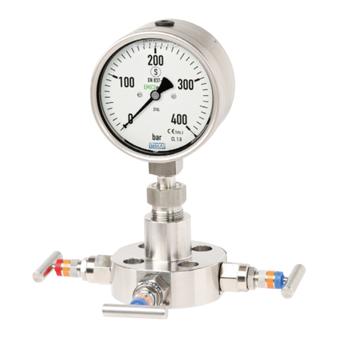
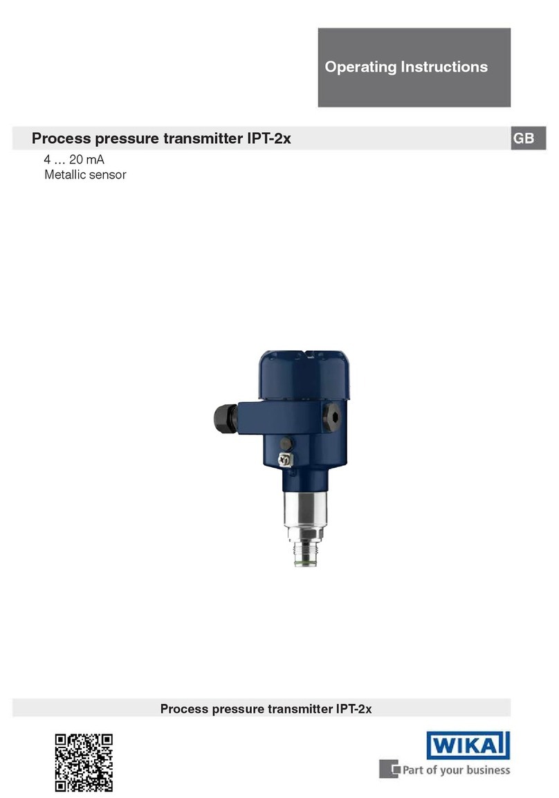
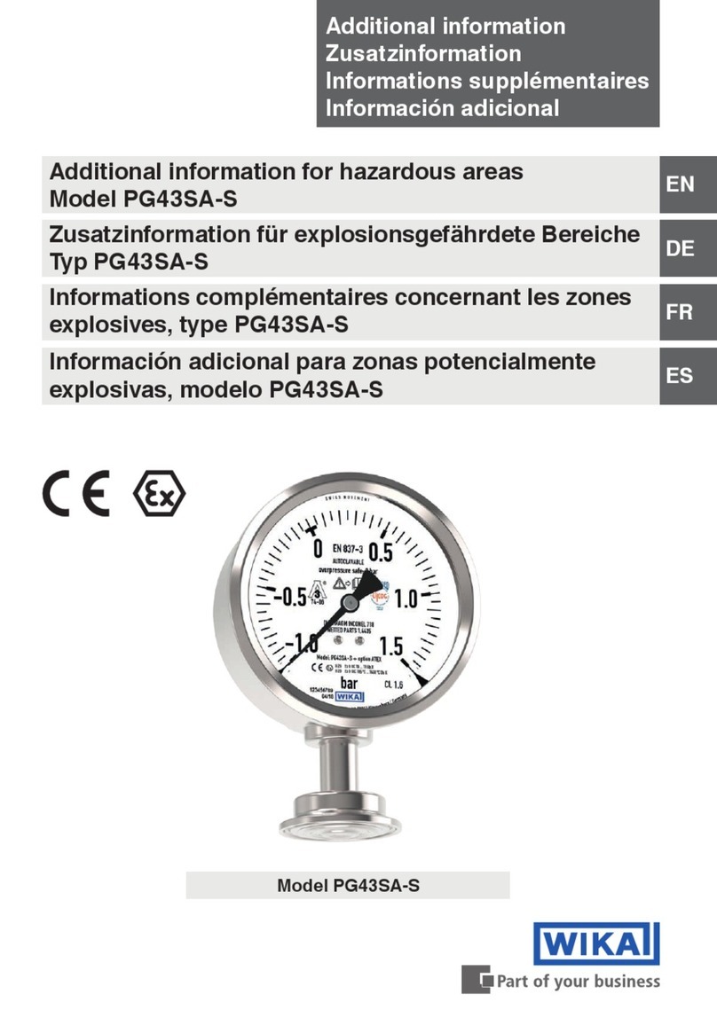
WIKA 1500 Series User manual

Book # 52090680 Page 1
WIKA INSTRUMENT CORPORATION
Instruction Manual
Absolute Pressure Gauge
Series 1500
Series 1000
Series 300
WIKA Instrument Corporation
1000 Wiegand Boulevard
Lawrenceville, GA 30043
1-888-945-2872
http://www.wika.com
PLEASE NOTE: THIS EQUIPMENT HAS BEEN DESIGNED TO PROVIDE RELIABLE SERVICE;
HOWEVER, BEFORE ATTEMPTING TO INSTALL, OPERATE OR SERVICE THE EQUIPMENT, THIS
INSTRUCTION MANUAL MUST BE READ, UNDERSTOOD AND OBSERVED. FAILURE TO DO SO CAN
RESULT IN IMPROPER OPERATION WITH POSSIBLY HAZARDOUS CONSEQUENCES.

Book # 52090680 Page 2
VERY IMPORTANT SAFETY PRECAUTIONS
This page provides in brief, information of urgent importance relative to SAFETY in the INSTALLATION & OPERATION of this equipment.
WARNING
TO AVOID POSSIBLE SEVERE PERSONAL INJURY, DO NOT EXCEED THE MAXIMUM CASE WORKING PRESSURE. EXCESSIVE PRESSURE MAY
RUPTURE THE GLASS DIAL COVER.
TO ENSURE PROPER AND SAFE OPERATION OF THIS EQUIPMENT, USE ONLY WIKA LISTED PARTS EXCEPT COMMERCIALLY AVAILABLE PARTS AS
IDENTIFIED BY COMPLETE DESCRIPTION ON PARTS LIST. THE USE OF UNLISTED PARTS CAN RESULT IN EQUIPMENT MALFUNCTIONS CAUSING
POSSIBLE SEVERE PERSONAL INJURY.
DO NOT DISCARD THIS INSTRUCTION BOOK UPON COMPLETION OF INSTALLATION. INFORMATION PROVIDED IS ESSENTIAL TO PROPER AND
SAFE OPERATION AND MAINTENANCE.
ADDITIONAL OR REPLACEMENT COPIES OF THIS INSTRUCTION BOOK ARE AVAILABLE FROM:
WIKA Instrument Corporation
1000 Wiegand Boulevard
Lawrenceville, GA 30043 USA
Tel (888) WIKA-USA (888-945-2872)
FAX (770) 338-5118
________________________________________________________________________________________________________________
NOTE
Minor part number changes may be incorporated into WIKA products from time to time that are not immediately reflected in the instruction
book. If such a change apparently has been made in your equipment and does not appear to be reflected in your instruction book, contact your
local WIKA sales office for information.
Please include the equipment serial number in all correspondence for effective communication and proper equipment identification.

Book # 52090680 Page 3
INTRODUCTION
This instruction book provides installation, operation and maintenance instructions for the WIKA Absolute Pressure Gauges Series 1500, Series 1000 and
Series 300.
WARNING: TO AVOID POSSIBLE SEVERE PERSONAL INJURY OR DAMAGE TO THE EQUIPMENT, THIS EQUIPMENT SHOULD BE INSTALLED,
OPERATED AND SERVICED ONLY BY TRAINED, QUALIFIED PERSONNEL WHO ARE THOROUGHLY FAMILIAR WITH THE ENTIRE CONTENTS OF
THIS INSTRUCTION BOOK.
WARNING: IMPROPER USE OF THIS GAUGE MAY CAUSE EXPLOSION AND PERSONAL INJURY. READ INSTRUCTION BOOK BEFORE USING THIS
EQUIPMENT.
General and Safety related information on the installation and use of pressure gauges should be followed. ASME B40.100 latest standards should be
referenced as a guideline. A complete standard may be obtained from the AMERICAN SOCIETY OF MECHANICAL ENGINEERS; ASME, Three Park Avenue,
New York, NY 10016-5990,800-843-2763 (US/Canada), 973-882-1170 (outside North America), website: www.asme.org.
INSTALLATION
Protect the instrument from shock and vibration. In some cases it may be necessary to provide shock mounted panels. Select a location to provide a
minimum change in temperature. Avoid locations adjacent to heating units or otherwise subject to temperature changes. Access to pressure
connections is required if the filter is to be removed for cleaning (see Maintenance). The protective check valve, if furnished, must not be removed.
Dimension drawings will be found in the back of this book.
OPERATION
Over-Pressure Precautions
For best performance do not subject any of these instruments to pressures above their ranges.
Series 1500 and Series 1000 Gauges
Pressure in excess of 110% of full scale range may distort the mechanism.
On ranges of 50 psia and below, the system pressure is applied to the inside of the case (see Dwg.610.050.170.011). The maximum case working
pressure of 35 psig is stated on the dial.
WARNING: TO AVOID POSSIBLE SEVERE PERSONAL INJURY, DO NOT EXCEED THIS PRESSURE. EXCESSIVE PRESSURE MAY RUPTURE THE GLASS
DIAL COVER.
On the above ranges, case relief valves have been provided as an integral part of the case back. These are emergency-protective devices only. Systems
should be designed and operated to limit the case pressure to 35 psig or 110% of full scale whichever is lower.
NOTE: Do not tamper with the pressure relief valve.
These valves have dumping capacities which protect the case from applied pressures up to 60 times the case rating.
On ranges above 50 psia, the system pressure is applied to the inside of the bourdon tube (see Dwg.610.050.170.021). Plastic blow-out plugs are
provided in the back of the case. In the event of accidental rupture of the bourdon tube, these plugs will blowout at less than 5 psig thus venting the
case to atmosphere.
Series 300 Gauges
The system pressure is applied to the inside of the instrument case (see Dwg.610.050.170.011). The maximum case working pressure is stated on the
dial: 15 psig for the 6-inch diameter dial gauge and 150 psig for the 2-3/4-inch diameter dial gauge.
WARNING: TO AVOID POSSIBLE SEVERE PERSONAL INJURY, DO NOT EXCEED THIS PRESSURE. EXCESSIVE PRESSURE MAY RUPTURE THE GLASS
DIAL COVER.
Series 300 gauges do not have built in pressure relief devices. Optional valves are available (see Dwg.610.050.100.011 and 610.050.100.021).
If there is any possibility of the system pressure exceeding the maximum case pressure specified on the dial, install adequate relief or pressure shut-off
valves.
Gauges with ranges less than one atmosphere (15 psia) have protective check valves FU3229 installed (see Dwgs.610.050.100.011 and 610.050.100.021).
These valves will protect the gauge mechanism against sudden release of vacuum or sudden surge of pressure.

Book # 52090680 Page 4
NOTE: The check valves are not intended to be overpressure protection devices.
CAUTION: Do not operate gauges without check valve. Gauge may be damaged if operated without the protective check valve.
6-inch Diameter Dial Gauges
The maximum case working pressure is 15 psig.
Gauges with ranges less than one atmosphere (15 psia) will withstand pressure up to 4 psig without damaging the mechanism.
Gauges with one atmosphere range will withstand 150% of full scale or approximately 22 psia (7 psig) without mechanism distortion.
On gauges with range of 30 psia, do not exceed full scale (approximately 15 psig) since this is the maximum working pressure for the case.
2-3/4-inch Diameter Dial Gauge
The maximum case working pressure is 150 psig.
Gauges with ranges less than one atmosphere will withstand pressure up to 4 psig without damaging the mechanism.
All ranges of one atmosphere and above will withstand 150% of full scale pressure without damaging the mechanism.
Exercising: Before the instrument is used for precise measurements, exercise it by alternately increasing and decreasing the applied pressure over the
entire range of the instrument at least three times. Hold maximum and minimum pressures for two minute periods.
Reading: Unless otherwise noted, the instrument is calibrated to be read with the dial in the vertical position. When the instrument has a mirror on the
dial, the pointer and its image should coincide so that only the pointer may be seen. On two revolution instruments, an indicator shows the portion of
the scale to be read.
All WIKA High Precision instruments are calibrated on increasing pressure. To avoid any effect of hysteresis, take readings on increasing pressure.
Instruments are calibrated at 23⁰C. Unless wide temperature changes are experienced, the effect of temperature may be neglected. For further
discussion, see CALIBRATION CHECK.
CALIBRATION CHECK
A complete check of calibration of an instrument requires that it be exercised as above and compared with a standard having a verified accuracy several
times greater and a scale comparable in length to the instrument being checked. The standard must be corrected for all its inherent errors and must be
corrected to standard conditions of gravity (980.665 cm/sec²) and temperature (O⁰C for mercury columns or 20⁰C for water columns, where applicable).
While aneroid instruments are not subject to changes in reading due to gravity they are affected by temperature. WIKA High Precision instruments read
directly in terms of standard conditions (see preceding paragraph) at a temperature of 23°C unless other-wise indicated. If the calibration check is
conducted at 23°C, the effect of temperature, on the WIKA instrument need not be considered. At any other temperature, the temperature effect listed
in the table PERFORMANCE CAPABILITY must be considered. This is not a correction factor but rather, a tolerance that must be added to other
tolerances being checked. When readings are taken on increasing pressures, they should fall within the specified reading accuracy tolerance given in the
table. The difference between the up-scale reading and the down-scale reading is the hysteresis error and should fall within the specified limits.
Setting the pointer If a calibration check shows the readings on increasing pressures at various points over the entire range are out by the same angular
distance, the pointer may be reset. Adjustment is limited to a pointer movement of about 10 degrees.
Access locations to the pointer adjustment screw are described in the following text.
If the error is not linear and cannot be corrected with a simple pointer adjustment, the gauge should be returned to the factory for repair and/or
recalibration.
WIKA maintains a fully equipped service center staffed with trained personnel to repair and recalibrate WIKA instruments.
Series 1000 and 1500 have two different adjustment locations: on ranges below 100 psig, access to the pointer adjustment is obtained by removing a
screw in the rear of the case. On ranges 100 psig and over the adjustment is done by removing a screw in the glass dial cover (see DWG 610.050.101.011
and 610.050.102.011).
Adjustment of Series 300 During operation of the instrument under a high vacuum source if the pointer reads above zero, check the system for
tightness. Necessity for adjustment may be determined by placing the instrument in a system as close to the vacuum source as possible and evacuating
for a period of one hour. A pointer adjustment, if required, may be made by using the bezel FU4252 for the 2-3/4-inch dial instrument or the bezel
FU2542 for the 6-inch dial instruments.
1. Disconnect the instrument from the vacuum source.
2. Remove the bezel and glass from the instrument.
Book # 52090680 Page 5
PERFORMANCE CAPABILITY
SERIES
ACCURACY (1)
SENSITIVITY (1)
HYSTERISIS(1)
MAX. TEMP EFFECTS (2)
1500
0.066
0.01
0.015 ( 3)
0.019 (3)
0.1 (4)
0.1 (4)
1000
0.1
0.01
0.15 (3)
0.019 (3)
0.1 (4)
0.1 (4)
300
0.3
0.2
—
—
3. Put the gasket in the groove. Install the special bezel and tighten all screws evenly.
4. Evacuate the instrument for one hour. Push in on the screwdriver to engage the adjusting screw. The pointer will rotate in the direction the
screwdriver is turned.
5. After the pointer is set t remove the special bezel and replace the instrument bezel and glass.
6. Evacuate the instrument for one hour and read to be sure that the instrument is tight.
If the special bezel is not available, the correction must be made by the trial and error method. The range of correction is approximately 10 degrees. It is
important that the gasket be properly placed to obtain tightness of the case. When the gasket is improperly replaced, a leak will develop. A correction
made without comparison against a standard may be compensating for a leak rather than a gauge error.
MAINTENANACE
Filter Each instrument is furnished with a filter screwed into the pressure connections. The filter screen may occasionally require cleaning. This may be
done as follows:
1. Unscrew the filter plug by means of a screwdriver.
2. Clean the filter with detergent and hot water or other suitable solvent. Reinstall the filter.
Lubrication The mechanism does not require oil. The oil will interfere with the proper functioning and introduce serious errors.
NOTE: Do not oil the mechanism
NOTES:
(1) %Full Scale. "Full scale" is the difference between minimum and maximum dial reading. "'Full scale" of an instrument with a calibrated
range of 0 to 800 ram Hg is 800 mm Hg whereas "full scale" of an instrument with a calibrated range of 390 to 800 mm Hg is 410 mm Hg.
(2) % Full Scale per 10°C from 23°C.
(3) Below 100 psia
(4) 100 psia and above
WARNING LABEL:
The following warning label has been attached to the equipment and is listed below:
L2326: IMPROPER USE OF THIS GAUGE MAY CAUSE EXPLOSION & PERSONAL INJURY. READ INSTRUCTION BOOK BEFORE USING THIS EQUIPMENT,
CAUTION LABEL
The following caution label has been attached to the equipment and is listed below:
L2060: DO NOT OPERATE GAUGE WITHOUT CHECK VALVE.

Book # 52090680 Page 6
SERIES 1500 BELOW 100 P.S.I.A.
SERIES 1000 BELOW 100 P.S.I.A.
SERIES 300 ALL RANGES
DWG: 610.050.170.011
PRESSURE RELIEF VALVE:
(ON SERIES 1000 AND 1500 ONLY)
(BACK OF CASE)
SYSTEM PRESSURE
APPLIED INTO CASE
(DO NOT EXCEEO MAX. PRESSURE
NOTED ON DIAL)
PRESSURE SENSITIVE
ELEMENT SEALED AT
ZEAO ABSOLUTE
PRESSURE
ABSOLUTE PRESSURE GUAGE
OPERATION

Book # 52090680 Page 7
DWG: 610.050.170.021
ABSOLUTE PRESSURE GUAGE
OPERATION

Book # 52090680 Page 8

Book # 52090680 Page 9

Book # 52090680 Page 10

Book # 52090680 Page 11
Other manuals for 1500 Series
1
This manual suits for next models
2
Table of contents
Other WIKA Measuring Instrument manuals

WIKA
WIKA 232.30.100 Operating instructions

WIKA
WIKA 831 User manual

WIKA
WIKA 821 User manual

WIKA
WIKA 632.50.100 User manual

WIKA
WIKA DG-05 User manual

WIKA
WIKA intelliTHERM TGT70 User manual

WIKA
WIKA 4 User manual

WIKA
WIKA FLC-UFL Series User manual

WIKA
WIKA mensor 9476 User manual

WIKA
WIKA 891.34 User manual