WIKA 1/4000 User manual

ES
FR
DE
EN
Operating instructions
Betriebsanleitung
Mode d'emploi
Manual de instrucciones
Resistance thermometer TR10-0 and thermocouple TC10-0
Ignition protection type FP (Ex d) and XP (class/division)
Widerstandsthermometer TR10-0 und Thermoelement TC10-0
Zündschutzart FP (Ex d) und XP (Klasse/Division)
Sonde à résistance TR10-0 et thermocouple TC10-0
Type de protection contre l’ignition FP (Ex d) et XP (classe/division)
Termorresistencia TR10-0 y termopar TC10-0
Tipo de protección FP (Ex d) y XP (clase/división)
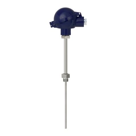
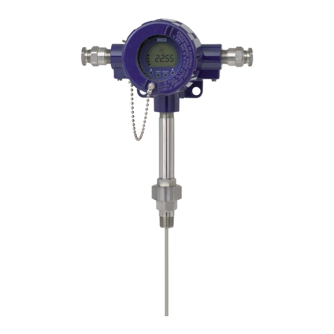
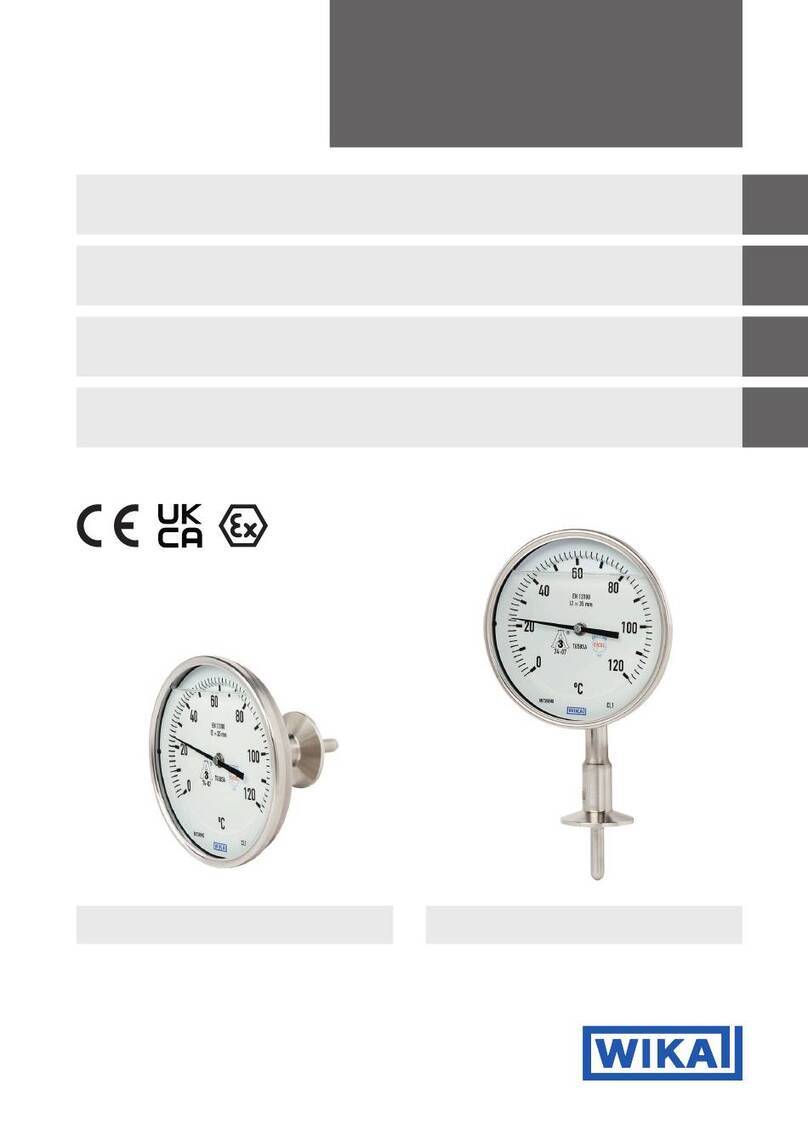
Connection head 1/4000 Connection head 7/8000
1182963 FM17US0254X

2
EN
DE
ES
FR
Operating instructions models TR10-0, TC10-0
Page 3 - 22
Betriebsanleitung Typen TR10-0, TC10-0
Seite 23 - 42
Mode d'emploi types TR10-0, TC10-0
Page 43 - 62
Manual de instrucciones modelos TR10-0, TC10-0
Página 63 - 82
WIKA operating instructions models TR10-0, TC10-0 (FM, CSA)
14503941.01 11/2021 EN/DE/FR/ES
© 11/2021 WIKA Alexander Wiegand SE & Co. KG
All rights reserved. / Alle Rechte vorbehalten.
WIKA®is a registered trademark in various countries.
WIKA®ist eine geschützte Marke in verschiedenen Ländern.
Prior to starting any work, read the operating instructions!
Keep for later use!
Vor Beginn aller Arbeiten Betriebsanleitung lesen!
Zum späteren Gebrauch aufbewahren!
Lire le mode d‘emploi avant de commencer toute opération !
A conserver pour une utilisation ultérieure !
¡Leer el manual de instrucciones antes de comenzar cualquier trabajo!
¡Guardar el manual para una eventual consulta!

1. General information 4
2. Design and function 4
3. Safety 6
4. Transport, packaging and storage 9
5. Commissioning, operation 10
6. Information on mounting and operation in hazardous areas 13
7. Safety-related instructions 14
8. Faults 16
9. Maintenance, cleaning and recalibration 18
10. Dismounting, return and disposal 19
11. Specifications 20
WIKA operating instructions models TR10-0, TC10-0 (FM, CSA)
14503941.01 11/2021 EN/DE/FR/ES
3
EN
Contents
Contents

14503941.01 11/2021 EN/DE/FR/ES
4WIKA operating instructions models TR10-0, TC10-0 (FM, CSA)
EN
1. General information
■
The instrument described in the operating instructions has been manufactured
using state-of-the-art technology. All components are subject to stringent quality and
environmental criteria during production. Our management systems are certied to
ISO 9001 and ISO 14001.
■
These operating instructions contain important information on handling the instrument.
Working safely requires that all safety instructions and work instructions are observed.
■
Observe the relevant local accident prevention regulations and general safety regulations
for the instrument's range of use.
■
The operating instructions are part of the product and must be kept in the immediate
vicinity of the instrument and readily accessible to skilled personnel at any time.
■
Skilled personnel must have carefully read and understood the operating instructions
prior to beginning any work.
■
The manufacturer's liability is void in the case of any damage caused by using the
product contrary to its intended use, non-compliance with these operating instructions,
assignment of insuciently qualied skilled personnel or unauthorised modications to
the instrument.
■
The general terms and conditions contained in the sales documentation shall apply.
■
Subject to technical modications.
■
Further information:
- Internet address: www.wika.de / www.wika.com
- Relevant data sheet: TE 61.01 (TR10-0), TE 66.01 (TC10-0)
- Application consultant: Tel.: +49 9372 132-0
Fax: +49 9372 132-406
info@wika.de
2. Design and function
2.1 Description
The model TR10-0 (resistance thermometer) or TC10-0 (thermocouple) electrical
thermometers are comprised of a measuring insert which is built into a certied case. In
combination with a ame path tting that is screwed into the head, the measuring insert
functions as a ameproof joint. The measuring insert (TR10-1, TC10-1) is replaceable.
Sensor design in model TR10-0
The measuring resistor is embedded in ceramic powder, heat-resistant potting compound,
cement compound or thermally conductive paste. A welded cap forms the external shell of
the sensor tip of the measuring insert.
1. General information / 2. Design and function

WIKA operating instructions models TR10-0, TC10-0 (FM, CSA)
14503941.01 11/2021 EN/DE/FR/ES
5
EN
Sensor design in model TC10-0
The measuring insert of the thermocouple is manufactured from mineral-insulated cable.
The thermocouple consists of the internal leads of the mineral-insulated cable.The weld
spot of the thermocouple is, depending on the design, either ungrounded welded with the
internal leads of the mineral-insulated cable or grounded welded.
If the temperature sensor is designed as a grounded thermocouple, the thermocouple is
joined directly to the sheath. Designs with a diameter smaller than 3 mm and with grounded
thermocouples should be considered as galvanically connected with earth potential.
Available versions:
■
Flame path without thermowell
■
Flame path with thermowell
■
Thermometers without a ame path tting may be designed as a welded bushing without
thermowell
Thermometers without a ame path tting may only be used in combination with a solid-
machined, certied WIKA thermowell with a minimal wall thickness of 1 mm.
After installation of a ame path tting into the connection head of the thermometer, a
thermowell is no longer mandatory for certication reasons. In most cases, however, the
use of a thermowell (with a wall thickness of 1 mm) is necessary for process engineering
reasons.
The design of the thermowell can be selected as desired, but the operational process
data (temperature, pressure, density and ow rate) must be taken into account. If a WIKA
thermowell is already available or installed, a ame path tting is not necessary.
The thermometers models TR10-0 or TC10-0 are manufactured by WIKA with certied
connection heads or connection housings.These enclosures and covers are made from
aluminium or stainless steel.The cover is optionally available with a glass window.
Possible sensor measuring ranges see chapter 11 “Specications”
The following mounting and operating information has been compiled with care.
However, it is not possible to consider all potential usage cases.
2.2 Scope of delivery
Cross-check scope of delivery with delivery note.
2. Design and function

14503941.01 11/2021 EN/DE/FR/ES
6WIKA operating instructions models TR10-0, TC10-0 (FM, CSA)
EN
3. Safety
3.1 Explanation of symbols
WARNING!
... indicates a potentially dangerous situation that can result in serious injury or
death, if not avoided.
CAUTION!
... indicates a potentially dangerous situation that can result in light injuries or
damage to property or the environment, if not avoided.
WARNING!
... indicates a potentially dangerous situation in the hazardous area that can
result in serious injury or death, if not avoided.
WARNING!
... indicates a potentially dangerous situation that can result in burns, caused
by hot surfaces or liquids, if not avoided.
Information
... points out useful tips, recommendations and information for ecient and
trouble-free operation.
3.2 Intended use
These resistance thermometers and thermocouples are used for temperature measurement
in industrial applications, in hazardous areas.
The instrument has been designed and built solely for the intended use described here, and
may only be used accordingly.
The technical specications contained in these operating instructions must be observed.
Improper handling or operation of the instrument outside of its technical specications
requires the instrument to be taken out of service immediately and inspected by an
authorised WIKA service engineer.
The manufacturer shall not be liable for claims of any type based on operation contrary to
the intended use.
3. Safety

WIKA operating instructions models TR10-0, TC10-0 (FM, CSA)
14503941.01 11/2021 EN/DE/FR/ES
7
EN
3.3 Responsibility of the operator
The system operator is responsible for selecting the thermometer or thermowell, and for
the selection of their materials, so as to guarantee their safe operation within the plant or
machine.When preparing a quote, WIKA can only give recommendations which are based
on our experience in similar applications.
The safety instructions within these operating instructions, as well as the safety, accident
prevention and environmental protection regulations for the application area must be
maintained.
The operator is obliged to maintain the product label in a legible condition.
3.4 Personnel qualification
WARNING!
Risk of injury should qualication be insucient
Improper handling can result in considerable injury and damage to property.
▶The activities described in these operating instructions may only be carried
out by skilled electrical personnel who have the qualications described
below.
Skilled personnel
Skilled personnel are understood to be personnel who, based on their technical training,
knowledge of measurement and control technology and on their experience and knowledge
of country-specic regulations, current standards and directives, are capable of carrying out
the work described and independently recognising potential hazards.
Special operating conditions require further appropriate knowledge, e.g. of aggressive
media.
3. Safety

14503941.01 11/2021 EN/DE/FR/ES
8WIKA operating instructions models TR10-0, TC10-0 (FM, CSA)
EN
3.5 Labelling, safety marking
Product label (example)
Model
Serial number
Information on version (measuring element, measuring range ...)
Sensor in accordance with standard (thermocouple)
■
ungrounded
■
grounded
Transmitter model (only for design with transmitter)
Year of manufacture
Approval-related data
Sensor symbol
■
ungrounded = ungrounded welded
■
grounded = welded to the sheath (grounded)
■
quasi grounded = The thermometer is, due to its low insulation clearances between resistance
sensor and sheath, to be considered as grounded.
■
Additional information for Ex instruments
■
Product label for Tx10-1
(replacement measuring insert)
TR10-B
1 x Pt100 / B / 3 (F) -50 ... +250 °C
IEC 60751
Made in Germany
2014
1102AB12
T32.1S.0NI 4 ... 20 mA -50 ... +250 °C
D-63911 Klingenberg
HART ®
TR10-A-IICZ
1102AB12
1 x Pt100 / B / 3
-50 ... +250 °C
D = 6 mm
525 mm
(F)
D-63911 Klingenberg
IEC 60751
II 3G Ex nA IIC T1 ... T6 Gc X
WARNING! DO NOT OPEN WHILE ENERGISED!
II 3G Ex nA IIC T1 ... T6 Gc X
II 3D Ex tc IIIC T440°C ... T80°C Dc X
Tamb T6/T5/T4-T1: -20 ... +55/+70/+80 °C
Tamb T80/95/130-440°C: -20 ... +55/+70/+80 °C
L = 1 µH/m, C = 200 pF/m
Made in Germany 2014
WARNING! POTENTIAL ELECTROSTATIC CHARGING HAZARD!
II 3G Ex nA IIC T1 ... T6 Gc X
II 3D Ex tc IIIC T440°C ... T80°C Dc X
Tamb T6/T5/T4-T1: -20 ... +55/+70/+80 °C
Tamb T80/95/130-440°C: -20 ... +55/+70/+80 °C
L = 1 µH/m, C = 200 pF/m
Ex n / Ex d
Ex i
EAC (landesspezifisches Zusatzschild)
ΒΗИМАНИЕ!
ПОТЕНЦИАЛЬНЫЙ РИСК НАКОПЛЕНИЯ
ЭЛЕКТРОСТАТИЧЕСКОГО ЗАРЯДА!
СДЕЛАНО В ГЕРМАНИИ
3. Safety
WIKA operating instructions models TR10-0, TC10-0 (FM, CSA)
14503941.01 11/2021 EN/DE/FR/ES
9
EN
Before mounting and commissioning the instrument, ensure you read
the operating instructions!
4. Transport, packaging and storage
4.1 Transport
Check the instrument for any damage that may have been caused by transport.
Obvious damage must be reported immediately.
CAUTION!
Damage through improper transport
With improper transport, a high level of damage to property can occur.
▶When unloading packed goods upon delivery as well as during internal
transport, proceed carefully and observe the symbols on the packaging.
▶With internal transport, observe the instructions in chapter 4.2 “Packaging
and storage”.
If the instrument is transported from a cold into a warm environment, the formation of
condensation may result in instrument malfunction. Before putting it back into operation, wait
for the instrument temperature and the room temperature to equalise.
4.2 Packaging and storage
Do not remove packaging until just before mounting. Keep the packaging as it will provide
optimum protection during transport (e.g. change in installation site, sending for repair).
Permissible conditions at the place of storage:
■
Storage temperature: -40 ... +80 °C [-40 ... +176 °F]
■
Humidity: 35 ... 85 % relative humidity (no condensation)
Avoid exposure to the following factors:
■
Direct sunlight or proximity to hot objects
■
Mechanical vibration, mechanical shock (putting it down hard)
■
Soot, vapour, dust and corrosive gases
■
Hazardous environments, ammable atmospheres
Store the instrument in its original packaging in a location that fulls the conditions listed
above. If the original packaging is not available, pack and store the instrument as described
below:
1. Place the instrument along with shock-absorbent material in the packaging.
2. If stored for a prolonged period of time (more than 30 days), place a bag containing a
desiccant inside the packaging.
3. Safety / 4. Transport, packaging and storage

14503941.01 11/2021 EN/DE/FR/ES
10 WIKA operating instructions models TR10-0, TC10-0 (FM, CSA)
EN
5. Commissioning, operation
5.1 Removal and installation of the measuring insert
When servicing or recalibrating is necessary, make sure that both surfaces of the ameproof
joint (ame path tting and measuring insert) are not damaged when installing the
measuring insert. Damaged or scratched parts of the ameproof joint must be replaced.
5.2 Electrical connection
5.2.1 Connection to terminal block
Model TR10-0
Assignment and colour coding for Pt1000 as well as for Pt100
Pt1000 only available as single elements
red
1 x Pt100, 2-wire 1 x Pt100, 3-wire 1 x Pt100, 4-wire
white white
red
red
red
red
white
white
white white white
white
red
red red
red
red
2 x Pt100, 2-wire 2 x Pt100, 3-wire 2 x Pt100, 4-wire
red white white red
red
white
black yellow yellow
yellow
black
black
white
white
red
red
red
red
black
black
black
black
yellow yellow
yellow
red
white
black
yellow
white
5. Commissioning, operation

WIKA operating instructions models TR10-0, TC10-0 (FM, CSA)
14503941.01 11/2021 EN/DE/FR/ES
11
EN
Model TC10-0
5.2.2 Connection to built-in transmitter
For the electrical specications (e.g. connection diagrams, tolerance values, etc.) please
refer to the relevant operating instructions and/or data sheet for the built-in head-mounted
transmitter.
Junction between cable and appropriate conduit/sealing tting:
Screw the male nut tightly into the adapter (use appropriate tools!)
During installation, take care to
■
Avoid distorting the cable sheath when tightening the male nut.
■
Avoid cutting too deep into the cable sheath.
■
Use suitable cable/conduit.
■
Be careful of the clamping zone of the conduit/sealing tting.
Refer to NEC/CEC for additional information.
Single thermocouple Dual thermocouple
The colour coding at
the positive poles of the
instrument decides the
correlation of polarity
and terminal.
3166822.03
5. Commissioning, operation

14503941.01 11/2021 EN/DE/FR/ES
12 WIKA operating instructions models TR10-0, TC10-0 (FM, CSA)
EN
5.3 Tightening torques
Connection head, selectable (example)
Thread Tightening torques
1/2 NPT T.F.F.T. 2 - 3 1)
3/4 NPT T.F.F.T. 2 - 3 1)
G 1/2 B 35 Nm
G 3/4 B 40 Nm
M14 x 1.5 25 ... 30 Nm
M18 x 1.5 35 Nm
M20 x 1.5 35 ... 40 Nm
M27 x 2 40 ... 45 Nm
1) Turns from nger tight (T.F.F.T.)
Tightening torques for connection to thermowell
■
Only ever screw in, or unscrew, the instrument via the spanner ats and to the prescribed
torque using an appropriate tool.
■
The correct torque depends on the dimensions of the connection thread and the gasket
used (form/material).
■
Screwing or unscrewing the connection head is not permitted.
■
When screwing in the instrument, please observe that the threads are not skewed.
5. Commissioning, operation
5.4 Locking screw
Always tighten the locking screw to prevent unintended opening of
the head with ameproof enclosure.
Before opening the head, always loosen the locking screw
suciently.

WIKA operating instructions models TR10-0, TC10-0 (FM, CSA)
14503941.01 11/2021 EN/DE/FR/ES
13
EN
6. Information on mounting and operation in hazardous areas
WARNING!
Non-observance of these instructions and their contents may result in the loss
of explosion protection.
The requirements of CSA and FM must be followed. Additionally the
specications of the respective national regulations concerning usage (e.g.
CEC and NEC) apply.
■
The responsibility for area classication lies with the plant operator and not the
manufacturer/supplier of the equipment.
■
The plant operator guarantees, and is solely responsible, that all thermometers in use
are identiable with respect to all safety-relevant characteristics. Damaged thermometers
may not be used.
■
For the installation of the thermometer, only components (e.g. cables, cable glands, etc.)
permitted for “ameproof” may be used.
■
For earthing the conductive screen, follow the specications of CEC or NEC.
■
When using a transmitter/digital display, note and follow:
- The contents of these operating instructions and those of the transmitter/digital display
- The relevant regulations for installation and use of electrical systems
- The regulation and guidelines regarding explosion protection
■
The ameproof thermometers should only be tted to certied enclosure or connection
heads certied with a “ameproof” ignition protection type.
■
For tting, the permitted ameproof joints for electrical equipment for gas hazardous
areas are contained in CSA C22.2 No. 30, CSA 60079-1 and FM 3615.
■
The direct threaded connection of the thermometer to the connection head or enclosure
must not be twisted or opened. Any alignment of the enclosure may only be made using
the optional “nipple-union-nipple” neck tube.
■
The temperature resistance of the connection cable must match the permissible
operating temperature of the enclosure. For ambient temperatures above 60 °C [140 °F],
heat-resistant connection cable must be used.
■
No batteries may be built in to the ameproof enclosure.
■
No capacitor may be tted within the ameproof enclosure.The enclosure must not be
opened during operation. After the supply voltage has been switched o, a waiting time of
2 minutes must be observed before the enclosure is opened.
■
Mounting within metal enclosures:
The enclosure must be grounded against electromagnetic elds and electrostatic
discharge. It does not have to be connected separately to the equipotential bonding
system. It is sucient if the metal thermowell has a solid and secured contact with the
metal vessel or its structural components or pipelines, so long as these components are
connected to the equipotential bonding system.
6. Information on mounting and operation in hazardous areas

14503941.01 11/2021 EN/DE/FR/ES
14 WIKA operating instructions models TR10-0, TC10-0 (FM, CSA)
EN
■
Neither repairs nor structural modications are permitted, and any would void the
guarantee and the respective certication.
■
The manufacturer shall not be responsible for constructional modications after delivery
of the instruments.
7. Safety-related instructions
7.1 Marking
Design CSA FM
Class/Division Zone Class/Division
Without flame path
with thermowell
(minimum wall
thickness 1 mm)
Class I, division 1, groups
B, C, D
Class II, groups E, F, G
Class III
Enclosure type 4 or 4X
CAN zones FP: Ex d IIC Gb T6/
T5/T4
Class I, division 1,
groups B, C, D
Class II, groups E, F, G
Class III
Enclosure type 4 or 4X
USA zones FP: Class I, zone 1,
AEx d IIC Gb T6/T5/T4
With flame path
with protection tube
(minimum wall
thickness 1 mm)
Class I, division 1, groups
B, C, D
Class II, groups E, F, G
Class III
Enclosure type 4 or 4X
CAN zones FP: Ex d IIB+H2 Gb
T6/T5/T4
Class I, division 1,
groups B, C, D
Class II, groups E, F, G
Class III
Enclosure type 4 or 4X
USA zones FP: Class I, zone 1,
AEx d IIB+H2 Gb T6/T5/T4
With flame path
without thermowell
Class I, division 1, groups
B, C, D
Class II, groups E, F, G
Class III
Enclosure type 4 or 4X
CAN zones FP: Ex d IIB+H2 Gb
T6/T5/T4
Class I, division 1,
groups B, C, D
Class II, groups E, F, G
Class III
Enclosure type 4 or 4X
USA zones FP: Class I, zone 1,
AEx d IIB+H2 Gb T6/T5/T4
Welded bushing Class I, division 1, groups
B, C, D
Class II, groups E, F, G
Class III
Enclosure type 4 or 4X
CAN zones FP: Ex d IIC Gb T6/
T5/T4
Class I, division 1,
groups B, C, D
Class II, groups E, F, G
Class III
Enclosure type 4 or 4X
USA zones FP: Class I, zone 1,
AEx d IIC Gb T6/T5/T4
Electrical parameters
Maximum DC 30 V, 20 mA
6. Information on mounting ... / 7. Safety-related instructions

WIKA operating instructions models TR10-0, TC10-0 (FM, CSA)
14503941.01 11/2021 EN/DE/FR/ES
15
EN
7. Safety-related instructions
7.2 Special conditions for safe use
1. The ambient temperature limits are:
CSA, T6: -50 ... +60 °C [-58 ... +140 °F]
CSA, T5: -50 ... +75 °C [-58 ... +167 °F]
CSA, T4: -50 ... +85 °C [-58 ... +185 °F]
FM class/division, T6: -25 ... +40 °C [-13 ... +104 °F]
2. Care shall be taken to ensure that any external sources of heating or cooling do not cause
the assembly to operate outside of the allowable ambient temperature range.
3. All cable entry devices shall be suitably certied and compatible with the type of
protection used.
4. Where nipples, unions and/or couplers are used for sensor connections, they shall be
suitably certied and be compatible with the marking of this assembly. Nipples shall have
a maximum length ≤ 15.24 cm [6 in].
5. For ambient temperatures above 70 °C [158 °F], care shall be taken to select cable that is
suitably rated for the intended ambient temperature range.
Thermowell
(minimum wall thickness 1 mm)
Protection tube
(minimum wall thickness 1 mm)
Without thermowell/
protection tube
Legend:
Connection head
Neck tube
Connection to thermowell/protection tube
Measuring insert
Process connection
Terminal block/transmitter
Flame path tting
14081546.01
Welded bushing
welded

14503941.01 11/2021 EN/DE/FR/ES
16 WIKA operating instructions models TR10-0, TC10-0 (FM, CSA)
EN
Temperature class classication, ambient temperatures
A heating in the connection head can occur with built-in transmitter through faulty
electronics.The permissible ambient temperatures depend on the cases used and any
additionally tted head-mounted transmitter.
For all WIKA connection heads with built-in WIKA temperature transmitters, the
following interrelation is valid:
The temperature increase on the surface of the connection head or case is less than 25 K
if the following conditions are observed: supply voltage UBmaximum DC 30 V when the
transmitter is operated in a current limit of 22.5 mA.
The temperature class is dependent upon the user application and the ambient temperature.
The permissible ambient temperatures for third-party products can be seen from the relevant
approvals and/or data sheets. However, an impermissible heat reux from the process
which can exceed the operating temperature of the case or the temperature class, must be
prevented through suitable heat insulation or a suitably long neck tube.
8. Faults
DANGER!
Danger to life from explosion
Through working in ammable atmospheres, there is a risk of explosion which
can cause death.
▶Only rectify faults in non-ammable atmospheres!
CAUTION!
Physical injuries and damage to property and the environment
If faults cannot be eliminated by means of the listed measures, the instrument
must be taken out of operation immediately.
▶Ensure that there is no longer any signal present and protect against being
put into operation accidentally.
▶Contact the manufacturer.
▶If a return is needed, please follow the instructions given in chapter 10.2
“Return”.
For contact details, please see chapter 1 “General information” or the back
page of the operating instructions.
7. Safety-related instructions / 8. Faults

WIKA operating instructions models TR10-0, TC10-0 (FM, CSA)
14503941.01 11/2021 EN/DE/FR/ES
17
EN
Faults Causes Measures
No signal/line break Mechanical load too high or
overtemperature
Replacement of the sensor or the
measuring insert with a suitable version
Erroneous measured
values
Sensor drift caused by
overtemperature
Replacement of the sensor or the
measuring insert with a suitable version
Sensor drift caused by chemical
attack
Use of a suitable thermowell
Erroneous measured
values (too low)
Entry of moisture into cable or
measuring insert
Replacement of the sensor or the
measuring insert with a suitable version
Erroneous measured
values and response
times too long
Wrong mounting geometry, for
example mounting depth too deep
or heat dissipation too high
The temperature-sensitive area of the
sensor must be inside the medium, and
surfaces must be ungrounded
Deposits on the sensor or
thermowell
Remove deposits
Erroneous
measured values (of
thermocouples)
Parasitic voltages (thermal
voltages, galvanic voltage) or
wrong equalisation line
Check polarity
Use of a suitable equalisation line
Indication of the
measured value jumps
Cable break in connection cable
or loose contact caused by
mechanical overload
Replacement of the sensor or measuring
insert with a suitable design, for example
fitted with strain relief or a thicker
conductor cross-section
Corrosion Composition of the medium not
as expected or modified or wrong
thermowell material selected
Analyse medium and then select a more
suitable material or replace thermowell
regularly
Signal interference Stray currents caused by electric
fields or earth circuits
Use of screened connection cables,
increase in the distance to motors and
power lines
Earth circuits Elimination of potentials, use of
galvanically isolated transmitter supply
isolators or transmitters
8. Faults

14503941.01 11/2021 EN/DE/FR/ES
18 WIKA operating instructions models TR10-0, TC10-0 (FM, CSA)
EN
9. Maintenance, cleaning and recalibration
For contact details, please see chapter 1 “General information” or the back
page of the operating instructions.
9.1 Maintenance
The thermometers described here are maintenance-free.
Repairs must only be carried out by the manufacturer.
9.2 Cleaning
CAUTION!
Physical injuries and damage to property and the environment
Improper cleaning may lead to physical injuries and damage to property and
the environment. Residual media in the dismounted instrument can result in a
risk to persons, the environment and equipment.
▶Carry out the cleaning process as described below.
1. Prior to cleaning the electrical connections, disconnect them properly.
2. Clean the instrument with a moist cloth.
3. Electrical connections must not come into contact with moisture.
CAUTION!
Damage to the instrument
Improper cleaning may lead to damage to the instrument!
▶Do not use any aggressive cleaning agents.
▶Do not use any pointed and hard objects for cleaning.
4. Wash or clean the dismounted instrument, in order to protect persons and the environ-
ment from exposure to residual media.
Residual media in the dismounted instrument can result in a risk to persons, the environ-
ment and equipment. Take sucient precautionary measures.
9.3 Calibration, recalibration
It is recommended that the measuring insert is recalibrated at regular intervals (resistance
thermometers: approx. 24 months, thermocouples: approx. 12 months). This period can
reduce, depending on the particular application.The calibration can be carried out by the
manufacturer, as well as on-site by qualied technical sta with calibration instruments.
For calibration, the measuring insert is removed from the thermometer. The minimum length
(metal part of the probe) for carrying out a measurement accuracy test 3.1 or DAkkS is
100 mm [3.94 in].
Calibration of shorter lengths on request.
9. Maintenance, cleaning and recalibration

WIKA operating instructions models TR10-0, TC10-0 (FM, CSA)
14503941.01 11/2021 EN/DE/FR/ES
19
EN
10.Dismounting, return and disposal
10.1 Dismounting
WARNING!
Physical injuries and damage to property and the environment through
residual media
Upon contact with hazardous media (e.g. oxygen, acetylene, ammable
or toxic substances), harmful media (e.g. corrosive, toxic, carcinogenic,
radioactive), and also with refrigeration plants and compressors, there is a
danger of physical injuries and damage to property and the environment.
▶Before storage of the dismounted instrument (following use) wash or
clean it, in order to protect persons and the environment from exposure to
residual media.
▶Use the required protective equipment (depending on the application; the
thermometer itself is basically not dangerous).
▶Observe the information in the material safety data sheet for the
corresponding medium.
Only disconnect the thermometer once the system has been depressurised.
WARNING!
Risk of burns
During dismounting there is a risk of dangerously hot media escaping.
▶Let the instrument cool down suciently before dismounting it!
10.2 Return
Strictly observe the following when shipping the instrument:
All instruments delivered to WIKA must be free from any kind of hazardous substances
(acids, bases, solutions, etc.) and must therefore be cleaned before being returned.
When returning the instrument, use the original packaging or a suitable transport package.
To avoid damage:
1. Place the instrument along with shock-absorbent material in the packaging.
Place shock-absorbent material evenly on all sides of the transport packaging.
2. If possible, place a bag containing a desiccant inside the packaging.
3. Label the shipment as carriage of a highly sensitive measuring instrument.
Information on returns can be found under the heading “Service” on our local
website.
10. Dismounting, return and disposal

14503941.01 11/2021 EN/DE/FR/ES
20 WIKA operating instructions models TR10-0, TC10-0 (FM, CSA)
EN
10.3 Disposal
Incorrect disposal can put the environment at risk.
Dispose of instrument components and packaging materials in an environmentally
compatible way and in accordance with the country-specic waste disposal regulations.
Do not dispose of with household waste. Ensure a proper disposal in
accordance with national regulations.
11.Specifications
Measuring insert
Versions Vibration-resistant, sheathed measuring cable (MI cable)
Optimal heat transfer Requirement
■
Correct measuring insert length
■
Correct measuring insert diameter
Bore diameter of
the thermowell
Max. 1 mm [0.04 in] larger than measuring insert diameter
Joint width For joint width > 0.5 mm [> 0.02 in] between thermowell
and measuring insert:
→ Negative impact on heat transfer
→ Unfavourable response behaviour of the thermometer
Insertion length When fitting the measuring insert into a thermowell, it is very important
to determine the correct insertion length (= thermowell length for bottom
thicknesses of ≤ 5.5 mm [≤ 0.22 in]). In order to ensure that the measuring
insert is firmly pressed down onto the bottom of the thermowell, the insert
must be spring-loaded (spring travel: 0 ... 10 mm [0 ... 0.39 in]).
Spring travel
Spring-loaded plate max. 10 mm [0.39 in]
Self-gripping spring max. 20 mm [0.79 in]
Operating conditions
Ambient and storage temperature -40 ... +80 °C [-40 ... +176 °F]
Vibration resistance The information on vibration resistance refers to the tip of the
measuring insert.
→ For detailed specifications on the vibration resistance of Pt100
sensors, see Technical information IN 00.17 at www.wika.de.
Standard 6 g peak-to-peak, wire-wound measuring resistor or thin film
Option
■
Vibration-resistant probe tip, max. 20 g peak-to-peak, thin-film
measuring resistor
■
Highly vibration-resistant probe tip, max. 50 g peak-to-peak,
thin-film measuring resistor
10. Dismounting, return and disposal / 11. Specications
This manual suits for next models
1
Table of contents
Languages:
Other WIKA Thermometer manuals