WIKA Intelli Therm TGT73.100 User manual

DE
EN
Operating instructions
Betriebsanleitung
Mode d'emploi
Manual de instrucciones
ES
FR
Model TGT73.100
Gas-actuated thermometer with electrical output
signal, model TGT73
Gasdruckthermometer mit elektrischem
Ausgangssignal, Typ TGT73
Thermomètre à dilatation de gaz avec signal de sortie
électrique, type TGT73
Termómetro de dilatación de gas con señal de salida
eléctrica, modelo TGT73

2
DE
EN
ES
FR
Operating instructions model TGT73
Page 3 - 24
Betriebsanleitung Typ TGT73
Seite 25 - 46
Mode d'emploi type TGT73
Page 47 - 68
Manual de instrucciones modelo TGT73
Página 69 - 89
© 05/2012 WIKA Alexander Wiegand SE & Co. KG
All rights reserved. / Alle Rechte vorbehalten.
WIKA®is a registered trademark in various countries.
WIKA®ist eine geschützte Marke in verschiedenen Ländern.
Prior to starting any work, read the operating instructions!
Keep for later use!
Vor Beginn aller Arbeiten Betriebsanleitung lesen!
Zum späteren Gebrauch aufbewahren!
Lire le mode d‘emploi avant de commencer toute opération !
A conserver pour une utilisation ultérieure !
¡Leer el manual de instrucciones antes de comenzar cualquier trabajo!
¡Guardar el manual para una eventual consulta!
14028755.03 02/2021 EN/DE/FR/ES
WIKA operating instructions model TGT73

EN
14028755.03 02/2021 EN/DE/FR/ES
WIKA operating instructions model TGT73 3
Contents
Contents
Declarations of conformity can be found online at www.wika.com.
1. General information 4
2. Safety 5
3. Specications 9
4. Design and function 11
5. Transport, packaging and storage 12
6. Commissioning, operation 13
7. Mounting instructions for contact bulb 17
8. Electrical connection 19
9. Maintenance and cleaning 20
10. Faults 21
11. Dismounting, return and disposal 22

EN
14028755.03 02/2021 EN/DE/FR/ES
4WIKA operating instructions model TGT73
1. General information
■
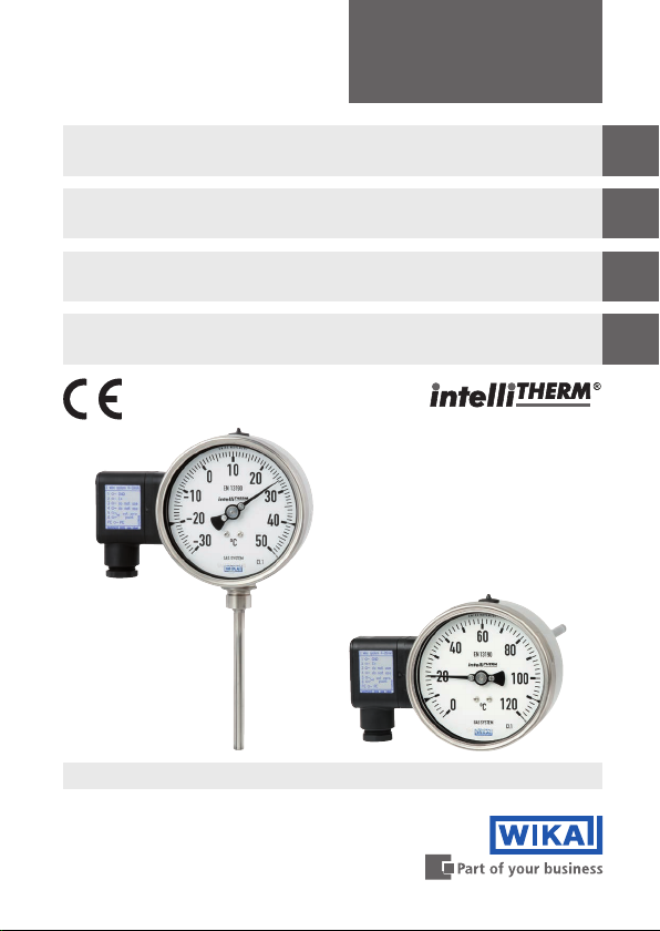
The intelliTHERM model TGT73 gas-actuated thermometer
described in these operating instructions has been designed and
manufactured using state-of-the-art technology. All components
are subject to stringent quality and environmental criteria during
production. Our management systems are certied to ISO 9001 and
ISO 14001.
■
These operating instructions contain important information on
handling the instrument.Working safely requires that all safety
instructions and work instructions are observed.
■
Observe the relevant local accident prevention regulations and
general safety regulations for the instrument's range of use.
■
The operating instructions are part of the product and must be kept
in the immediate vicinity of the instrument and readily accessible to
skilled personnel at any time.
■
Skilled personnel must have carefully read and understood the
operating instructions, prior to beginning any work.
■
The manufacturer's liability is void in the case of any damage caused
by using the product contrary to its intended use, non-compliance
with these operating instructions, assignment of insuciently
qualied skilled personnel or unauthorised modications to the
instrument.
■
The general terms and conditions contained in the sales
documentation shall apply.
■
Subject to technical modications.
■
Further information:
- Internet address: www.wika.de / www.wika.com
- Relevant data sheet: TV 17.10
1. General information

EN
14028755.03 02/2021 EN/DE/FR/ES
WIKA operating instructions model TGT73 5
Explanation of symbols
WARNING!
... indicates a potentially dangerous situation which can
result in serious injury or death if not avoided.
CAUTION!
... indicates a potentially dangerous situation which can
result in light injuries or damage to the equipment or the
environment if not avoided.
Information
… points out useful tips, recommendations and information
for ecient and trouble-free operation.
WARNING!
... indicates a potentially dangerous situation that can result
in burns, caused by hot surfaces or liquids, if not avoided.
2. Safety
WARNING!
Before installation, commissioning and operation, ensure
that the appropriate gas-actuated thermometer has been
selected in terms of measuring range, design and specic
measuring conditions.The compatibility of the wetted parts
of the process connection (thermowell, stem etc.) with the
medium must be tested.
Non-observance can result in serious injury and/or damage
to the equipment.
1. General information / 2. Safety

EN
14028755.03 02/2021 EN/DE/FR/ES
6WIKA operating instructions model TGT73
WARNING!
This is protection class 3 equipment for connection at low
voltages, which are separated from the power supply or
voltage by greater than AC 50 V or DC 120 V. Preferably,
a connection to an SELV or PELV circuit is recommended;
alternatively protective measures from HD 60346-4-41
(DIN VDE 0100-410).
Alternatively for North America:
The connection can be made in line with "Class 2 Circuits"
or "Class 2 Power Units" in accordance with CEC (Canadian
Electrical Code) or NEC (National Electrical Code).
Further important safety instructions can be found in the
individual chapters of these operating instructions.
2.1 Intended use
The gas-actuated thermometer is mainly used in the process industry to
monitor and control process temperatures.
The instrument has been designed and built solely for the intended use
described here, and may only be used accordingly.
The technical specications contained in these operating instructions
must be observed. Improper handling or operation of the instrument
outside of its technical specications requires the instrument to be
taken out of service immediately and inspected by an authorised WIKA
service engineer.
The manufacturer shall not be liable for claims of any type based on
operation contrary to the intended use.
2. Safety

EN
14028755.03 02/2021 EN/DE/FR/ES
WIKA operating instructions model TGT73 7
2.2 Personnelqualication
WARNING!
Riskofinjuryifqualicationisinsucient!
Improper handling can result in considerable injury and
damage to equipment.
■
The activities described in these operating instructions
may only be carried out by skilled personnel who have
the qualications described below.
■
Keep unqualied personnel away from hazardous areas.
Skilled personnel
Skilled personnel are understood to be personnel who, based on their
technical training, knowledge of measurement and control technology
and on their experience and knowledge of country-specic regulations,
current standards and directives, are capable of carrying out the work
described and independently recognising potential hazards.
2.3 Special hazards
WARNING!
Residual media in the dismounted gas-actuated
thermometer can result in a risk to personnel, the
environment and equipment. Take sucient precautionary
measures.
2. Safety

EN
14028755.03 02/2021 EN/DE/FR/ES
8WIKA operating instructions model TGT73
2. Safety
Scale range
Output signal
Power supply
Date of manufacture
Production number
Model
Before mounting and commissioning the instrument, ensure
you read the operating instructions!
2.4 Product label

EN
14028755.03 02/2021 EN/DE/FR/ES
WIKA operating instructions model TGT73 9
3. Specications
Gas-actuated thermometer model TGT73
Measuring element Inert gas expansion system
Nominal size 100, 160
Instrument version
■
Back mount (axial)
■
Lower mount (radial)
■
Back mount, adjustable stem and dial
■
Instruments with capillaries
Permissible ambient temperature -20 … +60 °C without/with liquid damping
Accuracy class Class 1 per EN 13190
at 23 °C ±10 °C ambient temperature
Working range
■
Continuous load (1 year)
■
Short term (max. 24 h)
Measuring range (EN 13190)
Scale range (EN 13190)
Case, ring Stainless steel
Stem, process connection Stainless steel 1.4571
Ingress protection IP65 per EN/IEC 60529
Electrical data
Power supply UB
■
4 ... 20 mA
■
0 ... 10 V
DC 12 ≤ UB ≤ 30 V
DC 15 ≤ UB ≤ 30 V
Inuenceofpowersupply ≤ 0.1 % of full scale value/10 V
Permissible residual ripple ≤ 10 % ss
Output signal, variant I 4 … 20 mA, 2-wire, passive, per NAMUR NE43
Permissible max. load RARA ≤ (UB- 12 V)/0.02 A with RA in Ω and UBin V
however max. 600 Ω
Eectofload ≤ 0.1 % of FS
Output signal, variant II 0 ... 10 V
Impedance at voltage output 0.5 Ω
Load capacity at voltage
output
2 … 100 kΩ
Sensor sampling rate 600 ms
Linearity ≤ 1.0 % of span (limit point setting)
3.Specications

EN
14028755.03 02/2021 EN/DE/FR/ES
10 WIKA operating instructions model TGT73
Electrical data
Output signal accuracy 0.2 % of FS (electronics only)
Resolution 0.15 % of FS (10 bit resolution at 360°)
Refresh rate (measuring rate) > 1/s
Input signal, angle of rotation 0 … 270 ∢ °
Long-term stability of
electronics
< 0.3 % of FS/a
Temperature error,
electronics
< 0.3 % of FS/10 K (in overall temperature
range)
Warm-up time ≤ 5 min
Permissible ambient
temperature
-20 … +60 °C without/with liquid damping
Permissible storage
temperature
-40 … +70 °C without liquid damping
-20 … +70 °C with liquid damping
Electromagnetic
compatibility (EMC)
EN 61326 emission (group 1, class B) and
interference immunity (industrial application)
Electrical connection Via angular connector, 180° rotatable,
max. 1,5 mm², cable protection, M20 x 1.5
cable gland, cable outer diameter 7 ... 13 mm,
incl. strain relief
Ingress protection IP65 to EN/IEC 60529
Protection against reverse polarity and
overvoltage
Designation of terminal
connectors dependent on
the output signal variant
Terminal
Type
1
2
3
4
5
6
Variant I
4 ... 20 mA
GND
I+
reserved
reserved
reserved
reserved
Variant II
0 ... 10 V
GND
UB+
Uout
reserved
reserved
reserved
For further specications see WIKA data sheet TV 17.10 and the order
documentation.
3.Specications

EN
14028755.03 02/2021 EN/DE/FR/ES
WIKA operating instructions model TGT73 11
4. Design and function
4.1 Description
The gas-actuated thermometer consists of a stem, capillary, Bourdon
tube and transmitter in the casing.These parts are combined to form a
single unit. The entire measuring system is lled with an inert gas under
pressure.
Any change in temperature causes a change in internal pressure in the
stem, and thus a change in the shape of the pressure element.
This motion is converted, via a mechanical movement, into a rotational
motion. A magnet on the pointer shaft rotates proportionally to the
instrument pointer as a direct linear function of the process temperature.
The downstream electronics detect the rotational motion of the magnet
in the display range.
A magnetic-eld dependent rotational sensor picks up this change on
the electronics side, contact-free, wear-free and without reaction on the
pressure element.
The rotational motion is converted into an electrical signal.The
electronics are factory set to the standard 4 ... 20 mA passive or
0 ... 10 V output signal. The span of the electrical output signal
corresponds to the measuring span on the dial.
Through these two standard electrical output signals, this instrument
can be set to almost any range in the industry.
Thermometers from the intelliTHERM range with transmitters combine
all the advantages of a local mechanical display with the industry‘s
requirements for electrical signal transmission and a modern measured
value registration.
Variations in the ambient temperature acting on the case are
compensated for by a bimetal element mounted between the movement
and the Bourdon tube.
Scale ranges with accuracy class 1 per EN 13190
between -200 ... +700 °C
4. Design and function

EN
14028755.03 02/2021 EN/DE/FR/ES
12 WIKA operating instructions model TGT73
4.2 Scope of delivery
Cross-check the scope of delivery with the delivery note.
5. Transport, packaging and storage
5.1 Transport
Check the gas-actuated thermometer for any damage that may
have been caused by transport. Obvious damage must be reported
immediately.
5.2 Packaging
Do not remove packaging until just before mounting.
Keep the packaging as it will provide optimum protection during
transport (e.g. change in installation site, sending for repair).
5.3 Storage
Permissible conditions at the place of storage:
Storage temperature: -40 … +70 °C (EN 13190) without liquid damping
-20 … +70 °C (EN 13190) with liquid damping
Avoid exposure to the following factors:
■
Direct sunlight or proximity to hot objects
■
Mechanical vibration, mechanical shock (putting it down hard)
■
Soot, vapour, dust and corrosive gases
■
Potentially explosive environments, ammable atmospheres
Store the gas-actuated thermometer in its original packaging in a
location that fulls the conditions listed above. If the original packaging
is not available, pack and store the thermometer as described below:
1. Wrap the instrument in an antistatic plastic lm.
2. Place the instrument, along with shock-absorbent material, in the
packaging.
3. If stored for a prolonged period of time (more than 30 days), place a
bag containing a desiccant inside the packaging.
4. Design ... / 5. Transport, packaging and storage

EN
14028755.03 02/2021 EN/DE/FR/ES
WIKA operating instructions model TGT73 13
WARNING!
Before storing the instrument (following operation), remove
any residual media.This is of particular importance if
the medium is hazardous to health, e.g. caustic, toxic,
carcinogenic, radioactive, etc.
The use of liquid damping is always recommended for
temperatures near the dew point (±1 °C around 0 °C).
6. Commissioning, operation
When screwing the instruments in, the force required to do this must not
be applied through the casing, but only through the spanner ats
provided for this purpose, and using a suitable tool.
■
If possible, the entire length of the stem should be exposed to the
temperature being measured. However, at least the length of the
active part that corresponds to the length of the gas expansion
vessel (active length).
■
In pipelines or other measuring points, the temperature probe must
be angled as far towards the ow as possible.
Installation with
open-ended spanner
5. Transport ... / 6. Commissioning, operation

EN
14028755.03 02/2021 EN/DE/FR/ES
14 WIKA operating instructions model TGT73
6. Commissioning, operation
■
Errors in thermal conduction occur if the area where the temperature
is to be measured is so small, that the mass of the temperature probe
acts as thermal capacity. Errors in thermal conduction may also
occur if the immersion depth is insucient, if the mounting ttings
are connected to a good thermal conductor (metal plate or similar)
and there is a considerable dierence in temperature between the
measuring and mounting element temperatures.
■
The dial casing must be mounted free from vibration. If necessary,
it is possible to isolate the instrument from the mounting point by
installing a exible connection line between the measuring point and
the thermometer and mounting the instrument on a suitable bracket.
If this is not possible, the following limit values must not be exceeded:
Frequency range < 150 Hz
Acceleration < 0.5 g (5 m/s2)
The liquid lling must be checked on a regular basis.
The liquid level must not drop below 75 % of the gauge diameter.
Heavy shocks, oscillations and vibrations lead to imprecise values,
increased wear in the movement, and fractures on welded or soldered
joints.

EN
14028755.03 02/2021 EN/DE/FR/ES
WIKA operating instructions model TGT73 15
6. Commissioning, operation
When mounting a gas-actuated thermometer that can be rotated and
swivelled, the specic instructions must be followed. In order to set the
indicator to the desired position, the following steps must be taken:
1.The lock nut or union nut must be loosened at the process
connection.
2.The hexagon bolts and slotted screws at the swivel joint must be
loosened.
3. Position the indicator as required, tighten the hexagon bolts and
slotted screws, and nally tighten the lock nut or union nut rmly.
loosening
Make sure the screws on the
opposite side are loosened
as well!

EN
14028755.03 02/2021 EN/DE/FR/ES
16 WIKA operating instructions model TGT73
6. Commissioning, operation
6.1 Use of thermowells
CAUTION!
Damage due to incorrect handling
When using thermowells, please ensure that the stem does
not touch the bottom of the thermowell since, due to the
dierent expansion coecients of the materials, the stem
may become buckled at the bottom of the thermowell.
▶Use the correct insertion length (for the formula for the
calculation of the insertion length, l1, see the respective
thermowell data sheet).
6.2 Thermal contact medium
When using thermowells, they must be lled with a thermal contact
medium in order to reduce the heat transfer resistance between the
outer wall of the probe and the inner wall of the thermowell.The working
temperature of the thermal compound is -40 ... +200 °C.
Thermowell
Stem
required safety
clearance

EN
14028755.03 02/2021 EN/DE/FR/ES
WIKA operating instructions model TGT73 17
WARNING!
Physical injuries and damage to equipment due to oil
spraying out
When pouring a thermal contact medium into a hot
thermowell, there is a danger of physical injuries and damage
to equipment due to oil spraying out.
▶Do not ll hot thermowells
7. Mounting instructions for contact bulb
The contact bulb has been designed for mounting on pipes or tanks.
When mounting this thermometer version, it must be ensured that the
contact bulb is in contact with the measuring point over its complete
length.The basic requirements to ensure a perfect measurement result
is to retain good thermal contact between the skin mounted contact bulb
and the outside wall of the pipe or tank with minimal heat loss to
ambient from the skin mounted contact bulb and measuring point.
Capillary
Bend protector
3107876.01
6. Commissioning, operation / 7. Mounting ...

EN
14028755.03 02/2021 EN/DE/FR/ES
18 WIKA operating instructions model TGT73
7.1 Mounting to pipes
The geometry of the contact bulb
has been designed for pipes with
external diameters between 20
and 160 mm.The skin mounted
contact bulb should have direct
metallic contact with the measuring
point and have rm contact with
the surface of the pipe.Where
temperatures under 200 °C are to
be expected, a heat conducting
paste can be used to optimise the heat transmission between skin
mounted contact bulb and pipe. Lagging must be applied where the skin
mounted contact bulb has been mounted, in order to avoid error due to
heat loss. This lagging must have sucient temperature resistance and
is not provided with the instrument.
7.2 Mounting to vessels
The geometry of the contact bulb
has been designed for vessels with
an external radius up to 80 mm.
If the mounting point of the skin
mounting contact bulb on the tank
has an external radius greater than
80 mm, we recommend the use of
an intermediate piece designed
for the respective vessel diameter,
made of a material with good thermal conductivity. The contact bulb
should be fastened to the vessel by means of an angle bracket with
clamping screws, or any similar method.The skin mounted contact bulb
should have direct metallic contact with the measuring point and have
rm contact with the surface of the vessel.
A heat conductive paste can be used to optimise the heat transmission
between skin mounted contact bulb and the vessel, if temperatures
under 200 °C are to be expected. Lagging must be applied where
the skin mounted contact bulb has been mounted, in order to avoid
error due to heat loss. This lagging must have sucient temperature
resistance and is not provided with the instrument.
3107922.01
Tube clip mounting
Lagging
3107930.01
Angle bracket mounting
Lagging
7. Mounting instructions for contact bulb

EN
14028755.03 02/2021 EN/DE/FR/ES
WIKA operating instructions model TGT73 19
8. Electrical connection
The electrical connection of the transmitter is made through an angular
connector. The exact pin assignments can be found in the following
drawings. In addition, the pin assignment, output signal and the required
power supply are stated on the product label.
Explanation of the terminal assignments used:
UB+ Positive terminal of the power supply
0 V Negative terminal of the power supply
Sig+ Positive terminal of the output signal
Sig- Negative terminal of the output signal
The instruments must be connected to the equipotential bonding of the
plant.
Designation of terminal connectors
Terminals 1 and 2 are the connection terminals for the signal output
and the power supply, respectively. The terminal labelled PE (protective
earth) is internally connected to the casing. The connections 3 to 6 or
4 to 6 in the 3-wire variant, should be left free and must not be used as
points (see also chapter 3 "Specications").
WARNING!
The gas-actuated thermometer with integrated rotary
encoder must be grounded through the thermometer
housing and through the ground terminal in the angular
connector.

EN
14028755.03 02/2021 EN/DE/FR/ES
20 WIKA operating instructions model TGT73
8. Electrical connection / 9. Maintenance and ...
2-wire system
(e.g. 4 ... 20 mA)
3-wire system
(e.g. 0 ... 10 V)
Earth, connected
to case
Terminals 3, 4, 5 and 6:
only for internal use
UB+/Sig+
+0V/Sig-
Evaluation
(display)
Power supply
Terminal box Earth, connected
to case
Iout/Uout
Terminals 4, 5 and 6:
only for internal use
UB+/Sig+
+0V/Sig-
Evaluation
(display)
Power supply
As a power supply, an unstabilised DC power supply is sucient, with a
max. ripple of 10 % ss in the range of the specied power supply limits.
It is important to ensure that the applied power supply is at least greater
than the maximum required voltage drop from the external display and
evaluation units; i.e. the voltage at the transmitter must not fall below
12 V.
9. Maintenance and cleaning
9.1 Maintenance
Gas-actuated thermometers with transmitters are maintenance-free!
The indicator should be checked once or twice every year.To do this the
instrument must be disconnected from the process and checked using
a temperature calibrator.
Repairs must only be carried out by the manufacturer.
Table of contents
Languages:
Other WIKA Thermometer manuals