English
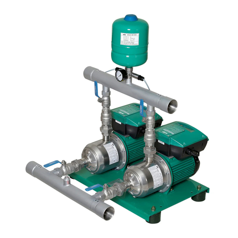
Installation and operating instructions Wilo domestic water systems HiMulti3..H.. /HMHI/HWJ 25
In case of fixed or stationary installation, the domes-
tic water system shall be attached to the floor on-
site. The installation surface must be horizontal and
flat. Space shall be allowed for maintenance work.
NOTE:
Never install the domestic water system on an
uneven bearing surface!
To avoid structure-borne noise transmission, the
domestic water system must be connected to the
suction and pressure pipes via flexible hose
adapters. Threaded pipe unions which can be
opened must be used for this.
In case of additional on-site attachment to the
ground, make sure that suitable measures are pro-
vided in order to avoid structure-borne noise
transmission (e.g. by a cork pad, vibration absorb-
ers or the like). To fasten the domestic water sys-
tem to the floor, appropriate holes are provided
(for 4 Ø6 mm (50 L) or Ø8 mm screws (20 L and
100 L) – not included in the scope of delivery) on
the installation feet (see Fig. 1 and 2 and the table
of connection and technical data in Section 5.2).
7.1.1 Domestic water system (Fig. 3a and 3b)
A non-self-priming pump is supplied with water via
the inlet connection (see Fig. 3a and 3b). The water
supply can come from a higher tank (Fig. 3a) or a
water supply network (Fig. 3b).
CAUTION!
In order to guarantee correct operation, the
pumps require a water supply of at least
300 mm, i.e. the first extraction point in the
consumer line must be installed at least 300 mm
above the pump.
Suitable stop valves shall be installed in the inlet
pipe and the consumer line (Fig. 3a and 3b,
item 11/12). The inlet pipe shall be provided with
a non-return valve (Fig. 3b, item 13) or a spring-
mounted foot valve (Fig. 3a, item 10). The diame-
ter of the inlet pipe must not be less than the
diameter of the pump's suction connection.
To avoid stresses being communicated by the
weight of the piping, the piping must be secured
to the structure using suitable attachment devices
(Fig. 3a and 3b, item 14).
7.1.2 Domestic water system in suction mode
(Fig. 3c)
With a self-priming pump or a non-self-priming
pump operating in suction mode from tanks at a
lower level, it is necessary to install a separate,
vacuum and pressure-resistant inlet pipe with
foot valve (Fig. 3c). This must be installed contin-
uously rising from the tank to the pump connec-
tion on the suction side. The foot valve shall be
positioned so as to achieve a distance of 100 mm
from the base of the tank and a minimum water
coverage of 200 mm at the lowest possible water
level.
Use of a suction hose set (comprising a suction
hose and foot valve) is always recommended.
A floating extractor should be installed in order to
prevent coarse contaminants being sucked in
from the base area of the container.
Suitable stop valves shall be installed in the con-
sumer line (Fig. 3c, item 12).
All connection lines shall be installed on the system
without tension, using detachable connections.
The weight of the connection lines must be secured
to the building structure using suitable attachment
devices (Fig. 3c, item 14).
7.2 Electrical connection
WARNING! Risk of electric shock!
• Dangers from electricity must be ruled out.
• Electrical work may only be carried out by a
qualified electrician authorised by the local
electricity supply company and in accordance
with the applicable local regulations (e.g. VDE
regulations).
• Before any electric connection must be discon-
nected from the power supply (switched off)
and protected against unauthorised reactiva-
tion.
• In order to ensure safe installation and opera-
tion, the unit must be earthed correctly with the
earth terminals of the power supply.
CAUTION!
Defects in the electrical connection damage the
motor.
The power cable should never be allowed to
come into contact with either the pipe or the
pump. Furthermore, it must be completely
shielded against moisture.
We recommend connecting the domestic water
system via a residual-current device (Fl switch).
The appropriate regulations acc. to VDE 0100 Part
702 shall be complies with for use in swimming
pools and garden ponds.
Mains connection:
• EM version: Connection via connection cable with
plug (Fig. 1 to 3, item 6, installed ex-works in
accordance with the connection diagram Fig. 6a to
6d, depending on the pump used)
• DM version: Connection by on-site connection
cable (for diagram, see Fig. 7b)
• The cover of the pressure switch must be
removed for this purpose (Fig. 7).
• A four-core cable must be routed to the “LINE”
terminals (phases) and the earthing connection
(green/yellow).
• The domestic water system must only be oper-
ated with an electrical connection cable (includ-
ing extension cable) which has at least a rubber
sheath of type H07 RNF acc. to DIN 57282 or
DIN 57245.