2
Table of contents / Inhaltsverzeichnis / Indholdsfortegnelse
Table of contents / Inhaltsverzeichnis / Indholdsfortegnelse .......................................................................................2
1UK –Installation instruction....................................................................................................................................2
1.1 Connection to WSC 310 / 320 STANDARD and PLUS..........................................................................................2
1.2 Connection to WSC 5xx.........................................................................................................................................4
1.3 Fault indication.......................................................................................................................................................4
2DE –Anleitung..........................................................................................................................................................5
2.1 Anschluss an WSC 310 / 320 STANDARD und PLUS...........................................................................................5
2.2 Anschluss an WSC 5xx..........................................................................................................................................6
2.3 Fehleranzeichen.....................................................................................................................................................7
3DK –Installationsvejledning....................................................................................................................................7
3.1 Tilslutning til WSC 310 / 320 STANDARD og PLUS..............................................................................................7
3.2 Tilslutning til WSC 5xx ...........................................................................................................................................9
3.3 Fejlindikering..........................................................................................................................................................9
1 UK –Installation instruction
Break glass unit Connection possibilities
WSK 501 & WSK 502 Smoke detector and comfort keypads can be connected to the break glass unit.
WSK 503 & WSK 504 Smoke detector and comfort keypads cannot be connected to the break glass unit.
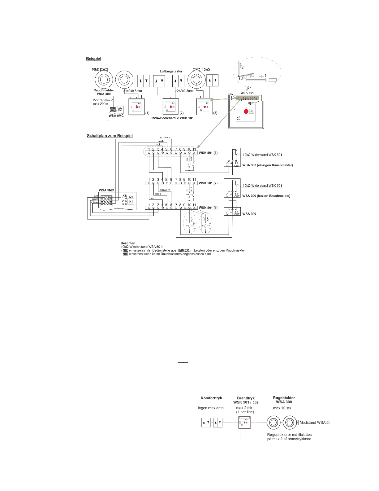
1.1 Connection to WSC 310 / 320 STANDARD and PLUS
If keypad and smoke detector are to be connected to the
break glass unit, WSK 501 or WSK 502 are to be used. Max
one of these break glass unit on each motor line, the
remaining units (up to four) must be of type WSC 503 or
WSC 504
Up to 10 smoke detectors can be connected to each WSK
501 / 502. There is no limit on the number of ventilation
keypads connected to the WSK 501 / 502.