Wine Corner WINEMASTER WINE ARM 15 Operation manual

INSTALLATION & USER GUIDE
D E F Y I N G
C O N V E N T I O N
WINE ARM 15
AND
WINEARM 15 DUAL AIR KIT

CONTENTS
1.
CABINET LAYOUT 5
1.1.
Evacuatio 5
1.2.
Cabi et i sulatio 5
1.2.1.
Walls, ceili g a d floor i sulatio 6
1.2.2.
Doors 6
2.
INSTALLATION OF THE WINEMASTER
®
CONDITIONING UNIT 7
2.1.
Cutti g the ceili g 7
2.2.
I stallatio of the co ditio i g u it 8
2.2.1.
I sertio of the applia ce from the i side of the cabi et 8
2.2.2.
I sertio of the applia ce from above 8
2.2.3.
I stallatio of the water drai -off 9
2.2.4.
Duct ve tilatio 9
2.2.5.
I stallatio of the thermostat 10
2.2.6.
I stallatio of the hood 10
3.
SWITCHING ON THE WINEMASTER
®
CONDITIONING UNIT 11
3.1.
Co ecti g the co ditio i g u it 11
3.2.
Switchi g o 11
3.2.1.
Setti g the temperature
11
3.2.2.
Sta dby mode
12
3.2.3.
Automatic defrost
12
4.
SERVICING & MAINTAINING THE WINEMASTER
®
CONDITIONING UNIT 13
4.1.
Mai tai i g the dust filter 13
4.2.
Co de sate evacuatio pipe 13
Clea Pipe 14
Drai Excess Water i Evaporatio Tray 15
5.
WARRANTY 16
5.1.
Statutory warra ty 16
5.2.
2-year co tractual warra ty 16
5.3.
Warra ty applicatio co ditio s 16
5.4.
Warra ty exclusio s a d limitatio s 16
Page 2

INTRODUCTION
Tha k you for purchasi g a WINEMASTER
®
co ditio i g u it.
We have do e everythi g to offer you a exclusive a d very high-quality product. Mi dful of this
philosophy a d produced from the work of a whole team i creasi gly motivated by customer
satisfactio , we hope that your WINEMASTER
®
co ditio i g u it provides you with the optimal
co servatio a d agei g co ditio s for your wi es.
This I stallatio a d User Guide is here to help you optimise the daily use of your co ditio i g u it.
You will fi d tech ical i formatio
a d practical advice e suri g you progress smoothly through the
esse tial i stallatio a d usage phases.
Page 3

CHARACTERISTICS
WINEARM15
Weight of applia ce 31 kg
Dime sio s of applia ce L908xD439xH316
Cut-out dime sio s 890 x 428
Temperature setti g
preset to 12°C, (adjustable betwee 4 a d 15°C)
*
M x. outside (air i let) temperature
30°C **
Cooli g power
500 W at 15°C
**
Electrical power supply 235V-50 Hz + 3 metre cable
Absorbed electrical power 400 W
The circuit breaker must be 16 Amps
*
With i sulatio appropriate to the ambie t temperature a d volume of the cellar.
**
Si ce the power dimi ishes as a fu ctio of the outside temperature, the applia ce might lose its capacity to
mai tai 12°C if the outside (air i let) temperature ears 27°C as a co sta t temperature.
If the thermal safety fu ctio is triggered too freque tly, this may damage the compressor prematurely.
In ll c ses, ensure the temper ture of the ev cu tion room (where the used ir from the unit is vented to), is lower th n
30°C const nt for no more th n few weeks in the ye r (Summer se son).
TECHNICAL & DIMENSIONAL DRAWING
Page 4

1.
CABINET LAYOUT
1.1.
EVACUATION (Air Outlet)
The hot air produced by the co ditio i g u it must be correctly evacuated so that it is ot reused for the cooli g
fu ctio (air i let).
Maximum a d o -perma e t i let temperature 30°C
Optimal air i let temperature 20°C
VENTILATED COOLING OR “NO FROST”
The be efits of ve tilated cooli g:
•
No frost formatio other tha o the evaporator.
•
Automatic defrost produci g maximum refrigeratio efficie cy.
•
Cold circulatio improved by co ti uous air moveme t, o air stratificatio .
•
Air circulatio allows for rapid retur to the preset temperature.
1.2.
CABINET INSULATION
This is vit l to e sure the efficie t operatio of the WINEMASTER
®
. Adequate i sulatio will help to e sure optimum
temper ture nd humidity st bility. The table below (Choice of i sulatio ) assists with determi i g the type a d
thick ess of the ecessary i sulatio as a fu ctio of the outside volume of the cellar a d the WINEMASTER
®
model,
a d based o a i terior temperature of 12°C.
INSULATION CONTINUITY
The i sulatio eleme ts should preferably be assembled:
•
By “to gue a d groove” pa els, or
•
By bo di g the pa els together
OBJECTIVE:
To prevent the unw nted entry of he t nd moisture which will d m ge the irtight se l
To prevent moisture migr tion in the cell r, v pour b rrier should be integr ted within the f bric of the
w lls.
Page 5

1.
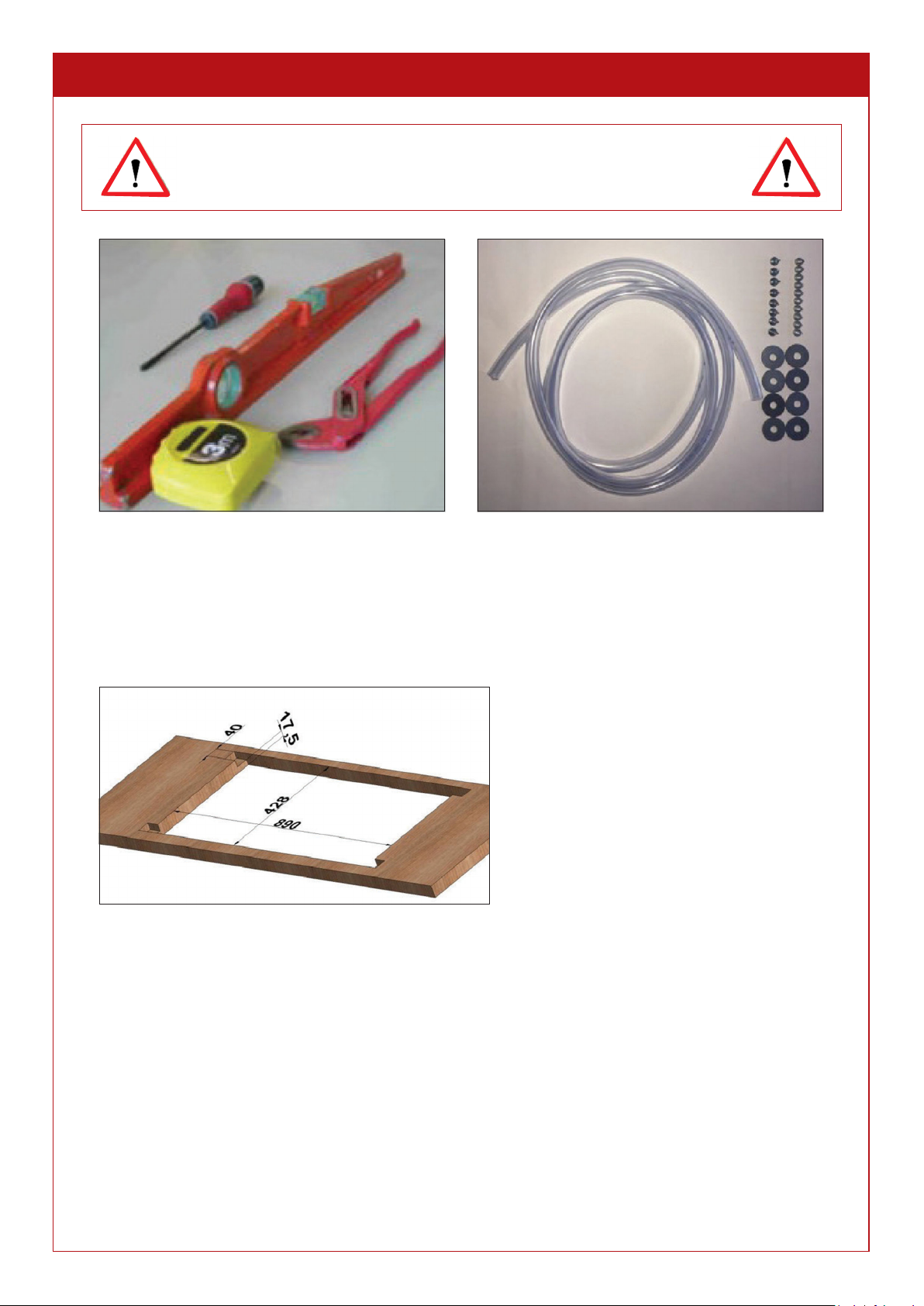
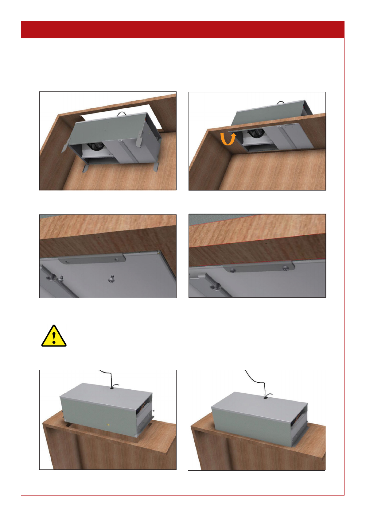
CABINET LAYOUT Cont.
C binet volume (m³)
Polystyrene fo m
= 0.044 W/m°C
(mm)
Extruded polystyrene
= 0.030 W/m°C
(mm)
Polyureth ne fo m
= 0.025 W/m°C
(mm)
2
25 20 20
3
30 25 20
4
40 30 25
5
45 30 25
6
50 35 30
8
60 45 40
10 80 55 45
12 90 65 55
15 110 80 70
1.2.1
WALLS, CEILING AND FLOOR INSULATION
Choice of insul tion p nels
The ma ufacturers recomme d the followi g i sulatio pa els:
•
Si gle layer i sulatio pa els
•
“Complex” i sulatio : i sulatio is covered with a claddi g material (plaster, mi eral, etc.),
•
Sa dwich: i sulatio is covered o each side with a woode pa el or plaster board.
Important:
Coveri gs protect the i sulatio from impact a d guara tees its lo gevity. Avoid usi g
mi eral- fibre i sulatio pa els (glass wool, rock wool, etc.) as they ca absorb moisture a d lose their
i sulatio qualities.
Floor insul tion
The cellar floor must be able to support the racks a d the wi e stored. I sulatio must therefore be chose with a
sufficie t compressive resista ce.
Reduce the risk of damage from pu ctures (i.e. from wi e racks or shelvi g legs) by usi g the followi g:
•
“Complex” i sulatio pa els, coveri g their top side with a sufficie tly resista t pa el.
•
Coveri g the i sulatio with a chipboard pa el (thick ess arou d 15 mm), or a y other appropriate coveri g
(e.g.
screed a d slab).
1.2.2
DOORS
These form part of the i sulatio co ti uity. There are two possible solutio s:
•
Glazed doors: double-glazi g or eve triple-glazi g must be used with a good UG coefficie t (max. 1.2 W/…….)
•
If solid doors are used, they should be i sulated i the same way as the other walls.
Page 6
DID YOU KNOW?
Some i sulati g materials are damaged by rode ts (mice, rats, etc.). You should therefore check that the cellar
walls have o gaps or cracks through which rode ts ca reach the i sulatio . If ecessary, cover the
i sulatio o the i side of the cellar with a protective li er.
Polyuretha e as a i sulati g material, due to its chemical compositio , will ot be damaged by rode ts.

2.
INSTALLATION OF THE WINEMASTER
®
CONDITIONING UNIT
Tools required (not supplied) Items included in box
2.1
CUTTING THE CEILING
Cut a space i the ceili g to house the co ditio i g u it.
Cut the ceiling and adjust the slots for the legs if these are used
Page 7
THE APPLIANCE MUST INSTALLED IN COMPLIANCE
WITH NATIONAL ELECTRICAL INSTALLATION RULES
1.

2. INSTALLATION OF THE WINEMASTER
®
CONDITIONING UNIT Cont.
2.2
INSTALLATION OF THE CONDITIONING UNIT
2.2.1
INSERTION OF THE APPLIANCE FROM THE INSIDE OF THE CABINET
The co ditio i g u it ca be positio ed i the ceili g from the i side of the cabi et a d faste ed i place with
the 4 swivel legs fitted to the co ditio i g u it o each cor er.
Engage the conditioning unit in the cut-out space Turn the 4 legs
Scre in place using the 4 x 6 scre s supplied
2.2.2
INSERTION OF THE APPLIANCE FROM ABOVE
Before attempti g to positio the Wi earm15 from u der eath the ceili g, e sure there
is e ough space i the ceili g void to accommodate moveme t of the u it while lifti g it
i to place.
Whe i stalli g from above, remove the 4 swivel legs a d use the brackets supplied if eeded.
Insert the unit into the cut-out space from above Fix the brackets ith the scre s supplied
Page 8
2.
3.
4.
5.
2.
3.

2. INSTALLATION OF THE WINEMASTER
®
CONDITIONING UNIT Cont.
2.2.3
INSTALLATION OF THE WATER DRAIN-OFF
The co ditio i g u it has a co de sate evaporatio system. However, there is a overflow to evacuate excess water
caused by the i adequate seali g of the cabi et or the doors remai i g ope for too lo g. You ca drai off the water
usi g a PVC pipe to cha el the water i to a co tai er.
2.2.4 INSTALLATION OF THE THERMOSTAT
The thermostat can be installed
in the cabinet, on the side of the
cabinet or outside the cabinet.
The temperature probe/sensor
(S) should be positioned
to ards the return air zone (R).
We recommend that the end of
the sensor does not touch the
partition and is placed in the air
flo .
Page 9
IF THE POWER CABLE IS DAMAGED, IT MUST BE REPLACED BY THE
MANUFACTURER, ITS AFTER-SALES SERVICE OR PERSONS WITH A
SIMILAR QUALIFICATION TO AVOID RISK OF HARM.

2.
INSTALLATION OF THE WINEMASTER
®
CONDITIONING UNIT Cont.
2.2.5 INSTALLATION OF THE HOOD
The hood is inserted on the left at the point of the slots and
then scre ed in. The filter cover is magnetic.
Page 10
IMPORTANT: AFTER TRANSPORT OR HANDLING, WAIT 24 HOURS
BEFORE SWITCHING ON THE CONDITIONING UNIT.

3.
SWITCHING ON THE WINEMASTER
®
CONDITIONING UNIT
The thermostat displays the air temperature i side the air-co ditio ed room, withi a ra ge of 2°C. The thermostat
is factory-set to the setpoi t temperature of 12°C. Whe the co ditio i g u it is switched o , you should check a d
modify this temperature if ecessary, followi g the releva t procedure (§4.2.1).
3.1.
CONNECTING THE CONDITIONING UNIT
When you switch on the conditioning unit, the temper ture of the room is displ yed:
-
If the temperature is higher tha the thermostat setpoi t (12oc), the co ditio i g u it will start after a 2-
mi ute time i terval.
-
If the temperature is less tha the thermostat setpoi t (12oC), the compressor will ot start, a d the i terior
u it fa will begi to tur .
3.2.
SWITCHING ON
3.2.1.
Setti g the temperature
The setpoi t temperature is set o the thermostat:
•
Press the butto for o e seco d u til the setpoi t temperature flashes.
1
•
Use the butto to i crease the setpoi t temperature.
2
•
Use the butto to reduce the setpoi t temperature.
3
•
Whe the temperature setti g is correct, press the butto to co firm
Me nings of the m in symbols on the digit l displ y:
Red light illumi ated o display = cold mode e gaged (compressor is ru i g)
Red light illumi ated o display = quick ve tilatio i cold mode
Red light illumi ated a d displayed “dF” = automatic defrost i progress
Red light illumi ated o display = heat mode e gaged (resista ce)
Red light illumi ated o display = alarm (a flashi g message specifies the ature)
“IA” display = exter al alarm or door ope (depe di g o versio )
“dEF” display = Ma ual defrost i progress (see 1.2.4)
The unit will be delivered with a setpoint of 12
o
C. Unless directed by a Winemaster En ineer,
there will be no need to chan e the setpoint, whatever the circumstances.
Page 11
IMPORTANT: AFTER TRANSPORT OR HANDLING, WAIT 24 HOURS
BEFORE SWITCHING ON THE CONDITIONING UNIT.

3.
SWITCHING ON THE WINEMASTER
®
CONDITIONING UNIT Cont.
3.2.2. Sta dby Mode
•
Placi g the co ditio i g u it i sta dby mode: keep butto 1 pressed for 3
1 seco ds. The compressor stops a d the fa tur s at low speed.
•
The thermostat display alter ates betwee “
OFF
” a d the cellar temperature.
•
To exit sta dby mode, press butto 1 agai for 3 seco ds.
•
The thermostat displays “ON” for 1 seco d.
3.2.3.
Automatic Defrost
The thermostat is programmed to ru a automatic defrost at regular i tervals. This i volves the shutdow of the
compressor, while the i terior u it fa will co ti ue to tur at low-speed. A y co de sates produced by the defrost
will be evacuated to the evaporatio pa placed u der eath the compressor i side the Wi emaster
®
.
3.2.4.
Ma ual Defrost
•
Ma ual defrost is ot ecessary, but ca however be activated by pressi g
butto 3 for 3 seco ds. The compressor shuts dow .
•
The thermostat display alter ates betwee “
dEF
” a d the cellar temperature.
To
exit ma ual defrost mode, press butto 3 agai for 3 seco ds.
•
The thermostat displays
“
ON
”
for 1 seco d.
The unit will be delivered with a setpoint of 12
o
C. There are very few circumstances where
the controls need to be used or the setpoint needs to be chan ed.
If in doubt, leave the controls alone and contact Wine Corner for advice.
Page 12

4.
SERVICE & MAINTENANCE
4.1.
DUST FILTER – REGULAR CLEANING AND FITTING NEW
The u it is equipped with a dust filter, which protects the co ditio i g u it with a clea air i take. It is crucial that the
dust filter is clea ed every 3 mo ths a d re ewed at least o ce a year. The filter is accessed from the bottom of the
co ditio i g u it as show i the diagram below.
•
Remove the magnetic cover
•
Use a scre driver to remove the 2 scre s securing
the shutter
•
Remove the filter
•
Clean and replace
OR
•
Fit a ne filter, at least every 12 months.
4.2.
CONDENSATE EVACUATION PIPE – ANNUAL MAINTENANCE
Check the pipe is completely clear whe checki g the filter. Clea the pipe at least o ce a year.
•
Remove the outer hood (see 2.2.6)
•
Grip the flexi-pipe firmly, and pull to remove
•
Remove any deposits in the pipe
•
Clean the pipe
•
Firmly, push the flexi-pipe back into position
•
Reassemble the hood
Page 13
DIRTY/DUSTY FILTER = DAMAGED CONDITIONING UNIT
USE WINEMASTER
®
FILTERS ONLY

13
SERVICING & MAINTAINANCE
Page 14
4.
SERVICE & MAINTENANCE
4.
SERVICE & MAINTENANCE

Page 15
4.
SERVICE & MAINTENANCE

5.
WARRANTY
5.1.
2-YEAR CONTRACTUAL WARRANTY
The co ditio i g u it has a 2-year warra ty agai st all ma ufacturi g defects.
Duri g the co tractual warra ty period, Wi e Cor er Ltd will replace a y part recog ised as faulty.
Depe di g o the case, the Wi e Cor er after-sales service may request the retur of the faulty part. A y
ew parts fitted will ot serve to exte d the warra ty period, either will parts warra ty apply.
Collectio a d/or delivery costs of faulty or ew parts must be paid for by the customer.
Interventions nd returns should t ke pl ce only fter written greement with Wine Corner Ltd.
5.2.
WARRANTY APPLICATION CONDITIONS
The co tractual warra ty applies to all applia ces i stalled a d used i accorda ce with the “I stallatio
a d User Guide”. Its applicatio is depe de t upo the prese tatio of the purchase i voice.
5.3.
WARRANTY EXCLUSIONS AND LIMITATIONS
The warra ty is excluded i the followi g cases:
•
The i sulatio of the climate-co trolled room a d the i stallatio fail to comply with the i structio s of this
Guide.
•
The faults are due to eglige ce, poor repair, i correct or improper use of the WINEMASTER®
co ditio i g u it (particularly the cloggi g of the filters).
•
The applia ce has bee modified
Wi e Cor er Ltd will u der o circumsta ce be liable for the direct or i direct co seque ces of the
o -operatio of the co ditio i g u it.
The w rr nty is limited exclusively to the product supplied by Wine Corner Ltd.
Page 16
The Europea Commu ity, placi g great importa ce o the e viro me t a d the
treatme t of waste, impleme ted Directive 2002/96/EC relati g to Electrical a d
Electro ic Waste (WEEE).
I accorda ce with this Directive, the prese ce of the logo o the left is
compulsory.
This logo mea s that the product
must never be disposed of in household w ste
.
It must be take to a suitable collectio poi t for the processi g, recovery a d
recycli g of electrical a d electro ic waste.
By doi g so, you are acti g for the e viro me t a d co tributi g to the
protectio of atural resources a d huma health.
5. WARRANTY TERMS AND CONDITIONS

(Deliber tely left bl nk)
Page 17

Tel: 00 44 (0) 1302 744916
or 03333 702589
WineCornerUK
@winecorner1
linkedin.com/company/wine-corner-l d
DEFYING
C O N V E N T I O N
Other manuals for WINEMASTER WINE ARM 15
1
This manual suits for next models
1
Table of contents
Other Wine Corner Wine Cooler manuals

Wine Corner
Wine Corner JG32 User manual

Wine Corner
Wine Corner Wine PC15 User manual

Wine Corner
Wine Corner Wine C25 User manual

Wine Corner
Wine Corner CI140CF User manual

Wine Corner
Wine Corner WINE IN50+ User manual

Wine Corner
Wine Corner Winemaster C50 IN User manual

Wine Corner
Wine Corner WINE SP100 User manual

Wine Corner
Wine Corner SP40DUPRO Operation manual