manuals.online logo
Brands
  1. Home
  2. •
  3. Brands
  4. •
  5. Winegard
  6. •
  7. Antenna
  8. •
  9. Winegard HD7698 User manual

Winegard HD7698 User manual

1450292
Rev7 3-21
VHF/UHF MODELS
HD7698 &HD8200
High Definition VHF/UHF Antennas
INSTRUCTION MANUAL
Register your product at winegard.com/myantenna
For help, email [email protected]
HD7698
HD8200
WARNING:Installation of the antennas near power lines is dangerous!
For your safety, follow the installation instructions.
POINT THIS END
TOWARD STATIONS
POINT THIS END
TOWARD STATIONS
NOTE: Unfolding elements procedure is the same for both
HD7698 &HD8200 antennas.
PARTS LIST
ASSEMBLY
STEP 1 - Contents of Package
A. Remove all parts from the box and compare to parts list
to ensure nothing is missing and to become familiar with
the part names. See figure1.
STEP 2 - Front Section
A. Stand front section up vertically and unfold all elements
(in any order) until they snap into place.
B. Remove bolt, hex nut, and director element from the
front section boom. See figure 2.
C. Unfold the UHF directors. See figure 2.
D. Set front section aside being careful not to bend
the elements (laying it flat on the ground is the
best position).
Front Assembly
Rear Assembly
Mast Clamp
Mast Clamp
Boom Brace
Corner Reflector Assembly (2)
Flat Head Screwdriver
Phillips Screwdriver
Crescent Wrench or Pliers
Cartridge
Housing
Boot
TOOLS REQUIRED
(not included)
FIGURE 1
FIGURE 2 -Front Assembly FIGURE 3 - Rear Assembly
UHF Director,
(Unfolded)
UHF Directors UHF Directors
Director Element
Cartridge Housing
8 Up
6 Up
4 Up, Over &Down
2 Up, Over &Down
7 Down, Over & Up
5 Down
3 Down
1 Down
STEP 3 - Rear Section
A. Stand rear section up vertically with cartridge housing up
and facing away from you.
B. Alternately unfold elements per figure 3 in direction
of arrows until they lock into place in the black plastic
blocks.
C. Spin the rear section around so the cartridge housing is
now facing you. Unfold the remaining elements in the
same order. See figure 3 for completely unfolded rear
section.
WARNING: Be sure the phasing lines DO NOT touch the
metal bracket or the antenna boom. See FIGURE 4.
NOTE: The HD8200 antenna tuning stubs do not need
to touch the boom.
STEP 4 - Attaching Front Section to Rear Section
A. Slide the front boom into the rear boom making sure to
feed the UHF phasing lines into the holes near the top
of the cartridge housing, and into the slotted pegs inside
the housing. See figure 4. When finished, the phasing
lines will be resting in the slots of the pegs, but will not
extend out the back side of the cartridge housing.
B. Reinstall the director element, bolt and nut. See
figure 2.
STEP 5 - Cartridge Housing
A. Attach the cartridge housing cover so all 4 snaps are
locked in place. Direction of the housing does not matter.
See figure 5.
STEP 6 - Corner Reflector Assemblies
A. Unfold the elements on the corner reflector booms.
Element clip tips should point away from the open end of
each boom. See figure 6.
B. Attach the corner reflector booms using the supplied
nuts and bolts. See figure 6.
STEP 7 - Boom Brace
A. Install the boom brace by first removing the bolts and
hex nuts.
B. With the cartridge housing facing down, install the boom
brace to the top corner reflector boom first, making sure
the mast clamps are on the same side. See figure 7.
Only finger tighten the bolt and hex nut.
C. Swing the other end of the boom brace down onto the
rear section and insert the bolt and hex nut.
D. Tighten both bolts and nuts (on each end of the boom
brace) securely.
FIGURE 4 - Front Section to Rear Section
FIGURE 5 - Attach Cartridge Housing
FIGURE 6 - Corner Reflector Assemblies
FIGURE 7 - Boom Brace Installed
Cartridge Housing
UHF Phasing Lines
Cartridge Housing
V-shaped
tuning stub
Element Clip Tips
Pointing away from
open end of boom
Attach the corner
reflector booms
Install this
end first
Install this
end last
Mast
Clamps
Cartridge Housing,
(Facing Down)
Be sure the phasing
lines DO NOT touch
the metal bracket or
the antenna boom.
90 DAY LIMITED WARRANTY
Winegard Company warrants this Winegard product against any defects in materials or workmanship within 90 (ninety) days from date of purchase. No warranty claim will be honored unless at the
time the claim is made, you present proof of purchase to an authorized Winegard dealer (if unknown, please contact Winegard Company, 3000 Kirkwood Street, Burlington, IA 52601-2000, Telephone
800-288-8094).
Winegard Company (at its option) will either repair or replace the defective product at no charge to you. This warranty covers parts, but does not cover any costs incurred in removal, shipping or
reinstallation of the product. This limited warranty does not apply if the product is damaged, deteriorates, malfunctions or fails from: misuse, improper installation, abuse, neglect, accident, tampering,
modication of the product as originally manufactured by Winegard, usage not in accordance with product instructions or acts of nature such as damage caused by wind, lightning, ice or corrosive
environments such as salt spray and acid rain.
The 90 Day Warranty is provided on the condition that the equipment is properly delivered with all handling and freight charges prepaid to your Winegard dealer for return to our factory for repair or
replacement. Winegard dealers will arrange for the replacement or repair and return to you without charge the product which failed due to defective material or workmanship.
WINEGARD COMPANY WILL NOT ASSUME ANY LIABILITIES FOR ANY OTHER WARRANTIES, EXPRESS OR IMPLIED, MADE BY ANY OTHER PERSON.
ALL OTHER WARRANTIES WHETHER EXPRESS, IMPLIED OR STATUTORY INCLUDING WARRANTIES OF FITNESS FOR A PARTICULAR PURPOSE AND MERCHANTABILITY ARE LIMITED
TO THE 90-DAY PERIOD OF THIS WARRANTY.
The foregoing shall be the sole and exclusive remedy of any person, whether in contract, tort or otherwise, and Winegard shall not be liable for incidental or consequential damage or commercial loss,
or from any other loss or damage except as set forth above.
Some states do not allow limitations on how long an implied warranty lasts, or the exclusion of limitation of incidental or consequential damages, so the above limitations or exclusions may not apply to you.
This warranty gives you specic legal rights and you may also have other rights which vary from state to state.
Winegard Company • 3000 Kirkwood Street • Burlington, IA 52601 • 1-800-288-8094 • Fax 319-754-0787 • www.winegard.com
Printed in U.S.A. © Winegard Company 2007 Rev7 3-21 1450292
Rev. 2/08
Antenna Lead
In Wire
Ground
Clamp
Electric
Service
Equipment
Antenna
Discharge Unit
(NEC Section 810-20)
Power Service Grounding
Electrode System
(NEC Art 250, Part H)
Ground
Clamps
Grounding Conductors
(NEC Section 810-21)
NEC - National Electrical Code
Example of antenna grounding as per
National Electrical Code, ANSI/NFPA 70
(May substitute a 75 ohm
Coax Grounding Block)
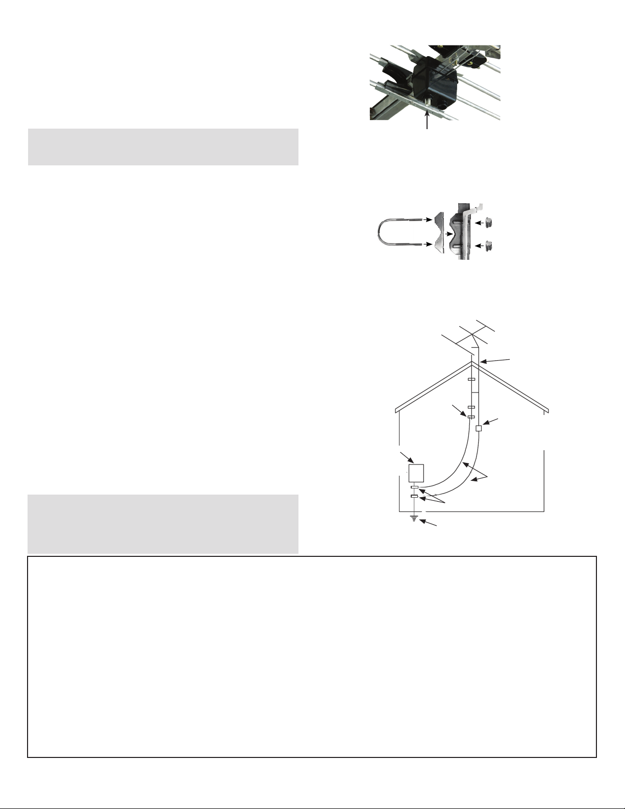
LIGHTNING PROTECTION - Example of Antenna Grounding
(as per National Electrical
Code, ANSI/NFPA 70)
NEC – Nation Electrical Code
Antenna
Downlead Wire
Ground
Clamp
Electric
Service
Equipment
Antenna Discharge Unit
(NEC Section 810-20).
May substitute a 75 ohm
coax grounding block
Grounding
Conductors (NEC
Section 810-21)
Ground Clamp
Power Service Grounding Electrode System
(NEC Art 250, Part H)
NOTE: If your coax cable has factory connectors on it, clip
small end of boot o, so boot will slip over connector.
NOTE: In the case of a “ground up” antenna installation, it may
not be necessary to ground the mast if the mast extends four or
more feet into the earth. Consult a TV serviceman for the proper
depth in your location.
STEP 8 - Coaxial Cable
A. Slide the rubber boot over the end of the coaxial cable.
B. Attach the F-connector to the coaxial cable.
C. Attach the coaxial cable to the cartridge housing. See
figure 8.
D. Slide the boot over the boot collar on the housing.
STEP 9 - Mounting Antenna to Mast
A. Loosen nuts on the main boom and boom brace mast
clamps. See figure 9.
B. Slide both mast clamps over the mast, pointing the front
of the antenna (small end) towards stations and tighten
the boom brace mast clamp securely.
C. Let the main boom mast clamp slide down the mast until
the boom brace supports the main boom. Tighten the main
boom and brace mast clamps securely.
D. To prevent wind whipping, the 75 ohm coaxial cable
downlead may be secured to the mast with tape or
plastic wire ties.
Lightning Protection for TV Antenna &Set
A. Mount the lightning arrestor or 75 ohm coaxial grounding
block as close as possible to where the 75 ohm coaxial
cable downlead enters the house.
B. The ground wires for both the mast and the downlead
should be copper or aluminum wire, number eight or
larger.
C. The downlead wire from the antenna to the lightning
arrestor and the mast ground wire should be secured to
the house, spaced four to six feet apart.
FIGURE 8 - Installing Coaxial Cable
FIGURE 9 - Mast Clamp
Attach coaxial cable with boot
Hex Nuts
U-Bolt
Mast Clamp
Insert
Mast Clamp

This manual suits for next models

1

Other Winegard Antenna manuals

Winegard Trav'ler User manual

Winegard

Winegard Trav'ler User manual

Winegard TRAV'LER DIRECTV SK-SWM3 User manual

Winegard

Winegard TRAV'LER DIRECTV SK-SWM3 User manual

Winegard Carryout PM-2000 User manual

Winegard

Winegard Carryout PM-2000 User manual

Winegard AIR 360+ User manual

Winegard

Winegard AIR 360+ User manual

Winegard In-Motion MVT-35W User manual

Winegard

Winegard In-Motion MVT-35W User manual

Winegard WX980 User manual

Winegard

Winegard WX980 User manual

Winegard HD7210P User manual

Winegard

Winegard HD7210P User manual

Winegard FreeVision User manual

Winegard

Winegard FreeVision User manual

Winegard MA1000W User manual

Winegard

Winegard MA1000W User manual

Winegard MT-4000 User manual

Winegard

Winegard MT-4000 User manual

Winegard YA7000C User manual

Winegard

Winegard YA7000C User manual

Winegard ROADSTAR RS-1000 User manual

Winegard

Winegard ROADSTAR RS-1000 User manual

Winegard RZ-6035 User manual

Winegard

Winegard RZ-6035 User manual

Winegard Carryout G2 User manual

Winegard

Winegard Carryout G2 User manual

Winegard TR-6100 User manual

Winegard

Winegard TR-6100 User manual

Winegard AS-2003 Operating instructions

Winegard

Winegard AS-2003 Operating instructions

Winegard RM-4600 Original instructions

Winegard

Winegard RM-4600 Original instructions

Winegard Carryout User manual

Winegard

Winegard Carryout User manual

Winegard YA-7000 User manual

Winegard

Winegard YA-7000 User manual

Winegard RoadTrip Mission User manual

Winegard

Winegard RoadTrip Mission User manual

Winegard DuraSAT D4 CM2000T User manual

Winegard

Winegard DuraSAT D4 CM2000T User manual

Winegard RT8000T User manual

Winegard

Winegard RT8000T User manual

Winegard SK-7003 Mount User manual

Winegard

Winegard SK-7003 Mount User manual

Winegard HD7078P User manual

Winegard

Winegard HD7078P User manual

Popular Antenna manuals by other brands

Spotwave Wireless SpotCell 100 user manual

Spotwave Wireless

Spotwave Wireless SpotCell 100 user manual

Extreme Networks Extreme Wireless Site preparation and installation guide

Extreme Networks

Extreme Networks Extreme Wireless Site preparation and installation guide

JVC KD-DB52 installation manual

JVC

JVC KD-DB52 installation manual

Velleman ANTM4N user manual

Velleman

Velleman ANTM4N user manual

Philips TT300 Product information

Philips

Philips TT300 Product information

CommScope ValuLine VHLP1 Series installation instructions

CommScope

CommScope ValuLine VHLP1 Series installation instructions

RSI TETRA user guide

RSI

RSI TETRA user guide

Cisco Catalyst IR1800 Rugged Series installation guide

Cisco

Cisco Catalyst IR1800 Rugged Series installation guide

RCA ANT1200 Specifications

RCA

RCA ANT1200 Specifications

GE Quadcore HD user manual

GE

GE Quadcore HD user manual

EPAK DS6 PRO Installation and user manual

EPAK

EPAK DS6 PRO Installation and user manual

1 BY ONE OUS00-0560 manual

1 BY ONE

1 BY ONE OUS00-0560 manual

iNetVu 1210 user manual

iNetVu

iNetVu 1210 user manual

Directive Systems & Engineering DSE1345LY quick start guide

Directive Systems & Engineering

Directive Systems & Engineering DSE1345LY quick start guide

MicroNet SP920MA-8 Quick installation guide

MicroNet

MicroNet SP920MA-8 Quick installation guide

Listen Technologies UNIVERSAL ANTENNA KIT LA-122 user manual

Listen Technologies

Listen Technologies UNIVERSAL ANTENNA KIT LA-122 user manual

Televes 534040 instructions

Televes

Televes 534040 instructions

Emos EM-HF20 quick start guide

Emos

Emos EM-HF20 quick start guide

manuals.online logo
manuals.online logoBrands
  • About & Mission
  • Contact us
  • Privacy Policy
  • Terms and Conditions

Copyright 2025 Manuals.Online. All Rights Reserved.