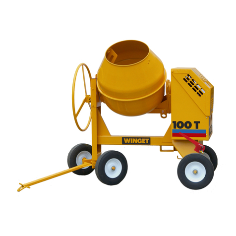
Winget 100T Service manual

MIXERS
100T 150T 175T
WINGET LIMITED, P.O. Box 41, Edgefold Industrial Estate, Plodder Lane, Bolton, BL4 0LR, England
Tel: +44 (0) 1204 854650
www.winget.co.uk
parts@winget.co.uk
150T-06045
175T-06046
110V Electric Drive From Serial Number
100T-12194
Supplement to Manual V603781
November 2021
PARTS
&
OPERATORS HANDBOOK


Page
III
IV
Safe Working 1.1
Decals 1.3
Lashing down & lifting points 1.6
Installation 2.1
Electric motors 2.10
Service schedule 3.1
Lubrication 3.2
Drum drive 3.2
Bolt torques 3.2
Page
4.1
Mixer drum sealant 4.1
Tyre pressures 4.1
Noise levels 4.1
Drum speed 4.1
Motor specifications 4.1
110V Mixer weights & dimensions 4.2
II
INTRODUCTION
Warranty
Introduction
INTRODUCTION
Section
CONTENTS
Lubricants
TECHNICAL INFORMATION
Section
OPERATION
SERVICING
components
Parts breakdowns of 110V Electric Drive
PARTS
110V Mixer wiring diagram 4.3

III
THE HANDBOOK MUST NOT BE REMOVED FROM THE MACHINE.
The Handbook must be kept clean and in good condition. Additional copies of the
Handbook can be obtained from your Distributor.
The contents of this Operator's Handbook are designed as a guide to the machine's
controls, operation, working capacities and maintenance. It is not a training manual.
Only trained operators should use this machine. Contact the C.I.T.B. or equivalent body
for advice on training.
THE HANDBOOK SUPPLEMENT-110V MIXERS
The operator must read all the Handbook and fully understand its contents
before attempting to operate the machine.
In this Handbook are WARNING notes. They are preceded by this symbol:
These notes are used to indicate the procedure being described in the
Handbook must be followed to avoid serious injury or death to yourself or to
others; or damage to the machine.
The warnings are also used to protect the machine from unsafe servicing
practices.
Pay particular attention to the warnings given in the Handbook.
If you have any doubts about any aspect of the machine's capability or servicing
procedures, you must consult the manufacturer.
The contents of this Handbook, although correct at the time of publication
may be subject to alteration by the Manufactures without notice.
Winget Limited operate a policy of continuous product development.
Therefore, some illustrations or text within this publication may differ from
your machine.
INTRODUCTION

IV INTRODUCTION
WARRANTY TERMS & CONDITIONS
The Manufacturer assures you that if any part of the machine becomes defective due to
faulty manufacture or materials within 12 months from the date of purchase, the part will
be repaired or replaced under warranty free of charge by any authorised Winget
Distributor. Warranty repairs must be carried out by Winget Distributors.
This Warranty is given to the first owner and may be transferred to subsequent owners for
the balance of the Warranty period.
The Manufacturer’s liability only extends to the costs of repair or replacement of the faulty
parts and necessary labour charges involved in the repairs. The Company accepts no
liability for any consequential loss, damage or injury, resulting directly or indirectly from
any defect in the goods.
Items not covered by Warranty and considered to be the customer’s responsibility include
normal maintenance services; replacement of service items and consumables;
replacement required due to abuse, accident, misuse or improper operation; replacement
of wearable items e.g. drive belts, pins, bushes, brake linings, clutch linings etc.
The Warranty will not apply where the equipment is modified, converted, or used for
purposes other than those for which it was designed, unless clearance for the
modifications etc. have been granted by the Manufacturer, in writing.
The Pre-Delivery Inspection and Warranty Registration Document must be completed
correctly and returned to the Manufacturer within 7 days of sale date. Failure to do so may
result in the claim being subsequently rejected.
Tyres and tubes are not covered by Warranty, but are covered by the tyre manufacturer’s
own warranty system which provides against defects in material or workmanship. Engines
are covered separately by the engine manufacturers, and engine warranty repairs must be
handled by the relevant engine manufacturers’ distributors.
No claim will be considered if other than genuine Winget Limited parts, which must be
obtained from Winget Limited via an
authorised Distributor, are used to effect a repair, or if
lubricants other than those recommended by Winget Limited are used.
The equipment must be serviced in accordance with the service schedules laid down by
Winget Limited. Evidence that these have been complied with may be required before
Warranty Claims are reimbursed.
The Manufacturer’s policy is one of continuous improvement. Winget Limited reserve the
right to change specifications without notice. No responsibility will be accepted for
discrepancies which may occur between specification of machines and the descriptions
contained in publications.

OPERATION
Safety is the responsibility of the persons working with this
machine. Think “safety” at all times.
Read and remember
the contents of this Handbook.
MACHINE MODIFICATION
Any modifications to the machine will affect its working parameters and safety
factors. Refer to the Manufacturers before fitting any non-standard equipment
or parts.
The manufacturers accept no responsibility for any modifications made after
the machine has left the factory, unless previously agreed by the
Manufacturers in writing. The Manufacturers will accept no liability for damage
to property, personnel or the machine if failure is brought about due to such
modifications, or fitment of spurious parts.
Only trained operators should use this machine.
Always be aware of local and national regulations governing the use of the
machine.
Always ensure that all guards are in position and correctly fitted.
Electrically driven mixers: Always ensure that the power supply has been
correctly connected by a qualified electrician.
Electrical cables must be of a suitably armoured type. Ensure that
they are protected from damage and not liable to cause a trip hazard
or be driven over.
Do not connect to a household socket!
Use only with an RCD protected supply. Only connect via special
feeding point (e.g. power distribution panel on building site with fault-
current-breaker).
Only authorised persons should be allowed to operate the mixer, or be in the
immediate area.
Never add lubricants to the mixer while it is running.
Never aim water from hoses and pressure washers directly at the electrical
inlet, contactor or into the motor terminal box or fan area.
Keep the area around the machine clear of obstructions, which could cause
persons to fall onto moving parts.
Keep the body and clothing clear of all moving and hot parts.
Always ensure that during operation the mixer is standing on stable and level
ground and that the wheels are chocked or the handbrake is applied.
Keep the motor housing lid closed when the electric motor is running.
Never start or stop the mixer whilst the drum is loaded.
The towing speeds of Fast Tow mixers, when used on public highways, may
be subject to local or national road traffic regulations.
1.1SAFE
WORKING

SERVING & MAINTENANCE
.
1.2 SAFE WORKING
Never allow unqualified personnel to attempt to remove or replace any part
of the machine, or anyone to remove large or heavy components without
adequate lifting equipment.
Before maintenance work is begun, ensure that the electric motor is
switched off, and isolated from the mains.
Note: Pressing the stop or emergency stop buttons on the mixer will not
isolate the machine from the mains, disconnect the incoming power supply
from the appliance inlet under the motor cover.
Always conform to service schedules except when an emergency calls for
immediate action, or adverse conditions necessitate more frequent
servicing.
Always report any defect at once, before an accident or consequential
damage can occur.
On completion of maintenance, check that the machine functions correctly,
and that all guards are correctly fitted.
Disposal of waste oil or lubricants. Dispose of waste oil into waste oil
storage tanks. If storage tanks are not available, consult your Distributor or
local authority for addresses of local designated disposal points. It is illegal
to dispose of waste oil or lubricants into drains or water courses, or to bury

Read Operators Handbook, or Operators
Handbook storage place.
Beware of electrical hazards.
Engine/Motor stop.
Attach lifting hooks to this eye
These surfaces may be hot.
Keep hands clear of drum.
Keep clear of chain or belt drives.
SAFE WORKING 1.3
DECALS
Ensure that all warning decals fitted to the mixer are legible. If any should become
detached, they must be replaced immediately.
Descriptions of the pictorial decals are as follows:

General
Care should be taken when lifting or
transporting the mixer to ensure that lifting
or retaining straps are in good condition
and the following procedures must be
followed when lifting or lashing down to
avoid causing unnecessary damage.
It is recommended that chains or webbing
slings are used to lift the mixer via the
lifting point on the trunnion and that
ratchet type webbing straps are used to
lash the mixer down.
Lifting the Mixer (Crane)
Turn the drum and trunnion through
180deg. and, using the locking pin in the
tilting handwheel, lock the assembly in this
position with the lifting eye 'A' uppermost.
Attach suitable lifting equipment to the
lifting eye and slowly take the weight. Do
not 'snatch' the mixer otherwise damage
may be caused to the lifting point, trunnion
or lifting equipment. To prevent the
drawbar swinging freely as the mixer
clears the ground, rest the drawbar’s 'T'
handle on the mainframe below the
upturned drum. If the mixer is on site and
the wheels are immersed in dried
concrete or mortar the wheels must be
freed before attempts are made to lift the
mixer. Be aware that the mixer will tend to
swing as it clears the ground.
Lifting the Mixer
(Forklift/Telehandler)
Using the tilting handwheel locking
plunger, lock the drum upright as
illustrated overleaf. If the wheels are
immersed in dried concrete or mortar, free
them before attempting to lift the mixer.
Spread the fork tines and carefully
position the forks below the mainframe so
that one
tine enters and passes through the
bracket 'B' below the mainframe, the other
fork should be spread as wide as
possible. Position the carriage as close as
possible to the mixer and rest the mixer’s
drawbar on one of the fork tines to prevent
it swinging freely.
Slowly tilt the carriage back slightly to
prevent the mixer rocking forward and
raise the mixer just clear of the ground.
Do not raise the mixer unnecessarily high,
keep the height to the minimum required
to clear any obstructions without unduly
obstructing your forward vision. When
travelling keep your speed to the minimum
and when loading vehicles do not raise
the mixer to the height of the bed until the
mixer is close to the vehicle. Similarly
when unloading vehicles lower the mixer
just clear of the ground as soon as it
clears the side of the vehicle.
1.6 SAFE WORKING
Lashing down & Lifting points

Lashing Down
It is recommended that unless the mixer is
pulled up against a headboard or some
form of substantial wheel chocks that two
ratchet type webbing straps are used to
retain the mixer, one pulling to the rear
and one pulling to the front. The drum
should be locked in the upright position
shown above to keep the centre of gravity
as low as possible.
Position the mixer on the vehicle bed and
chock the rear wheels or apply the
handbrake to prevent it rolling until lashed
down. Turn the front axle so that the
drawbar is below the mixer and not
forming an obstruction on the vehicle bed.
Lock the drum in the upright position.
Pass one of the webbing straps between
the drum and trunnion at point 'C' and
secure the strap down to retaining hooks
on the vehicle bed in front of the mixer.
Pass the second strap between the drum
and trunnion at point 'D' and secure the
strap down to retaining hooks on the
vehicle bed to the rear of the mixer.
Tighten the straps by means of the
ratchets until the mixer is securely held.
SAFE WORKING 1.7

INSTALLING THE MIXER ON SITE
Welded to the mixer are lifting points.
These are provided to assist with loading
or unloading the mixer and for
transportation across site.
For mixer weights, see
"Specifications"
Never carry mixers by their lifting points
on public roads.
Do not tow four wheeled mixers across
uneven ground.
The ground on which the mixer stands
must be level and stable. Ensure that the
wheels are chocked or the handbrake is
applied.
Stop the motor and disconnect the
electrical supply before attempting to
move the mixer.
Electrically driven mixers:
Always ensure that the power supply is
correctly connected or disconnected to
and from the appliance inlet using a
suitable cable and plug which is in good
condition without exposed wiring or
damaged plugs.
Electrical cables must be of a suitably
armoured type. Ensure that they are
protected from damage and are not liable
to cause a trip hazard or be run over.
Do not connect to a household socket!
Use only with an RCD protected supply.
Only connect via special feeding point
(e.g. power distribution panel on building
site with fault-current- breaker).
If connecting via a transformer it’s rating
must be adequate to power the motor
Electric motors
To start and stop:
Gain access to start button by raising the
motor housing cover (50).
Start the motor by pressing the green
button (51). Lower the motor cover (50).
To stop the motor, raise the cover (50)
and press the red button (52). (Pressing
button (53) located on the rear cover or
closing plate will also stop it.)
In an EMERGENCY, press
button (53) located on the rear
panel to stop the motor.
Pressing buttons (52) or (53)
will not isolate the mixer from
the mains. The supply must be
disconnected from the
appliance inlet under the cover
(50)
2.1 OPERATION

SERVICE SCHEDULE
Every day
Links, shafts & hinges: Lubricate.
Every week (or 50 hours running) The above and following items
Nuts, bolts and keys. Tighten (Each week for first month):
Drive belts: Check V belt tension .
Drum Bevel Gears: Lubricate with open gear fluid.
Every 125 hours. The above and following items
Motor: Clean fan and air inlet
Every 250 hours. The above and following items
Nuts, bolts & keys: Tighten.
SERVICING 3.1

SERVICING PROCEDURE
Lubrication
It is essential that oils and
grease used for servicing do
not become contaminated
with sand or cement dust.
Every day
Apply a little engine oil to pins, joints and
hinges, wheel shafts etc. to ensure that
they move easily and are free from
corrosion.
Drum drives
Every week (or 50 hours running)
Drive chains:
Lubricate drive chains (A) with a little
engine oil through the oiler on top of the
trunnion journal.
Drum drive
Drive belts:
NEVER oil belts.
Check the tension of the belt and adjust if
necessary. The belt should deflect no
more than 2 to 3 mm using thumb
pressure.
Never over-tighten the belt as this will put
excessive strain on engine bearings
causing vibration and wear.
Bolt torques
Every week for the first month, then
every three months
Check the tightness of all bolts, nuts, and
keys etc. Pay particular attention to motor
mounting bolts.
3.2 SERVICING

Lubricants
Mixers are factory filled with the following TOTAL oils or equivalents
Electric motor bearing (where fitted) Multis EP 2
Drive chain Rubia B 20W/30
Bevel gear & pinion Open gear fluid
Drum shaft Anti-seize compound
Grease nipples (where fitted) Multis EP 2
Shafts, linkages and hinges Rubia B 20W/30
Noise levels of mixers.
Measured in accordance with EC Directive 2000/14/EC & UKSI 2001/1701
Models 100T, 150T and 175T
LWA 90
LPA 71 @ 1m drum empty
Drum speed Handbrake
20-22 rpm Tested to hold on a 5° & 10° slope with 600Kg of test weights applied
Tyre pressures
50 lbin2 (Two wheeled “Fast tow” mixers)
Mixer drum sealant
Silicone sealant (part number V2000772)
Motors
Electric motors
110v
@ 1420 rpm
100T 1.5kW (2.0hp)
150T 1.5kW (2.0hp)
175T 1.5kW (2.0hp)
TECHNICAL INFORMATION 4.1
IP Rating
Minimum IP Rating IP44

DIMENSIONS
4.2 TECHNICAL INFORMATION
100T 150T 175T
A1805 1890 2060
B2390 2490 2640
C1610 1760 1840
D565 600 590
E1325 1325 1350
F4.80/4.00-8 145R10
G1035 1140 1180
H490 490 450
Weight (approx) 110V
100T 150T 175T
350kg 405kg 445kg
100T 150T 175T
A1515 1650 1680
B1560 1730 1780
C 520 555 520
D 800 800 800
E 400 400 400
F1000 1100 1110
Weight (approx) 110V
100T 150T 175T
325kg 385kg 405kg

ELECTRICALLY DRIVEN MIXERS WIRING CIRCUIT-SCHNEIDER CONTACTOR
Electrical connections must only be made by a suitably qualified/competent person
or electrician.
TECHNICAL INFORMATION 4.3

PARTS
110V Mixers
100T
150T
175T


Other manuals for 100T
4
This manual suits for next models
2
Table of contents
Other Winget Mixer manuals

Winget
Winget 200T User manual

Winget
Winget 300R Instruction manual

Winget
Winget CUMFLOW RP50XD MK2 User manual

Winget
Winget 100T Instruction manual

Winget
Winget 100T Service manual

Winget
Winget CUMFLOW RP150XD MK2 User manual

Winget
Winget 200T Instruction manual

Winget
Winget Croker CUMFLOW RP100XD User manual

Winget
Winget 200TM Instruction manual

Winget
Winget 200T Service manual