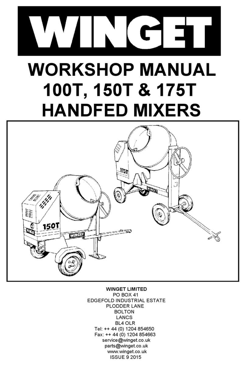
WORKSHOP MANUAL
100T / 150T / 175T
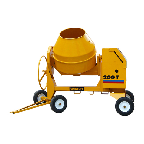
Winget Concrete Mixers
From 2015 Onwards
Issue 1 2021
supported only on a jack. Remove the wheel nuts and wheel assembly. Unbolt
and remove the mudguard and supporting bracket. Remove the remaining
bolts securing the suspension unit and detach the unit from the mainframe.
Note: it is recommended that suspension units be replaced in pairs.
Reverse the procedure to refit.
Wheel Hubs & Bearings-Two Wheel Tow
A single castle nut and flat washer retains the hubs to the stub axles of the
suspension units. The castle nut is also secured with a split pin; this is
accessible after removing the steel/plastic dust cap.
The bearings are automotive type taper roller bearings requiring a small
amount of end float.
To remove the hubs remove the wheels as described above, prise off the dust
caps. Remove the split pin, nut and washer and pull off the hub. Do not allow
the taper roller or ball bearings to drop to the floor where they will become
contaminated with dust etc. The later type inner taper roller bearing and seal
unit will normally be left on the stub axle when the hub is withdrawn, this can
be carefully tapped off using a suitable drift taking care not to damage the
bearing cage.
Clean all traces of old grease out of the hubs and off the stub axles, using a
suitable drift knock out the old bearings, pack the new bearings with grease
and tap home into the hub.
To adjust the taper roller bearings, tighten the nut then back off 1/4-1/2 a turn,
check that the hub spins freely without to much end float, .004” is sufficient.
Align the castle nut with the split pinhole in the stub axle and fit the retaining
split pin. Recheck the hub rotates freely and refit the dust cap. Charge the hub
with grease until the grease is visible in the breather hole in the cap.
It is recommended that the wheel bearing adjustment be rechecked after
giving the mixer a short “road test”.
Front Axle Replacement- Four Wheel Tow
The front axle is designed to rotate through 360, it does not oscillate and the
front axle swivel pin locates directly into the front leg of the mainframe where it
is secured via a spiral pin.
Jack up and support the mainframe and knock out the spiral pin. Remove the
axle. Replacement is a reversal of the procedure however the pivot pin and
