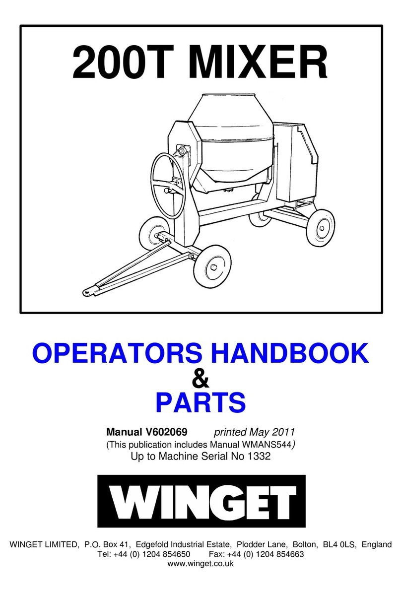
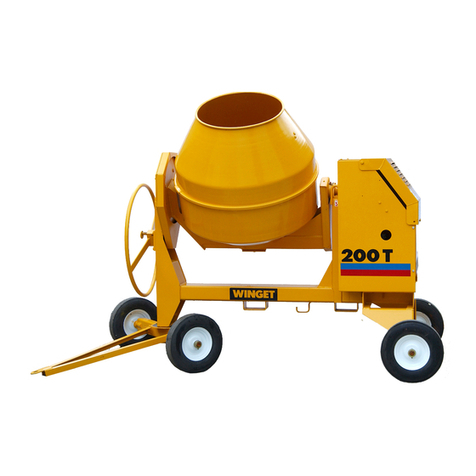
Winget 200TM Instruction manual

WORKSHOP MANUAL
200TM
MIXER
WINGET LIMITED
PO BOX 41
EDGEFOLD INDUSTRIAL ESTATE
PLODDER LANE
BOLTON
LANCS
BL4 OLR
Tel:- ++ 44 (0) 1204 854650
www.winget.co.uk
FROM
1998 ISSUE 8

WORKSHOP MANUAL
Winget Mechanically Fed Mixers
Models: 200TM
From 1998
CONTENTS
Section 1 Introduction
Section 2 Repair and Service Procedures
Section 3 General Arrangement Dimensions
Section 4 Service Schedules
Lubrication Diagram
Section 5 Hydraulic Circuit Diagrams
Section 6 Wiring Diagrams
Section 7 Noise Levels
Section 8 Special Tools
Section 9 Hydraulic Control Valve
Service Manual (Where available)
Section 10 Parts Listings
Section 11 Batchweigher Maintenance Instructions
Section 12-18 Blank

WORKSHOP MANUAL
200TM
SECTION 1
INTRODUCTION

WORKSHOP MANUAL
Winget Mechanically Fed Mixers
Models: 200TM
From 1998
Introduction
It is assumed that Personnel involved in either the Assembly or repair of Winget
Mixers will be familiar with the product, either through the operation of, or previous
repair and maintenance work. It is not intended to be used by Personnel who are
neither familiar with the product or mechanically inexperienced.
It is also assumed that personnel are aware of the Health and Safety Regulations,
which should be applied to all working practices, but the following should act as a
reminder.
Ensure all work tools are in good condition.
Always wear Safety Spectacles when using Soft or Hard Faced Hammers, Chisels or
when using Air Tools. Wear Safety Spectacles when cleaning Hardened Concrete or
Mortar off components.
Do not misuse Air Lines and be aware of the damage Compressed Air can cause if
misused.
Always make sure Lifting Equipment is in good condition and the Safe Working
Loads exceed the weights of the components to be lifted.
Oils, Fuels, Silicone Sealer and Open Gear Lubricants can cause skin diseases if
allowed to contaminate the skin. Always apply barrier creams, wear suitable
protective clothing or when contamination is unavoidable clean the area with soap
and water as soon as possible. Do not use thinners or other solvents to clean skin.
Health and Safety is a matter of common sense. If common sense is applied
correctly Health and Safety can be improved upon and the risk of accidents reduced.
L/H and R/H views are taken when standing directly behind and facing the engine
housing.
Whilst every effort is made to ensure the contents of this manual are accurate,
Winget Limited accept no responsibility for errors or omissions and reserve the right
to alter specification without prior notification and certain sections may then no longer
apply.
Repair & Maintenance Procedures
The following procedures are based in part on the procedures issued to Distributors
and the instructions should be used in conjunction with the appropriate Parts and
Operators Manual or Parts Microfiche. Reference should also be made to the Parts
Listings in Section 10 for a guide to the correct sequence for assembling components
and sub assemblies.

WORKSHOP MANUAL
Winget Mechanically Fed Mixers
Models: 200TM
From 1998
1) Clean any paint or debris from bores and shaft surfaces. Threaded holes
should preferably be cleaned out using the correct tap
2) All sealed for life bearings should be packed with a good quality grease prior to
installation. Carefully remove a seal, pack the bearing with grease and refit the
seal ensuring it is correctly seated.
3) Apart from installing the electric motor, mounting brackets and conduit as
described in this manual under the heading ‘415 volt 3 ph Electric Motor’ all
wiring and other work concerned with the installation of 415 volt components
and supply should be left to a suitably qualified electrician, who is conversant
with 3 ph 415 volt electric circuits.

WORKSHOP MANUAL
200TM
SECTION 2
REPAIR & SERVICE
PROCEDURES

WORKSHOP MANUAL
Winget Mechanically Fed Mixers
Models: 200TM
From 1998
Lifting Points
Lifting points capable of supporting the weight of the mixer are incorporated in both
the rear leg of the mainframe and on the upper leading edge of the hopper cradle.
The lifting points are highlighted with an ISO ‘Hook’ symbol adjacent to each point.
On Military/Nato mixers the lifting points are also painted white.
The hopper also incorporates lifting points to assist in removing the hopper. The
hopper lifting points are not highlighted to avoid confusion with the main lifting points.
On no account must the hopper lifting points be used to support the weight of the
mixer.
Pneumatic/Steel Wheel Replacement.
The pneumatic or steel wheels are secured to the axle stub shafts using a collar
retained via a long bolt and binx nut. To replace a wheel jack up and support the axle
adjacent to the stub shaft, undo and remove the retaining bolt slide off the collar
followed by the wheel. Pneumatic wheels are fitted with a removable needle bearing,
which can be grease via the grease point. Reverse the procedure to replace a wheel
not forgetting to lubricate the stub shaft and needle bearings with grease prior to
assembly.
Axles Front & Rear.
Using suitable lifting equipment lift and support the mainframe. The Rear axle is
retained to the mainframe using four bolts, flat washers and binx nuts. Remove the
bolts and carefully manoeuvre the axle clear off the frame. Reverse the procedure to
refit.
The front axle is retained via a pivot pin, washers and split pins, to remove lift and
support the mainframe using suitable lifting equipment. Straighten the split pins and
remove from the pivot pin. Using a suitable drift and hammer knock the pivot pin up
through the axle and manoeuvre the axle clear. Reverse the procedure to refit not
forgetting to coat the pivot pin with anti-seize compound and fit new split pins. The
axle is prevented from rotating to far by the use of two M10 set screws as axle stops
if the axle is changed do not forget to replace the stop screws.
Lower the mainframe and allow to stand on the wheels, if pneumatic wheels are fitted
check and adjust the tyre pressures.

WORKSHOP MANUAL
Winget Mechanically Fed Mixers
Models: 200TM
From 1998
Drawbar-Standard
The standard drawbar is attached to the front axle via two bolts, flat washers and binx
nuts, to remove simply undo and remove the bolts and lift the drawbar clear. Reverse
the procedure to refit.
Drum Removal
Attach suitable lifting equipment through the Drum Blades. Knock back the tabs on
the tabwasher securing the Drum Shaft setscrews. Remove the setscrews and
washers securing the Shaft and Flange. With the Drum Mouth upright lift the Drum
assembly clear of the Trunnion. It may be necessary to rock the Trunnion via the
Tiltwheel to free the Drum Shaft.
In exceptional circumstances it may be necessary to use a Two-Leg Puller/Pusher
Tool to assist in pushing the Drum Shaft through the Trunnion. When using such
tools follow the manufacturers instructions.
Replacement of Drum Shaft, Bevel Gear and Bearings
Remove the drum as described previously and turn upside down so that the
assembly stands on the open mouth of the drum. Before removing the bevel gear
from the drum base use suitably sized circlip pliers and remove the large circlip
retaining the lower shaft bearing into the gear.
Remove the setscrews securing the bevel gear and shaft assembly to the drum base,
use two of the setscrews as jacking as screws utilising the threaded holes in the
bevel gear and jack the assembly out of the base.
With the assistance of suitable lifting equipment lift the assembly onto a suitable
supporting surface and using a soft faced hammer or mallet knock the shaft back
through the bevel gear. Support the shaft in a suitable soft jawed vice and remove
the smaller circlip from the end of the shaft retaining the upper drum bearing, using a
suitable drift or puller remove both bearings from the shaft. Clean all the components.
Before fitting new bearings carefully remove the seals from the bearings and pack
the bearings with good quality grease, refit the seals, do not completely fill the
bearings with grease leave some room for expansion as the grease warms up in
service.
Fit the new bearings to the shaft and retain the upper smaller bearing using a new
circlip. Clean out the drum centre shaft housing and smear a little anti-seize
compound round the circumference of the upper bearing seat within the housing.

WORKSHOP MANUAL
Winget Mechanically Fed Mixers
Models: 200TM
From 1998
Place the bevel gear on the drum base and loosely retain with the setscrews and
washers, apply threadlock to the screw threads before inserting, smear a little anti-
seize compound round the circumference of the lower bearing seat in the bevel gear.
Lower the shaft through the bevel gear and using a suitable mallet or soft faced
hammer knock the shaft fully home, fit the large retaining circlip and finger tighten
the setscrews.
(Once the setscrews are tight it may be necessary to give the shaft end a sharp tap
to fully seat the bearings.) Check the gap between the bevel gear and drum base
(due to manufacturing tolerances) and pack using the shims around the
circumference of the gear in 6/8 positions. Tighten the retaining screws. Seal round
the edge of the bevel gear using a suitable sealer.
Drum Cone Replacement, Diesel TS/TR1 Engine
Clean hardened concrete or mortar from around the drum clip and bolts securing the
drum blades. Remove the bolts securing the blades to the drum cone and slacken
the bolts through the base. Cut through the drum clip and remove. Lift off the drum
cone. If necessary clean out the drum base. Clean any old silicone sealer and
hardened concrete from the drum flange.
The 200T and 200TM both utilise the same drum cone, however because the
TS/TR1 diesel version of the 200TM rotates in the opposite direction to the 200T and
electric
driven 200TM different drum blades are used. The standard cone must therefore be
modified prior to use as follows.
Using the special template/tool available from Winget under part number 513360100,
(a drawing is enclosed in the ‘special tools section) insert the template into the
existing holes in the cone and mark out the new upper holes.
Remove the template and drill the two new holes, weld up the existing upper holes,
the cone is now ready for fitment.
Run a generous bead of silicone sealer around the flange of the drum base and
inside the new drum clip. Leave the last 150mm of each end of the clip free from
sealer.
Using suitable lifting equipment lift the new drum cone in place lining up the holes in
the cone with those in the blades. Loosely refit in the bolts, nuts and washers. Fit
the new drum clip around the circumference of the two halves of the drum tapping in
place over the flanges using a soft faced hammer.
Attach the special drum clip tool placing the pins on the tool into the holes in each
end of the clip.
Using a suitable spanner tighten the drum clip to the drum until it is secure. Do not
overtighten the clip or the pins in each end of the tool will shear off. Slip the bridge
200TM DRUM CLIP FIXING
AFTERCOATINGTHEMATINGFACESOFTHEDRUM
BASEANDCONEWITHSILICONESEALERFITTHE
CLIPAROUNDTHEDRUMASSHOWN.RUNABEAD
OFSEALERINSIDETHEDRUMCLIPPRIORTO
FITMENTLEAVINGAPPROXIMATELY6’’(I50mm)
EACHENDOFTHECLIPCLEAROFSEALER.CLAMP
THECLIPINPLACEUSINGTHESPECIALTOOL
NUMBER513204000.FITTHEBRIDGEPIECEIN
PLACEOVERTHEGAPLEFTINTHECLIPANDWELD
INPLACE

WORKSHOP MANUAL
Winget Mechanically Fed Mixers
Models: 200TM
From 1998
piece over the remaining gap in the drum clip and weld in place. Remove the tool.
Fully tighten the drum blades.
Run the mixer, tilting the drum via the tiltwheel making sure that the drum, clip or
bridge piece do not foul the mainframe or guards.
Stop the engine, clean any excess silicone off the drum or clip.
Drum Blade Replacement
It is unlikely that drum blades will require replacement separately to the drum cone.
However in the event that it should prove necessary, clean any hardened concrete or
mortar from around the bolts securing the blades. Remove the bolts and blades. Due
to the corrosive action of concrete and mortar it may be necessary to cut through the
old bolts using oxyacetylene equipment. Be aware that hot concrete can “explode”
violently spitting concrete - wear suitable eye protection and protective clothing.
Attach the new blades into the drum assembly finger tighten the bolts until all the
bolts are in place. Tighten the bolts.
The bolts should go into the drum from the outside and only round or dome headed
bolts should be used.
Bevel Gear Guard Replacement
Remove the drum assembly as previously described. Remove the four setscrews,
nuts, etc. holding the guard in place. Fit the new guard tighten the setscrews.
Replace the drum assembly as described below.
Refitting Drum Assembly
Using suitable lifting equipment lift the drum assembly, check the drum shaft is clean
and referring to the Drum Adjustment illustration coat the drum shaft (J) and trunnion
with anti-seize compound at (A).
Turn the drum shaft so the threaded holes in the base of the shaft are at 90 degrees
to those in the trunnion base blocks.
Position the drum over the trunnion and lower into place making sure the bevel gear
and pinion are fully in mesh and the drum is fully seated down.
Apply anti-seize compound to the drum shaft setscrews and secure the flange to the
drum shaft not forgetting the tabwasher. Using the flange turn the drum shaft until
the remaining holes in the flange align with the holes in the base block.

200TM DRUM ADJUSTMENT

WORKSHOP MANUAL
Winget Mechanically Fed Mixers
Models: 200TM
From 1998
Refer to the Drum Adjustment illustration and check the number of flat washers
required to fill the gap (G) between the flange and base block. Remove one washer
from each side. Apply anti-seize compound to the setscrews (H) and pass the
setscrews through the flange and flat washers, fully tighten the setscrews into the
trunnion.
Check for free play between the drum bevel gear and bevel pinion (C) by gently
rocking the drum (approximately 3mm is acceptable). By using a combination of the
varying thickness of washers and shims it is possible to fine tune the backlash.
Remove the lifting equipment.
Tilting Handwheel and Locking Plunger
The tilting handwheel wheel is secured to the tilting pinion via a feather key and M10
grubscrew. With the drum in the vertical position slacken and remove the grub
screw, pull off the handwheel. Note on mixers, which have been in service for some
time it may be necessary to use a suitable puller on the handwheel.
The locking Plunger is held in place in the Tilting Wheel by a small spiral pin. Knock
out this pin and remove the locking plunger.
Re-assemble in the reverse order coating the locking plunger and pinion shaft with
anti-seize compound.
Tilting Bracket and Pinion
With the Drum in the vertical position remove the lower tilting pinion guard. Remove
the four setscrews securing the tilting bracket taking care not to drop the retaining
plate on the inside of the mainframe front leg. Lift the pinion teeth clear of the tilting
chain, remove the inner retaining bracket and lift out the tilting bracket assembly.
Remove the handwheel as described above, remove the feather key and using a soft
faced hammer knock the tilting shaft and pinion out of the bracket. Check the
condition of the bushes and replace and/or lubricate as required. Note, very
occasionally new bushes will require reaming to size.
Reassemble the tilting bracket in reverse order lubricating bushes with engine oil.
Coat shafts, pinions and plungers with anti-seize compound.
When refitting the tilting bracket assembly to the mixer engage and lock the plunger
into the lower single hole in the bracket whilst ensuring the drum is still vertical.
Pass the assembly through the front leg of the mainframe, slip the retaining plate
over the bracket before engaging the pinion into the tilting chain.
Align the bracket and inner retaining plate with the slots in the front leg and insert the
setscrews and washers. Finger tighten the setscrews to hold the bracket in place and
slide the assembly in the slots to correctly tension the tilting chain, fully tighten the
four setscrews. Refit the lower tilting pinion guard.

WORKSHOP MANUAL
Winget Mechanically Fed Mixers
Models: 200TM
From 1998
Turn the handwheel and check the drum and trunnion operate correctly and contact
the travel stops without unduly stressing the tilting chain.
Tilting Chain
To access the tilting chain remove the upper and lower chain guards behind the front
plate of the trunnion. The chain is anchored to the trunnion end plate by means of
two split links one in each end of the chain.
To replace the chain, place the drum in the vertical position and engage the
handwheel locking plunger in the lower single hole. Slacken the four setscrews
retaining the tilting bracket and lift the bracket in the slots to release any tension on
the chain, tighten at least one of the setscrews to hold the bracket in place. Separate
the split links and unhook the chain. Reverse the procedure to refit the chain
adjusting the final chain tension by sliding the tilting bracket in the slots. Refit the
guards and check the trunnion contacts the travel stops without unduly stressing the
chain.
Countershaft/Bevel Pinion Drive Chain.
Remove the chain guard from the rear of the trunnion. Crank the engine over until the
chain split link is visible. Disconnect the split link, hook the new chain loosely onto the
split link slowly crank the engine and pull the new chain in place round the
countershaft sprocket. Remove the old chain and link. Loop the new chain round
the sprocket in the bevel pinion shaft and fit the new split link. The open end of the
split end should point away from the normal direction of rotation, which is anti-
clockwise when looking directly at the chain. Check and adjust the chain tension.
(See Bevel Pinion Shaft and Housing). Refit the chain guard.
Bevel Pinion Shaft and Housing
Follow the procedures described earlier and remove the drum, bevel gear guard and
disconnect the countershaft bevel pinion drive chain.
Rotate the trunnion until it reaches its highest point and lock in place. Remove the
gib head key securing the sprocket to the bevel pinion shaft. Remove the bevel
pinion guard, release the tabwashers and remove the setscrews, packers and shims
securing the bevel pinion housing. At this point the bevel pinion housing should be
supported by a second pair of hands, strapped or supported in some other manner to
prevent it dropping down sharply and causing damage to the casting, it will otherwise
only be secured by the loose fitting retaining plate and sprocket.
Remove the nuts and washer off the two bolts retaining the bevel pinion housing
adjusting plate. Using a soft faced hammer knock the bevel pinion shaft through the
sprocket until it is possible to remove the sprocket. Remove the bolts through the
retaining plate and lift the bevel pinion housing out of the trunnion.

WORKSHOP MANUAL
Winget Mechanically Fed Mixers
Models: 200TM
From 1998
Clamp the housing in a soft jawed vice and remove the gib head key retaining the
bevel pinion and pull off the bevel pinion.
Remove the circlip from the groove within the housing and using a soft faced
hammer knock the shaft and bearings out of the housing. The bearings can now be
removed from the shaft.
Carefully remove the seals from the bearings and pack the bearings with good quality
grease, refit the seals, do not completely fill the bearings with grease leave some
room for expansion as the grease warms up in service.
To reassemble secure the bevel pinion shaft into a soft jawed vice. Using the correct
size of Bearing tube and a soft faced hammer or suitable drift fit the bearings to the
shaft. Note the larger of the two bearings is fitted to the longer shank of the shaft.
Remove the shaft from the vice and using the vice support the bevel pinion housing.
Using the correct size of bearing tube or suitable drift and the soft faced hammer
knock the shaft fully into the housing. Fit the retaining circlip into the groove within
the housing. Check the shaft turns freely.
Assemble the bevel pinion to the shaft, fitting the gib head key. The pinion is fitted to
the longer shank of the shaft. If correctly assembled the threaded holes in the
casting will be at the same end. Do not at this stage fit the sprocket to the opposite
end of the bevel pinion assembly, as this will prevent re-assembly of the housing
back into the trunnion.
Loosely fit the triangular adjusting plate back into the trunnion, locating the plate on
the peg. Fit the two bolts through the adjusting plate from the rear of the trunnion so
that when assembled the head of the bolts will be sandwiched between the trunnion
rear plate and the bevel pinion shaft drive sprocket.
Work the bevel pinion housing back into the trunnion and through the adjusting plate.
As the shaft protrudes through the rear of the trunnion slide on the sprocket until it is
fully home.
Refit the setscrews, tabwashers, packer and shim set retaining the bevel pinion
housing and finger tighten only.
Fit the gib head key retaining the drive sprocket and refit the drive chain, when
connecting the split link the open end of the link should be fitted so that it points away
from the normal direction of rotation which is anti-clockwise when looking directly at
the chain.
Release the trunnion and turn back to its lowest position.

WORKSHOP MANUAL
Winget Mechanically Fed Mixers
Models: 200TM
From 1998
Refer to the Drum Adjustment illustration. The Adjusting Plate holding the rear of the
Bevel Pinion Housing (D) is slotted to allow the Housing to move up and down
enabling correct adjustment of the chain tension (F). Check and adjust the Chain
Tension and tighten the bolts holding the Adjusting Plate. By adding or subtracting
shims (E) between the thick packer and the Bevel Pinion Housing ensure the
housing is horizontal in the Trunnion and square to the rear plate. Re-check the
Chain Tension and fully tighten the bolts and setscrews securing the Bevel Pinion
Housing (D), knock over the Tab Washers.
Crank the engine ensuring both the countershaft and bevel pinion turn freely. Coat
the bevel pinion with open gear lubricant and fit the pinion guard. Fit the rear chain
guard.
Following the procedures described earlier refit the Bevel Gear Guard and Drum
Assembly.
Countershaft, Trunnion Journal and Driven Chainwheel/ ‘V’ Pulley
Although it is recommended that the trunnion is removed completely from the mixer
should the countershaft or trunnion journal require attention it is possible to leave the
trunnion assembly in place provided it is properly supported.
Remove the engine housing lid, top plate, engine housing chain guard and infill plate.
Slacken the two bolts through the bevel pinion housing adjusting plate and the two
setscrews which secure the casting at the pinion end to release the tension on the
countershaft chain.
Disconnect the split links retaining both the engine drive and countershaft chains and
remove the chains. On electric drive mixers the drive is transmitted to the
countershaft by means of a ‘V’ belt in place of the chain.
Withdraw the gib head key retaining the driven chainwheel/’V’ belt pulley to the
countershaft and pull off the chainwheel/pulley.
Lock the drum in the vertical position using the handwheel locking plunger and using
suitable lifting equipment, jacks or chocks secure the trunnion to prevent it moving
when the journal is withdrawn.
Remove the two setscrews retaining the journal casting to the mainframe, take the
weight off the trunnion and withdraw the journal from the trunnion.
Support the assembly in a soft jawed vice, remove the circlip retaining the
countershaft sprocket and pull off the sprocket, remove the feather key.
Remove the circlip in front of the bearing and using a soft faced hammer and suitable
drift knock the shaft out of the journal from the opposite end.

WORKSHOP MANUAL
Winget Mechanically Fed Mixers
Models: 200TM
From 1998
Remove the bearings and clean all the components. Carefully remove the seals from
the new bearings and pack the bearings with good quality grease, refit the seals, do
not completely fill the bearings with grease leave some room for expansion as the
grease warms up in service.
Reverse the procedure to re-assemble using a suitable bearing tube or drift to seat
the front bearing into the housing, retain with the circlip. Pass the countershaft (end
with feather key way and circlip groove) through the housing and into the bearing and
knock fully home using a soft faced mallet or hammer. Fit the second bearing over
the shaft and knock fully home using a bearing tube or drift until it contacts the
shoulder on the shaft.
Fit the feather key, slide on the small sprocket and retain with the circlip. Smear a
little grease around the circumference of the trunnion/journal bearing face and in the
bore of the corresponding bearing boss on the trunnion. Slide the journal fully home
into the end of the trunnion and retain using the two setscrews. Remove the chocks,
lifting equipment or jacks and tighten the setscrews fully.
Coat the end of the countershaft with anti-seize compound and slide on the
chainwheel/’V’ belt pulley, pushing fully onto the shaft, fit the gib head key.
Refit both the countershaft chain and the engine chain/’V’ belt, ensuring that the open
end of the split links point away from the normal direction of rotation.
Adjust the countershaft chain tension (refer to the ‘drum adjustment illustration’ and
‘bevel pinion housing’) and tighten the bevel pinion housing, check the engine drive
chain tension or ‘V’ belt pulley tension, adjust the tension as necessary. On diesel
engines adjust the shimming below the engine (see ‘engines’), on electric drive
machines move the motor either upwards or downwards on the threaded adjusters
as required. (see 415v motors)
Fit the infill plate, chain guards and plastic plug, top plate and engine-housing lid.
Release the locking plunger and operate the handwheel ensure the trunnion tilts
correctly, start the engine and check the operation of the drum drive, also check for
unusual noises.
Front Trunnion Bearing Replacement
Lock the drum and trunnion in the vertical position using the handwheel locking
plunger. Using suitable lifting equipment, jacks or chocks support the trunnion just
behind the front leg of the mainframe.
Remove the two nuts and washers securing the profiled retaining plate, take the
weight of the trunnion and pull off the plate and bearing boss. Clean all parts.
Reverse the procedure to refit, not forgetting the grease nipple which also prevents
the bearing from turning. Remove the chocks, jacks or lifting equipment.

WORKSHOP MANUAL
Winget Mechanically Fed Mixers
Models: 200TM
From 1998
Trunnion Removal/Replacement
Remove the drum, engine housing lid, top plate, chain guards and infill plate in the
engine housing. Remove the upper and lower tilting chain guards and remove the
tilting chain. Remove the engine drive chain, undo and remove the two setscrews
retaining the journal and the two nuts securing the front bearing, attach lifting suitable
equipment to the trunnion and take the weight, remove the front bearing.
Note, to remove the trunnion fully it will be necessary to rotate the trunnion as it is
being lifted in order for it to clear the engine housing.
Slide the trunnion towards the engine housing until it can be seen that the travel stop
pegs welded in the front leg and trunnion end plate are clear of each other, rotate the
trunnion and move backwards and upwards to clear the engine housing.
Place the trunnion on a suitable surface and remove the bevel pinion housing and
journal as previously described.
When replacing a 200TM trunnion ensure it has three travel stop pins, part no
513310000 welded into the front plate.
Reverse the procedure to rebuild the trunnion and refit it into the mixer referring to
the relevant sections to set up bevel pinion, journal, front bearing, drum etc.
Hydraulic Hopper Ram
The single acting hopper ram is retained via two pivot pins, to remove fully raise the
hopper and engage the hopper support. Disconnect the hydraulic hoses, note later
rams have a return hose vented back to the hydraulic tank whilst earlier rams have a
small breather hole open to atmosphere. Support the weight of the ram and remove
both pivot pins lift the ram clear of the mainframe.
If installing a seal kit note that later rams vented back to tank have additional wiper
and pressure seals fitted in the cylinder end cap. Also some machines do not have a
loose travel restrictor in the form of a small spacer installed on the piston rod.
Reverse the procedure to refit the ram coating the pivot pins with anti-seize
compound and not forgetting to install the grease nipples, straight into the cylinder
base, 90 degree angled into the piston rod.
Refit the hoses, start the engine or motor and slowly extend the piston via the control
valve, the movement may be ‘jerky’ as the system will be contaminated with air, refit
the upper pivot pin and continue to extend the rod to raise the hopper, disengage the
hopper support and lower the hopper. Stop the engine motor and top up the hydraulic
oil tank. Start the engine/motor and lower and raise the hopper a number of times to
fully expel all the air from the system.

WORKSHOP MANUAL
Winget Mechanically Fed Mixers
Models: 200TM
From 1998
EC machines, which are “CE”, marked are fitted with a hose burst valve to protect the
operator in the event of a hose failing.
The valve are pre-set on leaving the factory fitted to a machine but occasionally
require adjusting as they wear in service. To adjust, ensure the hopper is lowered
and any residual hydraulic pressure has been dissipated by operating the control
lever a number of times with the engine/motor stopped. Remove the valve from the
ram noting which way round it was installed, the body is marked. Unscrew the inner
baffle assembly, noting which way it was installed and adjust the baffles by holding
the nut and turning the capscrew with a hexagon key until the gap between the
baffles measures 0.889mm.
The valve should then be re-assembled and screwed onto the ram, ensuring the
valve is the correct way round. Fit the hydraulic adapter and bonded seal coating the
threads with hydraulic sealer. See Service Bulletin in SB100 for further details on the
valve.
Note, position the assembled ram into the mainframe so that the fitting/hose burst
valve face the L/H side (hopper cradle) of the mainframe.
New valves supplied or received as a spares item should be dismantled before fitting
and the inner baffles adjusted by holding the nut and turning the capscrew with an
hexagon key until the gap between the baffles measures 0.889mm.
It is quite common for machines fitted with hose burst valves to ‘lock out’ in service
with the result that a raised hopper will not lower. Operating the control lever in a
‘violent’ manner to shake material free is the major cause of ‘lock outs.’ To release a
‘locked out’ hose burst valve slowly and gently operate the control lever to raise the
hopper, this will blow off the ‘locked out’ valve allowing the hopper to be gently
lowered approximately 150mm following which the hopper can be used as normal.
Hydraulic Tank
The hydraulic tank is mounted below the cover on the side of the engine housing. To
gain access to the suction strainer or clean the filler breather it will be necessary to
remove the cover and the open up the tank via the removable circular cover located
on top of the tank.
The suction strainer is screwed onto the suction fitting inside the tank and should be
removed and cleaned in accordance with the service schedules. A drain plug is
provided below the tank assisting oil changes, and the tank can be quickly removed
should it be necessary to steam or pressure clean out.
Hopper Removal
The hopper is retained to the cradle by means of a number of ‘coach bolts’. To
remove fully lower the hopper, attach suitable lifting equipment to the hopper lifting
points, remove the coach bolts and lift the hopper clear.

WORKSHOP MANUAL
Winget Mechanically Fed Mixers
Models: 200TM
From 1998
Hopper Cradle – Non Weigher
The standard hopper cradle pivots on a simple pin, which passes through the
replaceable inserts in the mainframe, through the hopper cradle, being retained at
one end by a single M8 setscrew.
To remove, fully lower the hopper, stop the engine/motor and release any residual
hydraulic pressure. Remove the hopper and upper ram pivot pin as described
previously. Remove the single retaining setscrew, attach suitable lifting equipment to
the cradle take the weight and using a suitable drift and soft faced hammer knock out
the pivot pin and lift the cradle clear.
To remove the inserts use a suitable hexagon wrench and remove the cap screws
retaining the inserts into each side of the mainframe use a suitable drift and knock
out both inserts, note the indent which aligns with the threaded hole in each side of
the mainframe.
Reverse the procedure to refit, coating the insets and pivot pins with anti-seize
compound on assembly, align the threaded holes and indents in the inserts.
Insert the two capscrews with spring washers to lock the inserts in place.
Batchweigher Pivot
The batchweigher pivot is fitted with replaceable bushes and is retained to the
mainframe between the hopper cradle via a simple pivot pin.
To remove, raise the hopper and engage the hopper support. Remove the grubscrew
holding the pivot pin in place and using a suitable drift knock out the pin.
Fit new bushes using a suitable bearing tube and if necessary reamer to size. Coat
the pivot pin with anti-seize compound and lubricate the bushes with grease refit the
pivot pin and secure with the grubscrew. Check the pivot is free both on the pin and
between the bosses.
Remove the hopper support and lower the hopper.
Note in order to retain the batchweigher calibration, do not disturb the loadcell striker
capscrew unless the pivot is to be replaced.
Hopper Cradle – Batchweigher
The batchweigher hopper cradle is slightly more complicated than the standard
cradle as there are two pivot shafts each being supported on inserts/bearing carriers
in both the mainframe and hopper cradle fitted with needle roller bearings. The shafts
are threaded at each end and are retained in the mainframe and cradle via large
locking nuts.
Other manuals for 200TM
1
Table of contents
Other Winget Mixer manuals

Winget
Winget CUMFLOW RP100XD MK2 User manual

Winget
Winget 200T Instruction manual

Winget
Winget 500R Instruction manual

Winget
Winget CUMFLOW RP150XD MK2 User manual

Winget
Winget 300R Instruction manual

Winget
Winget 100T Service manual

Winget
Winget 200T Service manual

Winget
Winget Croker CUMFLOW RP100XD User manual

Winget
Winget 100T Instruction manual

Winget
Winget 200T User manual