Winget 100T Service manual

CONTENTS
Section Page
INTRODUCTION
Introduction III
Warranty IV
Safe Working 1.1
Decals 1.3
Lashing down & lifting points 1.6
OPERATION
Installation 2.1
LT1/LV1 engines 2.2
AC1-05 engines 2.4
Yanmar L40/L48 engines 2.5
Honda engines 2.8
Electric motors 2.10
Mixer drum positions 2.10
Mixing 2.10
Mixer drum rotation 2.11
End of work procedures 2.11
Lighting Board 2.12
SERVICING
Service schedule 3.1
Greasing and lubrication 3.2
Drum drive 3.2
Bolt torques 3.3
Engines: (Lister-Petter only. For
Yanmar and Honda engines see
separate Operator's Manual)
Air cleaner 3.3
Oil change 3.4
Oil filter 3.5
Fuel filter & priming the
fuel system 3.5
Battery 3.7
Mixer drum assembly 3.8
Mixer drum drive overhaul 3.10
Suspension units 3.11
Tyres 3.11
Section Page
TECHNICAL INFORMATION
Lubricants 4.1
Mixer drum sealant 4.1
Tyre pressures 4.1
Noise levels 4.1
Drum speed 4.1
Engines & Motors 4.1
Dimensions 4.2
Electrically driven mixers wiring 4.3
Lister-Petter AC1-05 key start wiring 4.4
Yanmar L40/L48 key start wiring 4.5
PARTS
Illustrations of all mixer components (at
rear of book)
II INTRODUCTION

.
INTRODUCTION
III
THE HANDBOOK MUST NOT BE REMOVED FROM THE MACHINE.
The Handbook must be kept clean and in good condition. Additional copies of the
Handbook can be obtained from your Distributor.
The contents of this Operator's Handbook are designed as a guide to the machine's
controls, operation, working capacities and maintenance. It is not a training manual.
Only trained operators should use this machine. Contact the C.I.T.B. or equivalent body
for advice on training.
THE HANDBOOK
The operator must read all the Handbook and fully understand its contents
before attempting to operate the machine.
In this Handbook are WARNING notes. They are preceded by this symbol:
These notes are used to indicate the procedure being described in the
Handbook must be followed to avoid serious injury or death to yourself or to
others; or damage to the machine.
The warnings are also used to protect the machine from unsafe servicing
practices.
Pay particular attention to the warnings given in the Handbook.
If you have any doubts about any aspect of the machine's capability or servicing
procedures, you must consult the manufacturer.
The contents of this Handbook, although correct at the time of publication
may be subject to alteration by the Manufactures without notice.
Winget Limited operate a policy of continuous product development.
Therefore, some illustrations or text within this publication may differ from
your machine.

IV
INTRODUCTION
WARRANTY TERMS & CONDITIONS
The Manufacturer assures you that if any part of the machine becomes defective due to
faulty manufacture or materials within 12 months from the date of purchase, the part will
be repaired or replaced under warranty free of charge by any authorised Winget
Distributor. Warranty repairs must be carried out by Winget Distributors.
This Warranty is given to the first owner and may be transferred to subsequent owners for
the balance of the Warranty period.
The Manufacturer’s liability only extends to the costs of repair or replacement of the faulty
parts and necessary labour charges involved in the repairs. The Company accepts no
liability for any consequential loss, damage or injury, resulting directly or indirectly from
any defect in the goods.
Items not covered by Warranty and considered to be the customer’s responsibility include
normal maintenance services; replacement of service items and consumables;
replacement required due to abuse, accident, misuse or improper operation; replacement
of wearable items e.g. pins, bushes, brake linings, clutch linings etc.
The Warranty will not apply where the equipment is modified, converted, or used for
purposes other than those for which it was designed, unless clearance for the
modifications etc. have been granted by the Manufacturer, in writing.
The Pre-Delivery Inspection and Warranty Registration Document must be completed
correctly and returned to the Manufacturer within 7 days of sale date. Failure to do so may
result in the claim being subsequently rejected.
Tyres and tubes are not covered by Warranty, but are covered by the tyre manufacturer’s
own warranty system which provides against defects in material or workmanship. Engines
are covered separately by the engine manufacturers, and engine warranty repairs must be
handled by the relevant engine manufacturers’ distributors.
No claim will be considered if other than genuine Winget Limited parts, which must be
obtained from Winget Limited via an
authorised Distributor, are used to effect a repair, or if
lubricants other than those recommended by Winget Limited are used.
The equipment must be serviced in accordance with the service schedules laid down by
Winget Limited. Evidence that these have been complied with may be required before
Warranty Claims are reimbursed.
The Manufacturer’s policy is one of continuous improvement. Winget Limited reserve the
right to change specifications without notice. No responsibility will be accepted for
discrepancies which may occur between specification of machines and the descriptions
contained in publications.

OPERATION
SAFE
WORKING 1.1
Safety is the responsibility of the persons working with this
machine. Think “safety” at all times.
Read and remember
the contents of this Handbook.
MACHINE MODIFICATION
Any modifications to the machine will affect its working parameters and safety
factors. Refer to the Manufacturers before fitting any non-standard equipment
or parts.
The manufacturers accept no responsibility for any modifications made after
the machine has left the factory, unless previously agreed by the
Manufacturers in writing. The Manufacturers will accept no liability for damage
to property, personnel or the machine if failure is brought about due to such
modifications, or fitment of spurious parts.
Only trained operators should use this machine.
Always be aware of local and national regulations governing the use of the
machine.
Always ensure that all guards are in position and correctly fitted.
Electrically driven mixers: Always ensure that the power supply has been
correctly connected by a qualified electrician.
Electrical cables must be of a suitably armoured type. Ensure that
they are protected from damage and not liable to be tripped over.
Do not connect to a household socket!
Use only with an RCD protected supply. Only connect via special
feeding point (e.g. power distribution panel on building site with fault-
current-breaker).
Only authorised persons should be allowed to operate the mixer, or be in the
immediate area.
Never add fuel or lubricant to the machine while it is running.
Keep the area around the machine clear of obstructions which could cause
persons to fall onto moving parts.
Keep the body and clothing clear of all moving and hot parts.
Always ensure that during operation the mixer is standing on stable and level
ground and that the wheels are chocked.
Keep the engine/motor housing lid closed when the engine or electric motor
are running.
The towing speeds of Fast Tow mixers, when used on public highways, may
be subject to local or national road traffic regulations.

ENGINE
ELECTRICAL SYSTEMS
1.2 SAFE WORKING
Starting any diesel engine can be dangerous in the hands of inexperienced
people. Operators must be instructed in the correct procedures before
attempting to start any engine.
Always obtain advice before mixing oils; some oils are not compatible. If in
doubt, drain and refill.
The materials used in the manufacture and treatment of some filters and
elements may cause irritation or discomfort if they come into contact with the
eyes or mouth and they may give off toxic gases if they are burnt.
Engine lifting eyes must not be used to lift the complete machine.
Ether based cold start aids in aerosol cans must not be used under any
circumstances.
EXHAUST GASES CONTAIN CARBON MONOXIDE WHICH IS A
COLOURLESS, ODOURLESS AND POISONOUS GAS THAT CAN CAUSE
UNCONSCIOUSNESS AND DEATH.
Starting engines that are fitted with charge windings which have been
disconnected from the battery will cause irreparable damage unless the
stator leads from the rectifier/regulator have been removed.
The following points must be strictly observed when charge windings are
fitted otherwise serious damage can be done.
Never remove any electrical cable while the battery is connected in
the circuit.
Only disconnect the battery with the engine stopped and all switches
in the OFF position.
Always ensure that cables are fitted to their correct terminals. A short
circuit or reversal of polarity will ruin diodes and transistors.
Never connect a battery into the system without checking that the
voltage and polarity are correct.
Never flash any connection to check the current flow.
Never experiment with any adjustments or repairs to the system.
The battery and charge windings must be disconnected before
commencing any electric welding when a pole strap is directly or
indirectly connected to the engine.
BATTERIES CONTAIN SULPHURIC ACID WHICH CAN CAUSE SEVERE
BURNS AND PRODUCE EXPLOSIVE GASES. If the acid has been
splashed on the skin, eyes or clothes flush with copious amounts of fresh
water and seek immediate medical aid.

SERVING & MAINTENANCE
Fuel tank filling point.
Attach lifting hooks to this eye.
Read Operators Handbook, or Operators
Handbook storage place.
The battery negative terminal is
connected to eath.
SAFE
WORKING 1.3
Never allow unqualified personnel to attempt to remove or replace any part
of the machine, or anyone to remove large or heavy components without
adequate lifting equipment.
Before maintenance work is begun, ensure that the engine is stopped, or
that the electric motor is switched off, and isolated from the mains.
Note: Pressing the stop or emergency stop buttons on the mixer will not
isolate the machine from the mains
Always conform to service schedules except when an emergency calls for
immediate action, or adverse conditions necessitate more frequent
servicing.
Always report any defect at once, before an accident or consequential
damage can occur.
On completion of maintenance, check that the machine functions correctly,
and that all guards are correctly fitted.
Disposal of waste oil.
Dispose of waste oil into waste oil storage tanks. If
storage tanks are not available, consult your Distributor or local authority for
addresses of local designated disposal points. It is illegal to dispose of
waste oil into drains or
water courses, or to bury it.
DECALS
Ensure that all warning decals fitted to the mixer are legible. If any should become
detached, they must be replaced immediately.
Descriptions of the pictorial decals are as follows:

Remove starting handle.
Beware of electrical hazards.
Engine stop.
Keep clear of chain drives.
These surfaces may be hot.
Keep hands clear of drum.
Battery isolator.
1.4 SAFE WORKING

SAFE
WORKING 1.5

General
Care should be taken when lifting or
transporting the mixer to ensure that lifting
or retaining straps are in good condition
and the following procedures must be
followed when lifting or lashing down to
avoid causing unnecessary damage.
It is recommended that chains or webbing
slings are used to lift the mixer via the
lifting point on the trunnion and that
ratchet type webbing straps are used to
lash the mixer down.
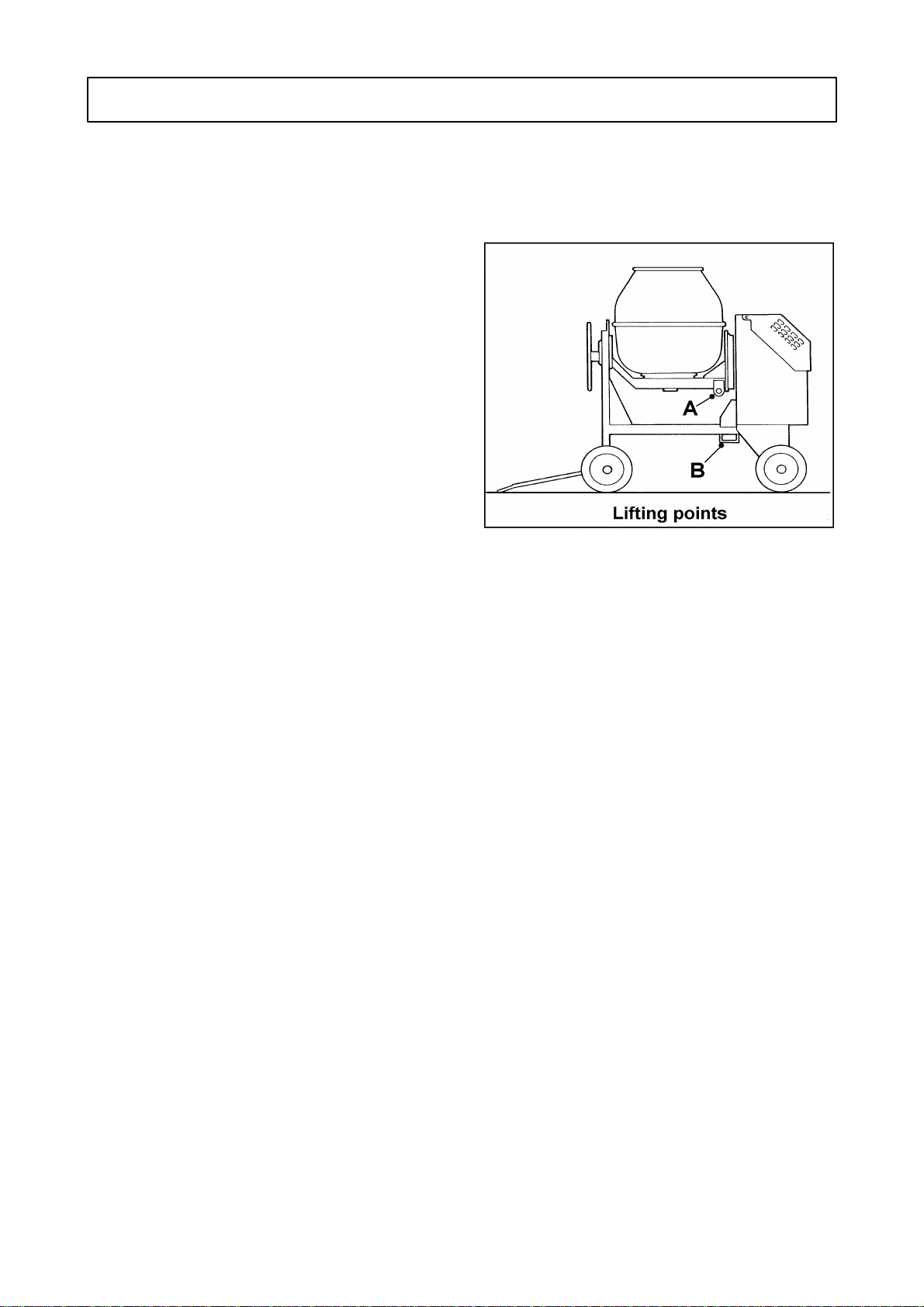
Lifting the Mixer (Crane)
Turn the drum and trunnion through
180deg. and, using the locking pin in the
tilting handwheel, lock the assembly in this
position with the lifting eye 'A' uppermost.
Attach suitable lifting equipment to the
lifting eye and slowly take the weight. Do
not 'snatch' the mixer otherwise damage
may be caused to the lifting point, trunnion
or lifting equipment. To prevent the
drawbar swinging freely as the mixer
clears the ground, rest the drawbar’s 'T'
handle on the mainframe below the
upturned drum. If the mixer is on site and
the wheels are immersed in dried
concrete or mortar the wheels must be
freed before attempts are made to lift the
mixer. Be aware that the mixer will tend to
swing as it clears the ground.
Lifting the Mixer
(Forklift/Telehandler)
Using the tilting handwheel locking
plunger, lock the drum upright as
illustrated overleaf. If the wheels are
immersed in dried concrete or mortar, free
them before attempting to lift the mixer.
Spread the fork tines and carefully
position the forks below the mainframe so
that one tine enters and passes through
the bracket 'B' below the mainframe, the
other fork should be spread as wide as
possible. Position the carriage as close as
possible to the mixer and rest the mixer’s
drawbar on one of the fork tines to prevent
it swinging freely.
Slowly tilt the carriage back slightly to
prevent the mixer rocking forward and
raise the mixer just clear of the ground.
Do not raise the mixer unnecessarily high,
keep the height to the minimum required
to clear any obstructions without unduly
obstructing your forward vision. When
travelling keep your speed to the minimum
and when loading vehicles do not raise
the mixer to the height of the bed until the
mixer is close to the vehicle. Similarly
when unloading vehicles lower the mixer
just clear of the ground as soon as it
clears the side of the vehicle.
Lashing Down
It is recommended that unless the mixer is
pulled up against a headboard or some
form of substantial wheel chocks that two
ratchet type webbing straps are used to
retain the mixer, one pulling to the rear
and one pulling to the front. The drum
should be locked in the upright position
1.6 SAFE WORKING
Lashing down & Lifting points

shown above to keep the centre of gravity
as low as possible.
Position the mixer on the vehicle bed and
chock the rear wheels to prevent it rolling
until lashed down. Turn the front axle so
that the drawbar is below the mixer and
not forming an obstruction on the vehicle
bed. Lock the drum in the upright position.
Pass one of the webbing straps between
the drum and trunnion at point 'C' and
secure the strap down to retaining hooks
on the vehicle bed in front of the mixer.
Pass the second strap between the drum
and trunnion at point 'D' and secure the
strap down to retaining hooks on the
vehicle bed to the rear of the mixer.
Tighten the straps by means of the
ratchets until the mixer is securely held.
SAFE
WORKING 1.7

1.8 SAFE WORKING

INSTALLING THE MIXER ON SITE
Welded to the mixer are lifting points.
These are provided to assist with loading
or unloading the mixer and for
transportation across site.
For mixer weights, see
"Specifications"
Never carry mixers by their lifting points
on public roads.
Do not tow four wheeled mixers across
uneven ground.
The ground on which the mixer stands
must be level and stable. Ensure that the
wheels are chocked.
Electrically driven mixers:
Always ensure that the power supply is
correctly connected or disconnected by
a qualified electrician.
Electrical cables must be of a suitably
armoured type. Ensure that they are
protected from damage and are not
liable to be tripped over.
Do not connect to a household socket!
Use only with an RCD protected
supply. Only connect via special
feeding point (e.g. power distribution
panel on building site with fault-current-
breaker).
ENGINE OPERATION
As soon as the engine has
started the mixing drum will
begin to rotate.
Before starting the engine:
Ensure the engine is free to turn without
obstruction.
Check that the lubricating oil level is
correct. The oil sump must be filled to the
‘full’ mark on the dipstick; do not overfill.
Check that the fuel supply is adequate
and the system is primed.
Electric key start machines only:
Ensure that the battery is connected,
fully charged and serviceable.
ENGINE SAFETY
The following pages of
engine operating instructions
are of a general nature and
should be read in
conjunction with, or
substituted by the engine
manufacturers instructions.
Starting any diesel engine
can be dangerous in the
hands of inexperienced
people.
Before attempting to start
any engine the operator
should read the 'Safe
Working' section of this book
and be conversant with the
use of the engine controls
and the correct starting
procedures.
ETHER BASED COLD START
AIDS IN AEROSOL CANS
MUST NOT BE USED UNDER
ANY CIRCUMSTANCES.
EXHAUST GASES CONTAIN
CARBON MONOXIDE WHICH
IS A COLOURLESS,
ODOURLESS AND
POISONOUS GAS THAT CAN
CAUSE UNCONSCIOUSNESS
AND DEATH.
OPERATION 2.1

LT/LV1 engine
Description
A Dipstick
BLubricating oil filler
CEngine control
DDecompressor lever
EAir cleaner
FFuel tank
The cold start aid (where fitted)
The cold start aid is fitted to the
combustion air intake port and is used
when the ambient temperature is below
–10 deg.C (14 deg.F).
With the fuel turned on, turn the engine
for up to 20 revolutions to prime the
fuel and lubrication systems.
Withdraw the plunger (A) and fill one
third of the cup (B) with the same type
of lubricating oil as used in the engine
Replace the plunger and inject the oil just
before starting the engine
The device must not be used
more than three times in
succession during the same
attempt to start the engine.
The starting handle(s)
A non-limited kick-back handle (C) or
limited kick-back handle (D) system may
be fitted to the engine.
The two handles are not interchangeable
and care must be taken to ensure the
correct type is retained with the engine.
Always use the correct starting handle
which has been designed for the engine.
2.2 OPERATION

Ensure there are no burrs on the handle.
Before attempting to use the handle, clean
and lightly oil that part of it which fits onto
the engine.
Hand starting the engine
Select the excess fuel position by gently
pulling the engine control lever (L)
outward over the middle catch (M) and
turning it fully clockwise.
Move the decompressor lever towards the
flywheel (N).
Insert the correct handle (See: 'Starting
handles) into the starting housing.
Turn the engine slowly for up to 20 turns
to prime the combustion chamber and
lubricating oil system.
Maintaining a firm grip on the starting
handle, crank the engine really fast and
when sufficient speed is obtained move
the decompressor lever towards the gear
end and continue to crank until the engine
fires.
Retain a firm grip on the handle and
remove it from the engine.
Close the engine lid and ensure that it
stays closed while the engine is running.
Do not stop the engine with a
load in the drum.
.
Stopping the engine
Turn the engine control anti-clockwise to
the STOP position and hold it there until
the engine comes to rest.
Never stop the engine by
using the decompressor
lever, or valve damage may
occur.
OPERATION 2.3

AC1-05 engine
(Electric start with key)
Description
AOil filler
BEngine control
CAir cleaner
DFuel tank
EKey switch
FDipstick
Starting the engine
Pull the lever (B) towards you. This will
move the engine control anti-clockwise
into the RUN position.
Turn the start key clockwise (G) and
release immediately the engine fires.
Do not operate the start key for more than
20 seconds at a time.
Close the engine lid and ensure that it
stays closed while the engine is running.
Do not stop the engine with a
load in the drum.
Stopping the engine
Push lever (B) forwards to move the
engine control to the STOP position, then
wait until the engine comes to rest.
After the engine has stopped ensure the
electric start key is switched off.
Never stop the engine by
using the decompressor
lever, or valve damage may
occur.
2.4 OPERATION

Yanmar L40/L48
Description
AFuel cock
BEngine speed lever
E Starting key
Electric starting the engine
Open the fuel cock (A). Put the engine
start lever to the RUN position (B).
Turn the starting key (E) clockwise to
START position.
Remove your hand from the key as soon
as the engine starts.
If the engine does not start after 10
seconds, wait a while (for about 15
seconds) before attempting to start again.
If the starting motor is turned
for too long, the battery will
go flat and motor seizure will
occur. Always leave the
starting key turned on, in the
ON position, while the engine
is running.
Check monthly that the
battery fluid is at the correct
level.
Cold Starting
In cold weather, if the engine is hard to
start, remove the rubber plug of the rocker
arm cover and add 2cc of engine oil
before starting. Do not add more than 2cc
of engine oil to prevent internal engine
damage.
Never use any cold starting
aids such as ether (Easy
start), gasoline, paint ether or
other volatile liquid or gas.
Keep the rubber plug in the
cover except when adding oil.
1
If the plug is not in place, rain,
dirt and other contaminants
may enter the engine and
cause accelerated wear of
internal parts.
OPERATION 2.5

Yanmar L40/L48
Stopping the engine
Before stopping the engine, move the
engine speed lever to SLOW speed, and
run the engine for about 3 minutes with no
load.
Return the engine speed lever to the
STOP position.
With electric-start engines, turn the starter
key to the OFF position.
Set the fuel cock lever to the CLOSED
position.
Slowly pull out the recoil handle until
pressure is felt (that is, to the point in the
compression stroke where the intake and
exhaust valves are closed), and leave the
handle in this position. This prevents rust
from forming while the engine is not in
use.
If the engine keeps on running
even after the speed lever is
placed at STOP position, stop
the engine by closing the fuel
cock.
When stopping the engine,
reduce the load slowly. Do not
stop the engine suddenly since
it may cause the temperature
to rise abnormally.
Do not stop the engine with the
decompression lever.
2.6 OPERATION

Yanmar L40/L48
Manual starting in the event of a flat
battery
Description
AFuel cock
B Engine speed lever
CDecompression lever
DRecoil starting handle
Starting the engine
Open the fuel cock (A).
Put the engine start lever to the RUN
position (B).
Turn the start key to ON.
Pull out the recoil starting handle (D)
slowly until you feel a strong resistance,
then return it to the initial position.
Push down the decompression lever (C).
It will return automatically when the recoil
starter is pulled.
Grip the recoil starting handle (D) firmly
with both hands. Pull the rope hard and
fast. Pull it all the way out.
The engine should now have started. If it
has not, repeat the procedure.
Cold Starting
In cold weather, if the engine is hard to
start, use the same cold start procedure
as described on page 2.5.
OPERATION 2.7

Honda
The following engine operating
instructions should be read in conjunction
with the Honda Owner’s Manual.
Starting the engine
Turn the fuel valve to the ON position.
Move the choke lever to the CLOSED
position.
Do not use the choke if the engine is
warm or the air temperature is high.
Turn the engine switch to the ON position.
Pull the starter grip lighty until resistance
is felt, then pull briskly.
Do not allow the starter grip to snap back.
Return it gently to prevent damage to the
starter.
Note: There is no throttle adjustment. The
engine speed is set at the factory
and there should be no attempt to
change it.
2.8 OPERATION
Other manuals for 100T
4
This manual suits for next models
2
Table of contents
Other Winget Mixer manuals

Winget
Winget 200T Instruction manual

Winget
Winget 200T Service manual

Winget
Winget Croker CUMFLOW RP100XD User manual

Winget
Winget 200TM Instruction manual

Winget
Winget 500R Instruction manual

Winget
Winget CUMFLOW RP150XD MK2 User manual

Winget
Winget Crocker RP1500XD User manual

Winget
Winget CUMFLOW RP100XD MK2 User manual

Winget
Winget 200T User manual

Winget
Winget 100T Instruction manual