wink haus blueSmart ETB-IM User manual

Operating manual
blueSmart electronic door handle for internal doors (ETB-IM)

Aug. Winkhaus GmbH & Co. KG ∙ Hessenweg 9 ∙ 48157 Münster ∙ T +49 251 4908 - 0 ∙ zutrittsorganisation@winkhaus.de ∙ www.winkhaus.de
ETB-IM 2
Operating manual
Table of contents
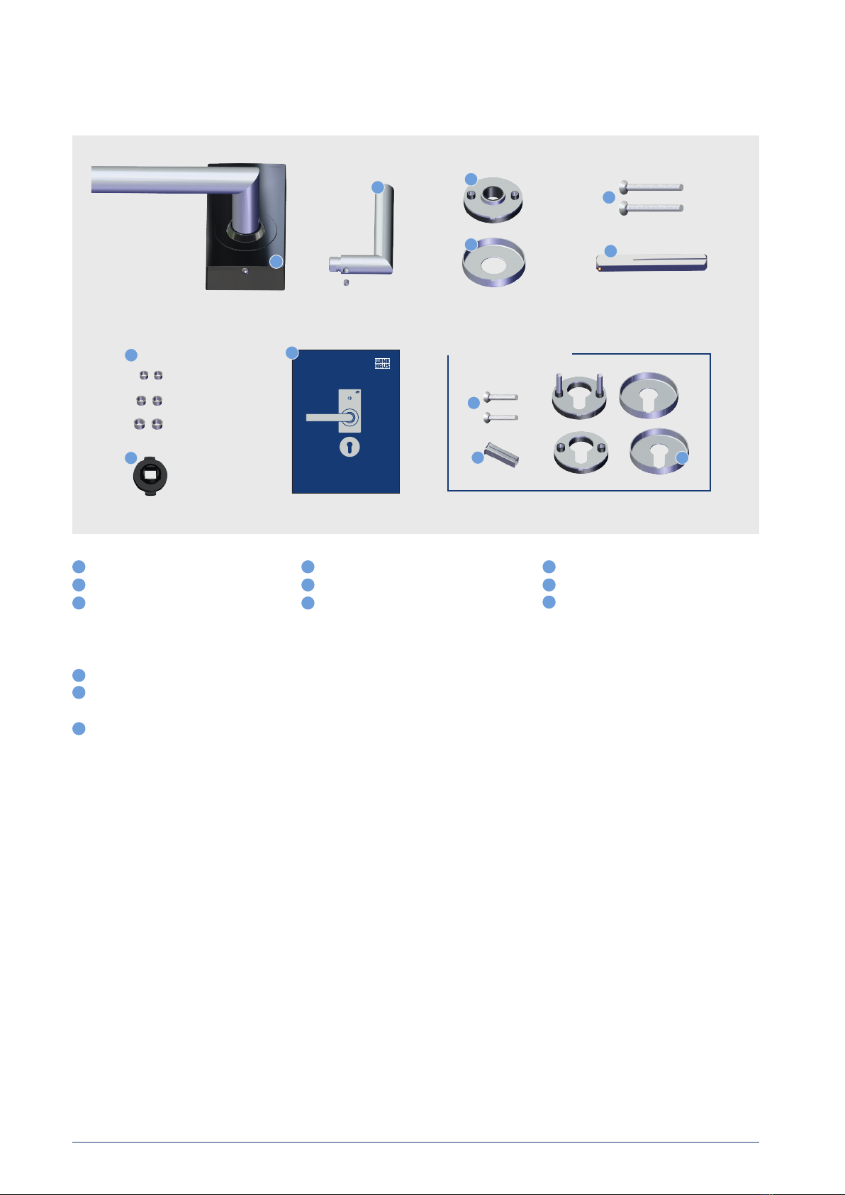
1 Included in delivery............................................................................................................................................................................................................................ 3
2 Product overview................................................................................................................................................................................................................................4
3 Security..................................................................................................................................................................................................................................................... 5
3.1 Intended use ............................................................................................................................................................................................................................... 5
3.2 Safety information and liability exclusions ................................................................................................................................................................ 5
4 Transport and storage......................................................................................................................................................................................................................6
4.1 Transport and unpacking ....................................................................................................................................................................................................6
4.2 Storage without batteries ...................................................................................................................................................................................................6
4.3 Storage with batteries........................................................................................................................................................................................................... 6
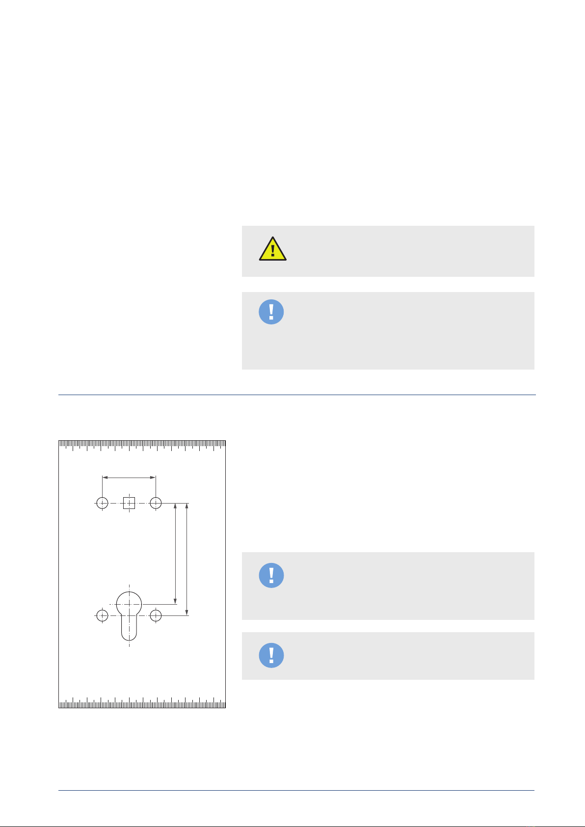
5 Assembly preparation ...................................................................................................................................................................................................................... 7
5.1 Definition of terms................................................................................................................................................................................................................... 7
5.2 Tools ................................................................................................................................................................................................................................................ 7
5.3 Door thickness tolerance table ........................................................................................................................................................................................ 8
5.4 Integrating the product in a blueSmart locking system .................................................................................................................................... 9
5.5 Dismantling the old door fitting....................................................................................................................................................................................... 8
5.6 Dismantling the lock and door handle .........................................................................................................................................................................9
6 Mounting instructions..................................................................................................................................................................................................................... 10
7 Mounting ................................................................................................................................................................................................................................................ 10
8 Functional testing ..............................................................................................................................................................................................................................13
9 Operation............................................................................................................................................................................................................................................... 14
9.1 Identification media.............................................................................................................................................................................................................. 14
9.2 Individual release.................................................................................................................................................................................................................... 14
9.3 Manual permanent release (DFG) .................................................................................................................................................................................15
9.4 Release time.............................................................................................................................................................................................................................. 16
9.5 Permanent release modes ................................................................................................................................................................................................ 16
9.6 Saving of locking events .................................................................................................................................................................................................... 16
9.7 Battery warning messages................................................................................................................................................................................................17
10 Converting from handle left to handle right ...................................................................................................................................................................... 18
11 Cleaning and maintenance .........................................................................................................................................................................................................20
11.1 Cleaning the electronic door fitting ........................................................................................................................................................................... 20
11.2 Replacing the battery.........................................................................................................................................................................................................20
11.3 Carrying out a firmware update ................................................................................................................................................................................... 22
12 Troubleshooting................................................................................................................................................................................................................................ 23
13 Spare parts and accessories...................................................................................................................................................................................................... 24
14 Disassembly .........................................................................................................................................................................................................................................25
15 Disposal instructions for product and packaging ......................................................................................................................................................... 26
16 Technical specifications................................................................................................................................................................................................................ 26

bluecompact.com
Aug. Winkhaus GmbH & Co. KG
Hessenweg 9
48157 Münster
Deutschland
Telefon: +49 0251 4908-0
Telefax: +49 0251 4908-145
Internet: www.winkhaus.com
Quick Installation Guide
ETB-IM
OPTIONAL
Ø 8 mm
Ø 9 mm
Ø 10 mm
8
7
12119
10
Aug. Winkhaus GmbH & Co. KG ∙ Hessenweg 9 ∙ 48157 Münster ∙ T +49 251 4908 - 0 ∙ zutrittsorganisation@winkhaus.de ∙ www.winkhaus.de
ETB-IM 3
Operating manual
1 Included in delivery
Electronic door fitting A-side
Handle for B-side
Base rosette for B-side
2x M5 screws for optional rosette pair
Reducing sleeve for 7 mm and
8.5 mm handle B-side
Rosette pair for profile cylinder hole
(with/without profile cylinder)
Cover rosette for B-side
2 x M5 screws
Spindle
Adjustment sleeve set
Installation manual
Mounting aid (only with 8 mm and
9 mm handles)
1 4 7
82 5
3 6
Optional
1
23
4
5
6
10
11
12
9

Aug. Winkhaus GmbH & Co. KG ∙ Hessenweg 9 ∙ 48157 Münster ∙ T +49 251 4908 - 0 ∙ zutrittsorganisation@winkhaus.de ∙ www.winkhaus.de
ETB-IM 4
Operating manual
2 Product overview
Electronic door fitting A-side incl. pre-assembled cover, handle A-side,
inserted batteries and adhesive pad on the rear
Handle and base rosette and cover rosette for B-side
2 x M5 screws in length suitable for the door thickness for screwing via
rosette holes
Spindle in the ordered thickness and length suitable for the door thickness
Adjustment sleeve set with 2 sleeves each for hole diameters 8, 9 and
10 mm for optimal positive screw connection of the electronic fitting
(rotation lock)
Optional: 2 x M5 screws in a suitable length for the specified door
thickness for optional profile cylinder rosettes
Optional: Rosette pair for profile cylinder hole (with/without profile
cylinder)
With 8 mm and 9 mm handle: Assembly assistance for assembly
Optional:
With a 8.5 mm handle:
- reducing sleeve handle B-side from 9 mm to 8.5 mm spindle
With a 7 mm handle:
- reducing sleeve handle B-side from 8 mm to 7 mm spindle
1
2
3
5
6
7
9
2
2
4
1
2
3
4
5
6
7
9
8
AB
Note!
There are details (in the manual) that are also impor-
tant for the user. Please hand over the manual to the
user after installation is completed.
8

Aug. Winkhaus GmbH & Co. KG ∙ Hessenweg 9 ∙ 48157 Münster ∙ T +49 251 4908 - 0 ∙ zutrittsorganisation@winkhaus.de ∙ www.winkhaus.de
ETB-IM 5
Operating manual
3 Safety
3.1 Intended use This product is an electronic door fitting from the Winkhaus blueSmart
product range. Authentication takes place by presenting an authorised
identification medium and enables the door to be opened when the door
handle is actuated on the A-side. The authorisations are managed with the
blueSmart management software blueControl. The product may only be
used for opening and closing doors in interior areas in accordance with the
technical specification (see 16 Technical data). No other use is permitted.
• Batteries can pose a risk of fire, burns or chemical burns when used
incorrectly. Batteries should therefore not be charged, manipulated,
short-circuited or burnt.
• The electronic door handle may only be operated with three batteries of
the same type. For safety reasons (CE approval), the batteries from the
Winkhaus spare battery set (Panasonic LR03, AAA) must be used.
If lithium batteries are used as an alternative, type FR03, AAA from
Energizer is approved.
• Do not use force to press batteries into the battery compartment.
• Note the polarity of the batteries.
• Incorrectly programmed products can prevent access to a room.
No liability will be accepted for issues such as prevented access to injured
or endangered persons and associated property damage and personal
injury.
• For securing doors, the simultaneous use of a profile cylinder in the door
lock is recommended to enable access at any time.
• The product may only be used for opening and closing doors in interior
areas. No other use is permitted.
• Assembly, programming and disassembly may only be carried out by
specialist personnel.
• No liability will be accepted for damage caused by incorrect assembly
and/or installation.
• Drilling is carried out at your own risk. No liability will be accepted for any
resulting damage to door sashes or the lock, as well as any other parts.
• Do not touch electronic components.
• Do not oil or grease the electronic door fitting and its individual
components, do not treat them with graphite, do not bring them into
contact with paints, thinners, acids or alcohol or cleaning agents
containing alcohol or disinfectants.
• Do not store within reach of children.
• The electronic door fitting only acts on the latch of the mortice lock
(exception: handle-actuated shootbolt lock, self-locking panic lock).
• If a door must be locked in accordance with insurance regulations,
a self-locking panic lock (SVP lock) must be used. We recommend also
using a locking cylinder.
• When replacing door fittings for the Winkhaus electronic door fitting,
the specifications of the standards, EN 179, for example, must be
complied with. The ETB-IM may not be installed in doors in accordance
with EN1125.
3.2 Safety information and liability
exclusions

Aug. Winkhaus GmbH & Co. KG ∙ Hessenweg 9 ∙ 48157 Münster ∙ T +49 251 4908 - 0 ∙ zutrittsorganisation@winkhaus.de ∙ www.winkhaus.de
ETB-IM 6
Operating manual
• Screws may only be tightened by hand. If the screws are tightened too
tightly, the function of the lock and handle springs may be impaired and
the door sash may be damaged.
• We reserve the right to implement changes or technical developments
without notice.
• Documentation is created to the best of our knowledge and with the
utmost care. Errors cannot be ruled out. No liability will be accepted for
errors.
• In the event of deviations between content in foreign language versions,
the German original shall apply in case of doubt.
Electronic door handles are packaged securely for dry transport. They will
only function correctly if the packaging is undamaged.
1. Check the packaging for damage.
2. Inform Winkhaus Customer Service immediately of any damage.
3. Check to ensure supply is complete.
4. Close packaging and leave contents in the packaging until
installation or use.
For prolonged storage periods, remove the batteries from the electronic
door handle to safeguard against battery leakage (see 11.2 Replacing the
battery). The electronic door handle can be stored without batteries in a
drawer or cabinet at room temperature.
The storage location of the batteries and components with batteries must
fulfil the following conditions:
• Storage in interior areas at temperatures of +5°C to +30°C.
• Air humidity maximum 70%.
• Protection from moisture, in particular condensation.
• Protection against heat.
• Protection against vibration.
• Do not allow components of leaking batteries to enter the environment
(see 15 Disposal)!
• Protection against access by unauthorised persons.
4.1 Transport and unpacking
4.2 Storage without batteries
4.3 Storage with batteries
Note:
Damage to batteries due to incorrect storage location!
Environmental protection:
Damage to the environment due to leaking battery
fluid.
4 Transport and storage

Aug. Winkhaus GmbH & Co. KG ∙ Hessenweg 9 ∙ 48157 Münster ∙ T +49 251 4908 - 0 ∙ zutrittsorganisation@winkhaus.de ∙ www.winkhaus.de
ETB-IM 7
Operating manual
The tools shown in the figure on the left are required for assembly:
• Screwdriver PH1 (magnetized where applicable).
• Screwdriver PH2.
• Allen key size 3.
• Where applicable: Electric drill and borer.
• Drill template for door fittings, the drill template from the Quick Installation
Guide may be used as an alternative if the dimensions are suitable.
The following are also required for disassembling the existing door fitting
(see 14 Disassembly) (optionally available):
• Cover lifter (Art. no. 492 935 3).
• Circlip pliers form B in accordance with DIN 5254 (Art. no. 507 446 0).
In order to avoid damage to the electronic door handle, the door and the
lock during assembly, only screws and spindles suitable for the door sash
thickness included in delivery may be used.
5 Assembly preparation
5.1 Definition of terms
5.2 Tools
1
2
3
4
5
6
Spindle dimension
Backset
72
80
Lock follower
Latch
Deadbolt
Face plate screw
Faceplate
Cylinder
Drill hole for the fitting
1 4 7
2 5
3 6
7
38

Aug. Winkhaus GmbH & Co. KG ∙ Hessenweg 9 ∙ 48157 Münster ∙ T +49 251 4908 - 0 ∙ zutrittsorganisation@winkhaus.de ∙ www.winkhaus.de
ETB-IM 8
Operating manual
5.3 Door thickness tolerance table
Possible door thick-
nesses
Length of screws electronic handle
(Lock follower area)
Length of screws profile cylinder cover
(Countersunk screw)
Door thickness order
40 mm, 45 mm >36 – 45 mm 55 mm (Art. no. 507 136 6) 35 mm (Art. no. 507 136 4)
50 mm, 55 mm >45 – 55 mm 65 mm (Art. no. 507 136 7) 45 mm (Art. no. 507 136 5)
60 mm, 65 mm >55 – 65 mm 75 mm (Art. no. 507 136 8) 55 mm (Art. no. 507 136 6)
70 mm, 75 mm >65 – 75 mm 85 mm (Art. no. 507 136 9) 65 mm (Art. no. 507 136 7)
80 mm, 85 mm >75 – 85 mm 95 mm (Art. no. 507 137 0) 75 mm (Art. no. 507 136 8)
90 mm, 95 mm >85 – 95 mm 105 mm (Art. no. 507 137 1) 85 mm (Art. no. 507 136 9)
100 mm, 105 mm >95 – 105 mm 115 mm (Art. no. 507 137 2) 95 mm (Art. no. 507 137 0)
110 mm, 115 mm >105 – 115 mm 125 mm (Art. no. 507 137 3) 105 mm (Art. no. 507 137 1)
120 mm, 125 mm >115 – 125 mm 135 mm (Art. no. 507 137 4) 115 mm (Art. no. 507 137 2)
If the electronic door handle has to be mounted on a dierent door, this is
possible within tight tolerances with the screws and square pins provided.
If a conversion is required outside of this tolerance table, always use
Winkhaus genuine spare parts (spindle and self-locking screws in the
relevant lengths) to maintain the warranty.
Possible door thick-
nesses
Length of
spindle
Spindle ■7.0
(Art. no.)
Spindle ■8.0
(Art. no.)
Spindle ■8.5
(Art. no.)
Spindle ■9.0
(Art. no.)
Door thickness order
40 mm, 45 mm >36 – 45 mm 70 mm 507 439 3 507 441 6 507 442 5 507 443 5
50 mm, 55 mm >45 – 55 mm 80 mm 507 440 8 507 441 7 507 442 6 507 443 6
60 mm, 65 mm >55 – 65 mm 90 mm 507 440 9 507 441 8 507 442 8 507 443 7
70 mm, 75 mm >65 – 75 mm 100 mm 507 441 0 507 441 9 507 442 9 507 443 8
80 mm, 85 mm >75 – 85 mm 110 mm 507 441 1 507 442 0 507 443 0 507 443 9
90 mm, 95 mm >85 – 95 mm 120 mm 507 441 2 507 442 1 507 443 1 507 444 0
100 mm, 105 mm >95 – 105 mm 130 mm 507 441 3 507 442 2 507 443 2 507 444 1
110 mm, 115 mm >105 – 115 mm 140 mm 507 441 4 507 442 3 507 443 3 507 444 2
120 mm, 125 mm >115 – 125 mm 150 mm 507 441 5 507 442 4 507 443 4 507 444 3

Tip:
Use the drill template provided to mark the necessary drill holes before
dismantling. Drill the door sides separately.
Aug. Winkhaus GmbH & Co. KG ∙ Hessenweg 9 ∙ 48157 Münster ∙ T +49 251 4908 - 0 ∙ zutrittsorganisation@winkhaus.de ∙ www.winkhaus.de
ETB-IM 9
Operating manual
5.5 Dismantling the old door fitting Step 1: Release the existing door fitting from the door sash where
necessary. For this, follow the manufacturer instructions for the
existing door fitting (see 14 Disassembly).
Step 2: Remove any handle pins from the lock follower by shaking gently
and pulling.
Note:
Do not use force, as the lock and/or the door sash could
be damaged.
5.6 Dismantling the lock and door handle
Note!
The profile cylinder (1) and lock (2) must be removed
from the door before drilling.
Note!
To avoid damage to the door sash, we recommend us-
ing a rosette lifter and a protective plate (not included
in delivery).
1
2
5.4 Integrating the product in a
blueSmart locking system
As with other components, the integration of the electronic door handle in
the locking system takes place via a programming device or database import
into the blueControl database of your Winkhaus locking system. The
function programming that takes place within the blueControl management
software in accordance with the relevant documentation, is applied in the
electronic door handle by the usual means.
Transactions are transferred with the programming device type BCP-NG or
BXP BS. Alternatively, the blueSmart Active (bSA) key can be used. In
addition to the programming device and active key, the commands are also
transferred via the Winkhaus virtual network.

4
70
60 50 40
30 20 10 0 10 20 30 40 50 60
70
70
60 50 40
30 20 10 0 10 20 30 40 50 60
70
80
72
Germany - DIN 18251-1
38
https://www.winkhaus.com/downloads
https://www.youtube.com
„Winkhaus blueSmart ETB-IM“
Aug. Winkhaus GmbH & Co. KG ∙ Hessenweg 9 ∙ 48157 Münster ∙ T +49 251 4908 - 0 ∙ zutrittsorganisation@winkhaus.de ∙ www.winkhaus.de
ETB-IM 10
Operating manual
Step 1: Door preparation: Ensure that Ø 8 mm drill holes are present on the
right and left of the lock follower (optional and only in the area of
the follower: Ø 9 mm or 10 mm) at a distance of 38 mm from centre
of hole to centre of hole (see 5.1 Definition of terms). Proceed in the
same way if the optional profile cylinder rosettes have been
ordered. Use a spirit level and the drill template from the Quick
Installation Guide.
Note!
The drill holes in your door in the lock follower area
or the profile cylinder hole often require reworking in
preparation for the ETB-IM assembly.
Note!
Illustration not to scale!
7 Installation
6 Mounting instructions • Batteries are already inserted.
• Keep low-frequency and magnetic interfering sources, such as
powerpacks, away.
• Do not subject the electronic door handle to mechanical stresses (knocks,
shaking etc.) during assembly.
• Mount evenly on the door without tension or bends.
• If necessary, use the drill template provided for drilling.
• Only use the mounting material provided.
• To prevent the door handle or its individual parts from shaking loose, sti,
self-locking screws with suitable coating are used, which could make the
assembly more dicult.
Warning!
The assembly may only be carried out by qualified
personnel.
Note:
- The screws may only be tightened by hand. Do NOT
use a cordless screwdriver to tighten the screws!
- No liability will be accepted for destruction due to the
screws being tightened too tightly!

Step 3
Step 4
Step 5
Step 6
Aug. Winkhaus GmbH & Co. KG ∙ Hessenweg 9 ∙ 48157 Münster ∙ T +49 251 4908 - 0 ∙ zutrittsorganisation@winkhaus.de ∙ www.winkhaus.de
ETB-IM 11
Operating manual
Step 2: Insert the lock and the profile cylinder in the door again.
Step 3: Place the adjustment sleeves in the drill holes next to the lock
follower. For Ø10 mm drill holes use the large, with Ø9mm holes
use the medium and with Ø 8 mm drill holes use the small
adjustment sleeves.
Step 4: Remove the electronic door handle from the box and turn the
coupling on the rear of the electronic door fitting into the correct
position.
Step 5: Take the spindle and push it into the coupling of the electronic door
handle on the back until the pressure fitting engages audibly and
tangibly.
Then remove the battery contact strips.
Step 6: Feed the spindle, including the electronic door fitting, in through
the lock follower from the A-side until the electronic door fitting is
touching the door sash.
Note!
The adjustment sleeves are essential for rotation
locking! Do not carry out the assembly without adjust-
ment sleeves! For doors that need an additional torsion
protection the door fitting can be screwed with the door
sash by means of the two upper holes beneath the cover.
Note!
The spindle must be designed so that the gap for the
grub screw points to the deadbolt and the door latch.
Note!
The electronic door fitting can only be mounted if the
spindle has been measured correctly.

Step 9 (Illustration A)
Step 9 (Illustration B)
Step 7
Step 8
Aug. Winkhaus GmbH & Co. KG ∙ Hessenweg 9 ∙ 48157 Münster ∙ T +49 251 4908 - 0 ∙ zutrittsorganisation@winkhaus.de ∙ www.winkhaus.de
ETB-IM 12
Operating manual
Step 7: Take the base rosette for the B-side, push it around correctly (gap
for the cover rosette points downwards) on the spindle and guide it
through the drill holes in the door sash towards the door sash to the
stop. With a 8mm and 9mm spindle, guide the assembly assistance
included in the latch onto the spindle as shown, so that the flush-
mounting side points outwards and the gaps are pointing up and
down. Press the assembly assistance firmly into the base rosette.
Screw the base rosette with the door fitting with the M5 screws and
a screwdriver (PH2).
With 8 mm and 9 mm square pins, remove the assembly assistance
from the base rosette.
Step 8: Press the cover rosette onto the base rosette until it engages
audibly and tangibly.
Step 9: Take the handle for the B-side. With a 7 mm or 8.5 mm spindle,
insert the reducing sleeve provided into the door handle and push
it (with the optional sleeve) onto the spindle on the B-side
(Illustration A). Push on the handle until it engages audibly and
tangibly (Illustration B).
Note!
If profile cylinder rosettes have been ordered, use the
longer screws for the electronic door fitting. The screw
lock coating means that higher force is required to
screw in the screws. Do not overtighten the screws.
Ensure that the lock and the door sash do not brace
due to the screws being tightened too tightly.

Step 10
8 Functional testing
Functional testing
Aug. Winkhaus GmbH & Co. KG ∙ Hessenweg 9 ∙ 48157 Münster ∙ T +49 251 4908 - 0 ∙ zutrittsorganisation@winkhaus.de ∙ www.winkhaus.de
ETB-IM 13
Operating manual
Step 10: Screw the handle with the spindle with the grub screw using the
Allen key (size 3).
Step 11: Set the time for the electronics using the programming device and
the adapter cable A5 (see Operating manual programming device).
Then carry out a function test using authorised identification media
with the door open (see 8 Functional testing).
Step 12: Where applicable, mount the profile cylinder cover rosettes with
the corresponding M5 screws.
• Set the time via the programming device and the adapter cable type A5
(round programming adapter). A valid time is signalled (see
12Troubleshooting).
• Hold the identification medium against the interaction surface as shown.
• A brief signal tone sounds when access is authorised. The door handle is
engaged for about 3 seconds. The door can be opened.
• A longer signal tone sounds when access is not authorised. The door
handle remains in neutral position.
• Activate permanent release by presenting the identification medium for
approx. 3-5 seconds. The LED lights up green twice and 2 short signal
tones sound at the same time. The door handle is engaged permanently
(until the next auto o where applicable). The door is then permanently
accessible.
• Deactivate the permanent release by presenting the identification medium
for approx. 3-5 seconds. The LED lights up green twice, 2 long signal tones
sound at the same time and the permanent release is reset. The door
handle returns to neutral position.
• The system and/or door can be commissioned once all functions have
been tested.
Warning!
The time on the electronics must be set before carrying
out the functional test. See the manual for the pro-
gramming device for more information. The functions
may only be tested while the door is open. The door
can be opened at any time with the handle on the
B-side. The handle on the A-side is in neutral position.

Aug. Winkhaus GmbH & Co. KG ∙ Hessenweg 9 ∙ 48157 Münster ∙ T +49 251 4908 - 0 ∙ zutrittsorganisation@winkhaus.de ∙ www.winkhaus.de
ETB-IM 14
Operating manual
Present the identification medium slowly and hold it in front of the interaction
surface marked with coloured semicircular crescents until authorisation is
complete, which is confirmed with a green LED and an acoustic signal.
All signals are always output following actuation with an identification
medium belonging to the system. No signals are given with keys that do not
belong to the system.
Presentation of authorised identification medium
Signal duration 500 ms green LED and 200 ms acoustic signal, after the
authorisation check and after the release position is reached (not in the
permanent release state). The end of the release is not signalled. The
actuators noticeably move back.
Activation of the actuators for engaging the handle. The actuators are
disengaged once the release time has expired.
Presentation of unauthorised identification medium belonging to the
system
Signal duration 750 ms (red LED and acoustic signal), after the authorisation
check (not in the permanent release state).
Actuator disengages if no permanent release is set up, regardless of the
current position. Switched on permanent release remains in place.
9.2 Individual release
9 Operation
9.1 Identification media The electronic door handle can be actuated with all authorised identification
media belonging to the system (user key, premium key, user key with
additional transponder, active key, key fob TAG, cards and mechatronic
keys).

Aug. Winkhaus GmbH & Co. KG ∙ Hessenweg 9 ∙ 48157 Münster ∙ T +49 251 4908 - 0 ∙ zutrittsorganisation@winkhaus.de ∙ www.winkhaus.de
ETB-IM 15
Operating manual
9.3 Manual permanent release (DFG) The use of the permanent release (DFG) requires prior parametrisation of
the electronic door handle and locking authorisations for identification
media to be set up (permanent release authorisation) (see 9.5 Permanent
release modes).
Key was read in permanent release mode
Signal duration 12.5ms, after the key has been read successfully, regardless
of the result of the authorisation check (only in “permanent release” state).
No actuator activation. Switched on permanent release remains in place.
Manual switch-on of the permanent release: Switch on the permanent
release by presenting the identification medium for approx. 3-5 seconds
500ms signal green LED, after 300ms acoustic signal, buzzer for 200ms.
80 ms pause, simultaneous LED (500 ms) and buzzer (200 ms). For the
activation of the permanent release, the identification medium must be
authorised and have the permanent release function on the electronic door
handle. Present the identification medium in the centre in front of the
interaction surface. The second signal is only output if the actuator has
engaged the handle and the switch was noted in the system data. With
automatic permanent release switching, this signal is not output.
2 short signal tones sound and the door handle is permanently engaged. The
door is then permanently accessible.
Manual switch-o of the permanent release: Switch o the permanent
release by presenting the identification medium for approx. 3-5 seconds
750ms signal (green LED and acoustic), 80ms pause, 750ms signal (green
LED and acoustic). For the deactivation of the permanent release, the key
must be authorised and have the permanent release function on the
electronic door handle. Present the identification medium in the centre in
front of the interaction surface. The second signal is only output if the
actuator has disengaged the handle and the switch was noted in the system
data. With automatic permanent release switching, this signal is not output.
2 long signal tones sound and the permanent release is reset. The door
handle returns to neutral position.
Note!
A manually set permanent release can be switched o
again manually. At the time of the switch, the identifica-
tion medium must be authorised at the location (on the
ETB-IM) and at the time (at the time of switching). The
permanent release can also be switched o automati-
cally (see 9.5 Permanent release modes).

Aug. Winkhaus GmbH & Co. KG ∙ Hessenweg 9 ∙ 48157 Münster ∙ T +49 251 4908 - 0 ∙ zutrittsorganisation@winkhaus.de ∙ www.winkhaus.de
ETB-IM 16
Operating manual
9.6 Saving of locking events
The preset release time set at the factory is 3 seconds. This can be modified
via the blueControl software and programmed in the component via the
programming device BCP-NG or BXP BS, the blueSmart Active key or via
the optional Winkhaus virtual network.
One permanent release mode per electronic door handle can be
parametrised via the management software.
The electronic door handle supports all permanent release modes that can
be set in the blueControl management software:
• OFF: no permanent release can be set.
• Manual: Can only be switched on and o manually.
• Auto ON / Auto OFF - no manual intervention: The permanent release can
not be switched on and o manually. The switch-on and switch-o always
takes place according to the specified values.
• Auto ON / Auto OFF - manual intervention within time profile: Permanent
release switches on and o automatically according to the specified
values. Manual override until the next switching via authorised
identification medium within the time profile.
• Auto ON / Auto OFF - unlimited manual intervention: Permanent release
switches on and o automatically according to the specified values.
Manual override until the next switching via authorised identification
medium regardless of the key time profile.
• Auto ON / Auto OFF - manual intervention within time profile: Permanent
release is only switched on manually. Permanent release can be
deactivated within the time profile. Automatic switch-o takes place at
the Auto OFF switching time.
• Auto ON / Auto OFF - unlimited manual intervention: Regardless of the
key time profile, permanent release can be switched on and o at any
time. Automatic switch-o takes place at the Auto OFF switching time.
• Manual ON / Auto OFF relative: Permanent release is only switched on
manually. Permanent release can be deactivated within the time profile.
Automatic switch-o takes place at the relative Auto OFF switching time
(e.g. 60 minutes since permanent release was switched on).
For programming the ETB-IM the blueControl Professional from version
4.6.2.0 or the blueControl Start / blueControl Start virtual from version 5.7 is
required.
Authorised and unauthorised access attempts with identification media
belonging to the system are logged in the event memory with the date, time
and the number of the identification medium. The electronic door fitting has
a ring memory, which logs the last 2,000 locking events. The settings for the
logging function and/or the event transport via the optional Winkhaus
virtual network can be managed via the blueControl software.
9.5 Permanent release modes
9.4 Release time

Aug. Winkhaus GmbH & Co. KG ∙ Hessenweg 9 ∙ 48157 Münster ∙ T +49 251 4908 - 0 ∙ zutrittsorganisation@winkhaus.de ∙ www.winkhaus.de
ETB-IM 17
Operating manual
9.7 Battery warning messages
Note!
Once the battery has drained completely, the electronic
door fitting may only be actuated again following a
battery replacement. The electronic door handle does
not have a power adapter function (see 11.2 Replacing
the battery).
The electronic door handle issues battery warning messages in good time
before the batteries are drained.
Battery discharged (warning threshold reached)
3x (200ms signal and red LED, 200ms pause, 750ms signal and red LED,
200ms pause). (Signal also with automatic permanent release switching).
The signal is generated if the discharged state of the batteries makes a
replacement necessary.
Replace batteries (see 11.2 Replacing the battery).
Battery completely discharged (engaging no longer possible)
5s constant tone and red LED
Any activated permanent release is deactivated (EEPROM) and the door
fitting is disengaged (signal also with automatic permanent release
switching).
If the status message “Battery discharged” is ignored by the user, a 5 s
continuous tone is output when the batteries are about to discharge
completely.
Replace batteries (see 11.2 Replacing the battery).

Step 4
Aug. Winkhaus GmbH & Co. KG ∙ Hessenweg 9 ∙ 48157 Münster ∙ T +49 251 4908 - 0 ∙ zutrittsorganisation@winkhaus.de ∙ www.winkhaus.de
ETB-IM 18
Operating manual
The handle may be converted from left to right (handle direction) by trained,
specialist personnel. The electronic door fitting must be dismantled for this
(not mounted on a door sash) (see 14 Disassembly).
Step 1: Loosen the screw under the cover with a screwdriver PH1. Pull o
the cover forwards (towards the handle) parallel to the door sash,
turn 90° and remove over the handle.
Step 2: Use an Allen key size 3 to loosen the grub screw from the door
handle and remove the cover.
Step 3: Loosen the four screws on the sheet covering of the electronic
door fitting with a screwdriver PH2 (see 5.2Tools).
Step 4: Lift/pull o the sheet covering with the door handle.
10 Converting from handle left to
handle right
Step 3
Step 2
Step 1

Step 5 (DIN-R)
Step 6 (Illustration A)
Step 6 (Illustration B)
Aug. Winkhaus GmbH & Co. KG ∙ Hessenweg 9 ∙ 48157 Münster ∙ T +49 251 4908 - 0 ∙ zutrittsorganisation@winkhaus.de ∙ www.winkhaus.de
ETB-IM 19
Operating manual
Step 5: Hold the sheet in position and turn the handle 180°.
Step 6: Push on the sheet covering with handle again. Screw the screws
into the sheet covering with a screwdriver and tighten by hand.
Ensure that the coupling is positioned correctly (Illustration A).
Step 7: Use an Allen key size 3 to screw the grub screw into the door handle
again.
Step 8: Mount the cover again.
Step 9: Mount the electronic door fitting on the door (see 5 Installation).
Note!
Screws may be sti due to the self-locking coating.
Warning!
Take care not to trap the motor wires (Illustration B).

Aug. Winkhaus GmbH & Co. KG ∙ Hessenweg 9 ∙ 48157 Münster ∙ T +49 251 4908 - 0 ∙ zutrittsorganisation@winkhaus.de ∙ www.winkhaus.de
ETB-IM 20
Operating manual
• Apart from replacing the battery, the electronic door handle is
maintenance-free. Cleaning from the inside is therefore not necessary and
should not be carried out.
• Where necessary, clean the cover of the electronic door fitting with a soft,
slightly damp where necessary, cotton cloth.
• To disinfect the handle, only use disinfectants that are specifically
designed for disinfecting sensitive metal and plastic surfaces.
• Do not oil or grease the electronic door fitting and its individual
components, do not treat them with graphite, do not bring them into
contact with paints, thinners or acids.
• Do not use aggressive cleaning agents or disinfectants, as they can
damage the cover and internal parts of the electronic door fitting.
• Observe the safety instructions in accordance with section 3.2.
• All batteries must be replaced at the same time due to equal discharge.
• Replaced batteries must be recycled and must not be disposed of as
household waste.
• Observe the polarity of the batteries.
• For safety reasons (CE approval), to achieve an optimal battery service life
and to calculate the optimal battery replacement times, we recommend
using the Winkhaus spare battery set. If lithium batteries are used as an
alternative (FR03 (AAA) from Energizer are approved), the battery
management function is restricted to achieve a better battery service life
(locking figure and standby).
11 Cleaning and maintenance
11.1 Cleaning the electronic door handle
11.2 Replacing the battery
Note!
Damage caused by batteries being replaced incorrectly.
Incorrectly or improperly inserted batteries may cause
malfunctions or damage to the components.
– Even though reverse polarity protection is in place,
never mix up the polarity of the batteries.
– Change batteries and replace with recommended
batteries of the same type.
– Do not touch the battery contacts when replacing the
batteries. Wear clean gloves.
– Do not use force to press batteries into the battery
compartment.
– Use the Winkhaus spare battery set (Art. no.
5077832) for replacing the batteries (see 13 Spare
parts and accessories).
Table of contents
Other wink haus Door Lock manuals
Popular Door Lock manuals by other brands

Keyless Entry
Keyless Entry iButton Eternity Series Programming guide

Mircom
Mircom MIR12S Quick Star Guide

Rockwell Automation
Rockwell Automation Allen-Bradley 194U-FB installation instructions

Assa Abloy
Assa Abloy Sargent Signature Series Information and Field Service Guide

Simons Voss Technologies
Simons Voss Technologies SmartHandle AX manual

Schlage
Schlage BR260 installation instructions

SSA
SSA RITS-N RC-200 user guide

BRINKS
BRINKS BC4031 installation instructions

Assa Abloy
Assa Abloy Corbin Russwin SE LP10 CL3360 installation instructions

Kwikset
Kwikset 69925-001 installation guide

Samsung
Samsung SHP-DS700 User and reference manual

Von Duprin
Von Duprin StrikeForce 6211WF installation instructions