Winterhalter AT Excellence-S User manual

AT Excellence-S
AT Excellence-M


7
Operating instructions
Winterhalter AT Excellence Reverse Osmosis Device
(translation of the original German operating instructions)
1 About this manual
To operate this device safely, please careful-
ly read the safety notes listed here.
On our website www.winterhalter.biz/manuals you can find the
operating instructions in electronic form too.
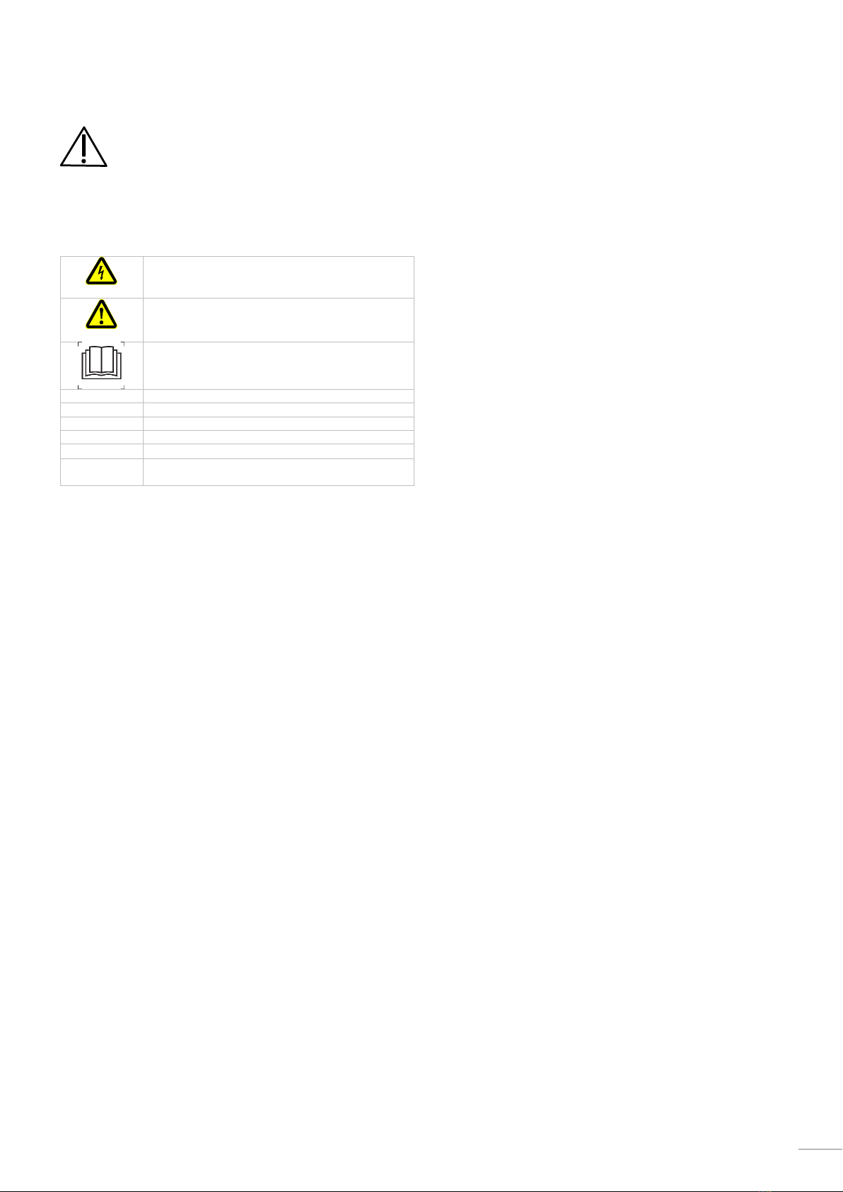
1.1 Explanation of symbols
The following symbols are used in these instructions:
Danger
Warning against potentially serious or fatal injuries
if the precautionary measures described are not
followed.
Caution
Warns against possible defects or damage of the
product if the described precautionary measures
are not followed.
Carefully read the safety notes and operating
instructions.
IMPORTANT
Important information is provided here.
INFO
Useful information is provided here.
These arrows indicate handling instructions.
This symbol indicates results of your actions.
This symbol indicates itemisations.
This symbol refers to a chapter with more detailed
information.
2 Safety notes
2.1 Proper use
The AT Excellence reverse osmosis device treats (demineralises)
mains water (max. 35 °C) for subsequent use in commercial
warewashers. The device reduces the overall salt content of the
mains water.
The device may be used only in conjunction with a commercial
warewasher.
The device is a technical device for commercial use and is not
intended for private use.
2.2 Improper use
The treated water may not be used as drinking water.
This device is not intended for use by per-
sons (including children) with limited physi-
cal, sensory or mental capabilities or who
do not have the required experience with
and knowledge of this device. Such persons
must either be instructed by a supervisor
who is responsible for their safety or must
be supervised during the operation of the
device.
Winterhalter Gastronom GmbH assumes no liability or warranty in
the event that the device is used improperly.
2.3 General safety notes
Carefully read the safety notes and operating instructions. Win-
terhalter Gastronom GmbH disclaims all liability or warranty if
these safety notes are not complied with.
Only use the device after you have read and understood the
operating instructions. Ensure you are instructed by the
Winterhalter Customer Service about the operation and function.
Only operate the device according to these operating instructions.
Train personnel in the operation of the device and refer to the
safety notes. Repeat the training sessions at regular intervals to
prevent accidents.
Keep the operating instructions accessible.
Do not make any changes, additions to or conversion of the
device without the approval of the manufacturer.
Original spare parts must be used for repairs or to replace con-
sumable parts.
If the mains cable is damaged, to prevent hazards it must be re-
placed by Winterhalter or its Customer Service or another qualified
person. The mains cable must be a H05RN-F type or equivalent.
Operate this device only when it is in perfect condition.
Danger of electric shock: Do not open any covers or panels if a
tool is required. Do not tamper with the electrical components of
the device; always call a qualified electrician.
Disconnect the water supply immediately if the device begins to
leak. Disconnect and isolate the device from power supply and
close the water stop cock.
In case of danger, switch off the device immediately. Pull out the
mains plug. Only then is the device free of voltage.
Never insert or pull out the mains plug with wet hands.
Never remove the plug from the socket using the cord.
Contact an authorised service technician for defects not caused by
the on-site water or electricity supply.
For your safety, test the on-site residual current circuit breaker
regularly by pressing the test button.
3 Requirements
Mains water
The quality of the mains water must conform to the requirements of
your water authority. In addition, threshold limits must be adhered
to ( 12).
Water connection and electrical supply
To maintain the membranes, automatic flushing takes place every
two hours in stand-by mode. For this reason, the device must remain
permanently switched on and the electricity and water supply must
be connected.
Warewasher connected to the device
The warewasher must fulfil the requirements of DIN EN 1717 or
respectively DIN EN 61770.
All components of the warewasher that come into contact with
water must be suitable for osmosis water. Use of non-ferrous met-
als is not permitted. Only synthetic components and stainless steel
components may be used.
The device should primarily be used in combination with a com-
mercial warewasher with a pressure-independent boiler. Operation
on warewashers with pressure boilers in conjunction with a pres-
sure expansion vessel is possible. The yield is reduced, however,
and the fill time of the warewasher is extended.
4 Before working with the device
Have the device connected in accordance with local standards
and regulations by authorised technicians (water, waste water,
electrical system) ( 13).
Have the device installed and commissioned by an authorised
service technician. Ensure you and your operating personnel are
trained in the operation of the device.

8
5 Product description
This water treatment device is based on the principle of reverse
osmosis (mechanical filtration). Initially, the water passes through an
active charcoal filter that filters out chlorine and sediment. The water
is then forced at high pressure through several membranes, which
removes almost all of its mineral content.
5.1 Dimensions and overview diagram
AT Excellence
-S
-M
Width
[mm]
205
365
Height
[mm]
420
420
Depth
[mm]
490
490
Item
Description
1
Mains cable
2
Operating panel ( 5.2)
3
Active charcoal filter (“Filter AC-M”)
4
Filter cover
IMPORTANT Never pick up the device by the filter cover (4).
5.2 Operating panel
Item
Description
1
Display
2
Buttons for navigation within the menu
3
Info button (display of additional information)
4
Confirmation button
5
On/off button
Display
Colour
Meaning
green
Device is ready for operation (stand-by mode).
blue
The device is in AquaOpt mode ( 6.2) or produc-
es osmosis water ( 6.3).
yellow
A warning is present; however, operation is still
possible ( 9.1).
red
An error exists, the device no longer produces
osmosis water ( 9.2).
not lit
Device is switched off.
6 Operation
6.1 Switching on the device
Press the button.
The display then lights up green and the greeting text ap-
pears.
The device is automatically in stand-by mode.
INFO To maintain the membranes, automatic flushing takes
place every two hours in stand-by mode.
6.2 AquaOpt
This function guarantees that a specified water quality is available for
washing. Water that does not correspond to this quality is automati-
cally flushed into the drain. The water volume and the flushing time
depend on the device’s selected quality and the downtime.
During flushing, the display lights up blue and the following picto-
gram appears:
Optimisation
water quality
Press the
button.
INFO Three different qualities are available (good, better, best).
The factory setting for quality is “better”.
Contact an authorised service technician if you want to change or
disable this function.
6.3 Production of osmosis water
As soon as the connected warewasher requests water, the device
first goes into AquaOpt mode. Then the production of osmosis water
begins. During this process, the display lights up blue and the follow-
ing pictogram appears:
Water
production
Press the
button.
6.4 Water quality display
After the device has produced osmosis water for at least 30 seconds
and production is finished, the water quality will be displayed for
several seconds on the display:
Water quality
Press the
button.
The more stars, the better the water quality (low conductivity). The
water quality depends on the condition of the membranes.
6.5 Switching off the device
To maintain the membranes, automatic flushing takes place every
two hours in stand-by mode. For this reason, the device must be
permanently connected to the electricity and water supply. When
required (e.g. overnight), however, the device can be switched off:
Press the button.
The display is not illuminated.
7 Production stops
Production stops of up to four weeks:
The device must be permanently connected to the electricity and
water supply.
INFO To maintain the membranes, automatic flushing takes
place every two hours in stand-by mode.
Production stops longer than four weeks:
Preservation required ( 8)

9
8 Preservation
The device must be preserved during production stops longer than
four weeks.
Contact an authorised service technician for preservation of the
device.
INFO In a preserved state, the device can be stored at tem-
peratures reaching -10 °C. If the production stop lasts
longer than nine months, the preservation must be re-
newed.
8.1 Checking the preservation
If a device is in a preserved state, the display is not lit. The remain-
ing preservation time can be displayed as follows:
Press the button.
Within the preservation time, the display lights up white and
the following two texts display alternately:
Preserved!
200 days
Commissioning:
Call the Service team!
INFO The device will automatically switch off after 5 seconds.
INFO If the preservation time has been exceeded, the display
lights up yellow and the following message appears:
Preservation
-3 days
8.2 Putting back into operation after preservation
Before the device can be put into operation after a period of preser-
vation, it must be flushed through.
Contact an authorised service technician to restart the device.
9 Warnings and errors
Danger
Danger of death: Live components!
Do not open any covers if you require a tool to do so.
There is a risk of electric shock.
Only an authorised service technician may work on the
electrical system. The device must first be disconnect-
ed from the electric network.
Caution
If you cannot correct the malfunction yourself:
Close the on-site water stop cock and switch off the
device.
Contact an authorised service technician.
Warewasher interface
The device can communicate directly with the Winterhalter ware-
washer (expected to be available for machines from October 2015).
In the event of a malfunction the following pictogram will appear on
the warewasher’s display:
Contact an authorised service technician to set up the interface.
9.1 Warnings
Warnings are displayed on the display as pictograms. The display
turns yellow (Exception: when in AquaOpt mode and during the
production of osmosis water, the display illuminates blue despite the
warning). Operation remains possible.
If several warnings occur at the same time, the pictograms will ap-
pear alternately.
INFO Press the button to display additional information to the
right of the pictogram.
AT Excellence-S only
Replace
filter!
Active charcoal filter exhausted
Change the active charcoal filter ( 10).
AT Excellence-M only
Replace
left filter!
Replace
right filter!
Active charcoal filter exhausted
Change left/right active charcoal filter ( 10).
Call the
Service team!
Different causes
Display the error code (9.3) and assign the repair to an author-
ised service technician.
Preservation
-3 days
Preservation time has been exceeded
Contact an authorised service technician to have the preservation
renewed.
Preservation
required!
Device without preservation minimum of 28 days without water
connection and electricity
Contact an authorised service technician immediately for the
preservation

10
9.2 Errors
Errors are displayed as pictograms. The display lights up red. The
production of osmosis water is stopped.
If several errors occur at the same time, the pictograms will appear
alternately.
INFO Press the button to display additional information to the
right of the pictogram.
AT Excellence-S only
Insert
filter!
Active charcoal filter is not fitted
The production of osmosis water is stopped.
Rectifying the cause of the error
Insert the active charcoal filter ( 10).
AT Excellence-M only
Insert
left filter!
Insert
right filter!
Active charcoal filter is not fitted
The production of osmosis water is stopped.
Rectifying the cause of the error
Insert the active charcoal filter ( 10).
Water pressure
too low!
On-site inlet pressure at the start of water production is too low
The production of osmosis water is stopped.
Rectifying the cause of the error
1
Check whether the water stop cock is open. If necessary, open
the water stop cock.
2
Switch off the device.
Close the water stop cock
Clean the dirt trap ( 13.5; item 1).
Open the water stop cock.
Switch on the device.
If the error continues, have the cause of the problem rectified by an
authorised service technician.
Call the
Service team!
Different causes of the error
The production of osmosis water is stopped.
Close the on-site water stop cock.
Switch off the device.
Immediately have the cause of the error rectified by an authorised
service technician.
9.3 Error memory
All warnings and errors are saved in the error memory. Every entry is
double-spaced and contains the following information: code, date,
time and error text
Accessing the error memory
Press the button.
INFO If a warning or an error is displayed, press the button
twice.
The error memory will be displayed.
newer entries
older entries
Display
Explanation
EVT
Warning
ERR
Error
Error/warning rectified
Leaving the error memory
Press the button twice.
10 Changing the active charcoal filter
Caution
If the active charcoal filter is not changed in time, the
membranes can be damaged or the water flow could
decrease. This decreases the water quality and impairs
the washing result.
Change the active charcoal filter in good time.
The active charcoal filter is a wear part and must be replaced annu-
ally or when the following message is displayed:
AT Excellence-S
AT Excellence-M
or
Changing the filter
INFO A small amount of water will be expelled during the filter
change.
Take off the filter cover located at the front of the device.
Change the filter cartridge as follows:
Turn the filter
cartridge to the
left up to the
stop.
Firmly pull the
filter cartridge
out of the
holder.
Firmly push
the new filter
cartridge into
the holder.
Turn the filter
cartridge to the
right up to the
stop.
The device will carry out automatic flushing (approx. 1 minute).
Fit the filter cover.

11
11 Servicing and maintenance
Caution
Do not spray the device and the surrounding area
(panels, base) using a water hose, steam-jet air ejec-
tor or high-pressure cleaner.
Clean the control panel and filter cover with a damp cloth.
Clean the stainless steel coverings with a stainless steel cleaner.
We recommend using Winterhalter C 122 universal grease solvent
and stainless steel cleaner such as Winterhalter C 162 Stainless
Steel Polish in the pressurized spray can.
Do not use corrosive products, acids, steel wool or wire brushes.
Do not use abrasives or abrasive cleaners.
We recommend that you have an authorised service technician
service the device at least once a year.
Cleaning/descaling breather
Check the breather (1) every six months for
dirt and scaling.
Where required, clean, and/or descale with a
standard decalcification agent.
If necessary, commission a service technician
to carry this out.
Consumable parts
The following parts are consumable partss and must be replaced at
regular intervals.
Description
Note
Active charcoal filter
Exchange annually ( 10).
Membranes
If the following warning appears on the display:
Call the
Service team!
Access the error memory ( 9.3).
If the EVT 24 is listed, the membranes must be
replaced by an authorised service technician.
12 Technical data
AT Excellence
-S
-S
Height
420 mm
Width
205 mm
365 mm
Depth
490 mm
Type of protection
IP X5
Weight
19 kg
33 kg
Admissible noise level under normal oper-
ating conditions
< 55 dB(A)
< 62 dB(A)
Filter capacity (1 mg/l Cl2)
4.8 m³
Operating conditions
Operating temperature
0 – 40 °C
Relative air humidity
< 95 %
Storage temperature in preserved
condition
> -10 °C
Maximum height of the installation location
above sea level
3000 m
Threshold values for the mains water
-S
-M
Maximum inlet water temperature
35 °C
Minimum flow rate
360 l/h
720 l/h
Minimum flow pressure
120 kPa
(1.2 bar)
150 kPa
(1.5 bar)
Maximum inlet pressure
600 kPa (6.0 bar)
Maximum total hardness (TH)
35 °dH
Electrical conductivity (at 25 °C)
< 1200 µS/cm
Chlorine
< 0.2 mg/l
Silicates (as SiO2)
< 30 mg/l
Power supply
-S
-M
Voltage
200–240 V
Frequency
50 / 60 Hz
Power consumption
1.4 – 2.0 A
2.7 – 4.0 A
Fuse (electronic operating panel)
6.3 A mT
Water dispenser
-S
-M
Volume flow of osmosis water at an inlet
water temperature of 15 °C
at least
90 l/h
at least
180 l/h
Yield
The yield depends upon the total hardness (°dH) and the conductivi-
ty (µS/cm) of the mains water. During commissioning, the authorised
service technician will install the correct capillary in the interior of the
device.
13 Installation and connection
13.1 Installation
The device must be installed in an upright position. The maximum
permitted tilted position is 10 mm.
The installation site must be frost-resistant to keep the water
supply systems from freezing.
13.2 Dimensions and position of the connections
AT Excellence-S
AT Excellence-M
Rear view
Item
Description
A
Water inlet (mains water) G ¾“, external thread
B
Water drain (waste water), DN 10
C
Water outlet (osmosis water) G ¾” external thread
D
Mains cable
E
Warewasher interface
F
Connection for on-site equipotential bonding system

12
13.3 Electrical connection
Danger
Danger of death: Live components!
The device must be connected by a qualified in accord-
ance with local or national regulations.
Notes for the electrician:
Only connect to alternating current ensuring the socket is correctly
earthed.
Electrical installation must be carried out according to the details
on the type plate.
Install a residual current circuit breaker with a release current of
30 mA in the electrical cables.
Only for Japan and Mexico:
Permanently install the mains cable in place or mount an appro-
priate plug connector.
Connecting the device
Plug in the mains cable to the device and the on-site power socket.
Install cable tie (1) for strain relief.
Connect the device to the on-site equipotential bonding system.
The connection screw (2) is on the rear of the device and is
marked with the symbol (3).
13.4 Replacing the mains cable
If the mains cable is damaged, to prevent hazards it must be re-
placed by Winterhalter or its Customer Service or another qualified
person. The mains cable must be a H05RN-F type or equivalent.
The mains cable is available at Winterhalter.
Plug in the mains cable to the device.
IMPORTANT Install cable tie (1) for
strain relief and pull
tightly.
Plug in the mains cable to the on-site
power socket.
Rear view
13.5 Water connection
Caution
The device must be connected to the mains inlet and
waste water by a qualified plumber in accordance with
local or national water regulations.
National installation and operation regulations must be
observed.
Caution
The inlet water hose may not be shortened or damaged.
Old existing hoses may not be re-used.
Do not bend the inlet water hose while laying it.
INFO An EA type backflow preventer is installed in the interior of
the device.
Follow the threshold values for the mains water ( 12). If neces-
sary, consult the local Winterhalter subsidiary.
Carry out connection according to the diagram:
IMPORTANT In order for the device to operate properly, a suit-
able dirt trap (1) must be fitted at the water intake
point.
Item
Description
A
Water inlet (mains water)
B
Water drain (wastewater)
C
Water outlet (osmosis water)
G
Water stop cock
H
On-site drain
1
Dirt trap
2
Inlet water hose (supplied with the device)
3
Waste water hose
4
Breather
5
Hose from the warewasher
Check that the connections are tight.
Additional information:
Installation in Great Britain:
An ED type backflow preventer with WRAS approval must also be
installed between the dirt trap and the inlet water hose.
For warewashers with pressure boiler:
Install the pressure expansion vessel between the AT Excellence
and the warewasher (see the connection diagram) (kit pressure
expansion vessel 5101127).
14 Disposal
Contact your dealer so that the materials in the device can be fed
back into the material cycle as soon as possible.
to the warewasher
Subject to technical alterations
89013775-00/2016-11


Winterhalter Gastronom GmbH
Gewerbliche Spülsysteme
Winterhalterstraße 2–12
88074 Meckenbeuren
Deutschland
Telefon +49 (0) 75 42/4 02-0
www.winterhalter.de
Winterhalter Gastronom GmbH
Commercial Dishwashing Systems
Winterhalterstrasse 2–12
88074 Meckenbeuren
Germany
Telephone +49 (0) 75 42/4 02-0
www.winterhalter.biz
Technische Änderungen vorbehalten
Right to make technical modifications is reserved
89013775-00/2016-11
This manual suits for next models
1
Table of contents
Other Winterhalter Water Filtration System manuals