WIRTH OKTOPUS GL-R600 User manual

O p e r a t i n g i n s t r u c t i o n s
Pneumatic lifting device
for prefabricated glass and facade elements
OKTOPUS®GL-R600
Serial number: _______________
Technical documentation
1 98 900 002 a
08/2010
This technical documentation corresponds to the state as per the date of issue.
WIRTH GMBH
INSTALLATION SYSTEMS DIVISION
Brehnaer Straße 1
D-06188 Landsberg
Phone +49 (0) 34 602 / 70 88 - 0
Fax +49 (0) 34 602 / 70 88 - 111
www.wirth-gmbh.com
Original instructions
Protected according to ISO 16016

Operating Instructions
OKTOPUSGL-R600
Technical documentation
1 98 900 002 a
Page 2 of 26
Page
Table of contents 2
1 General information regarding OKTOPUS®4
1.1 Manufacturer information 4
1.2 Service workshop 4
1.3 Scope of application 4
2 Proper use of OKTOPUS®GL-R600 5
2.1 Basic principle and safety concept for the OKTOPUS®system 5
2.2 Safety instructions 6
2.3 Design and use of the OKTOPUS®GL-R600 9
2.4 Conditions and restrictions for the use of the system 12
2.5 Transport and storage 12
3 Instructions for the use of the OKTOPUS®GL-R600 13
3.1 Electricity supply 13
3.2 Vacuum supply 14
3.3 Control panel/switch 15
3.4 Start-Up 15
3.5 Handling of glass and facade elements 16
3.5.1 Handling of lying glass and facade elements 16
3.5.2 Handling of glass and facade elements in vertical positions 17
3.5.3 Rotating a load hanging in a vertical position with the OKTOPUS®GL-R600 18
with crane arm
3.5.4 Rotating a load hanging in a vertical position with the OKTOPUS®GL-R600 18
with guide ring
3.5.5 Swivelling a load hanging in a vertical position with the OKTOPUS®GL-R600 19
with crane arm
3.6 Converting the OKTOPUS®GL-R600 into the different versions 20
3.6.1 Assembly of the guide ring 20
3.6.2 Assembly of the crane arm 20
3.6.3 Assembly of the extension arms 20
4 Maintenance and servicing 22
4.1 General information 22
4.2 Mechanical components 22
4.3 Vacuum system 23
4.4 Electrical and electronic components 24
5 Conduct in the event of faults 26
Appendix 1: Short version of the operating instructions for OKTOPUS®GL-R600
Appendix 2: Summary of the safety instructions
Appendix 3: EC Declaration of Conformity
Appendix 4: Test mark as per the Directive 2006/42/EC

Operating Instructions
OKTOPUSGL-R600
Technical documentation
1 98 900 002 a
Page 3 of 26
Page
List of illustrations 3
Fig. 1 OKTOPUS®GL-R600 with crane arm 9
Fig. 2 OKTOPUS®GL-R600 with crane arm and extension arms 10
Fig. 3 OKTOPUS®GL-R600 with guide ring 10
Fig. 4 Load carrying device OKTOPUS®GL-R600 with crane arm 11
Fig. 5 Load carrying device OKTOPUS®GL-R600 with guide ring 11
Fig. 6 Charge indicator 13
Fig. 7 Vacuum gauge 14
Fig. 8 Control panel 15
Fig. 9 OKTOPUS®GL-R600 with glass element 17
Fig. 10 OKTOPUS®GL-R600 with glass element and extension arms 17
Fig. 11 OKTOPUS®GL-R600 with guide ring respectively crane arm 18
Fig. 12 OKTOPUS®GL-R600 guide ring, with crane arm, with crane arm
and extensions 19
Fig. 13 OKTOPUS®GL-R600 during the swivelling movement 19
Fig. 14 Assembly of the extension arms 21
Fig. 15 Suction cup 23
Fig. 16 Battery charger 24
Fig. 17 Alarm devices 26

Operating Instructions
OKTOPUSGL-R600
Technical documentation
1 98 900 002 a
Page 4 of 26
1 General information regarding OKTOPUS®
1.1 Manufacturer information
Manufacturer’s name and registered office:
WIRTH GMBH
Installation Systems Division
Brehnaer Straße 1
D-06188 Landsberg
Device characteristics:
Product denomination: OKTOPUS®GL-R600
Type: OKTOPUS®GL-R600 R M B24 P 110
Serial number: (see type plate)
Year of manufacture: (see type plate)
Mass: approx. 79 kg (with extension arms, 8 suction cups)
approx. 54 kg (without extension arms, 4 suction cups)
approx. 67 kg (with guide ring, 4 suction cups)
Safe Working Load: 300 kg (4 suction cups ∅400 mm)
600 kg (8 suction cups ∅400 mm)
CE mark: as per EC declaration of conformity, Appendix 3
Short summary of safety instructions on every device as per Appendix 2.
Test card for test badge according to the EC directive 2006/42/EC optionally available for
every device as per Appendix 4.
1.2 Service workshop
WIRTH GMBH Phone: +49 (0) 34 602 / 70 88 - 0
Brehnaer Str. 1 Fax: +49 (0) 34 602 / 70 88 - 111
1.3 Scope of application
This operation manual represents the state-of-the-art and the safety measures defined by the
European Machine Directive valid at the editing date of the manual.
Diverging or amending national regulations may not be considered eventually.
The user is responsible exclusively to observe such regulations.

Operating Instructions
OKTOPUSGL-R600
Technical documentation
1 98 900 002 a
Page 5 of 26
2 Proper use of OKTOPUS®GL-R600
2.1 Basic principle and safety concept for the OKTOPUS® system
The OKTOPUSsystem units are "load suspension devices" which operate in accordance
with the "suction lifting" principle. They will be mounted to a hoist or they work as a Stand-
Alone-Device and serve for manipulation and positioning of large-sized construction ele-
ments.
The basic principles of operation of the OKTOPUSsystem are:
⇒controlled suction and release of large construction elements having sufficient inherent
stability with one or more vacuum suction cups,
⇒transport and positioning of the suctioned construction elements by manipulation of the
OKTOPUS,
⇒fine positioning of the construction elements with the control of the OKTOPUS®-axes (if
available).
The OKTOPUS®system is offered in various types of design and models for different
spheres of application. These differ depending on the used hoist, the lifting loads, the neces-
sary positioning movements and the used controls.
For further information please do not hesitate to contact us (www.wirth-gmbh.com).
The special function of the OKTOPUS®system as a “load carrying attachment“ results in
specific safety requirements which have been taken into account during construction, execu-
tion as well technical documentation and in drawing up the operating instructions for the OK-
TOPUS®system.
Therefore, strict compliance with the instructions and information for proper and safe use of
the device provided in the operating instructions is a prerequisite for the manufacturer’s war-
ranties during the warranty period agreed on.
The OKTOPUS®user is responsible for combining the OKTOPUS®system with a crane or an
elevator. The user is responsible for proper implementation of the relevant guidelines and in-
structions. The information provided by the manufacturer of the OKTOPUS®system with
these operating instructions are a supplement to support the user in this.
Before initial commissioning of the system, skilled staff has to check at the user’s premises
whether the combination of OKTOPUS®system / crane or hoist is suitable for use.
Moreover, the OKTOPUS®has to be subjected to tests by an expert at regular intervals
(please see item 4.1 regarding this topic). Experts are those persons who have sufficient
knowledge in the field of load carrying units on account of their education and experience in
the subject concerned and are acquainted with the relevant safety-at-work instructions and
safety precautions, guidelines and generally accepted engineering standards to such a de-
gree that they can evaluate the state of the load carrying units as being safe for operation.
Initial testing of the crane or hoist/OKTOPUS®combination as well as successful completion
of the annual test of the OKTOPUS®system by an expert have to be documented.
The manufacturer of the OKTOPUS®system offers expert testing as a service and docu-
ments testing of the OKTOPUS®by placing the test mark on the test card in accordance with
Appendix 4 and indicating the date for the next test.

Operating Instructions
OKTOPUSGL-R600
Technical documentation
1 98 900 002 a
Page 6 of 26
2.2 Safety instructions
(1) Only use cranes with a CE mark and a load bearing capacity exceeding the live
load of the OKTOPUS®GL-R600 in all working positions by at least 100 kg!
(2) Never use a damaged, not fully functional or not complete OKTOPUS®.
(3) Before using the crane/OKTOPUS®working arrangement for the first time always the
units have to be checked by an expert and this inspection has to be documented!
(4) Only operate the crane if you hold a suitable licence!
(5) Only operate the OKTOPUS®and the crane, if you are familiar with the control and
display elements as well as the operating instructions. You need to be aware of
the impact a function can have on the entire equipment.
(6) Before using the OKTOPUS®and the crane check the function of the operating and
indicating elements as well as the alarm features!
(7) Make sure that the crane operator has a sufficient view over the sling and assembly
location.
(8) Arrange hand signals with the installer and fitter for the necessary crane operations!
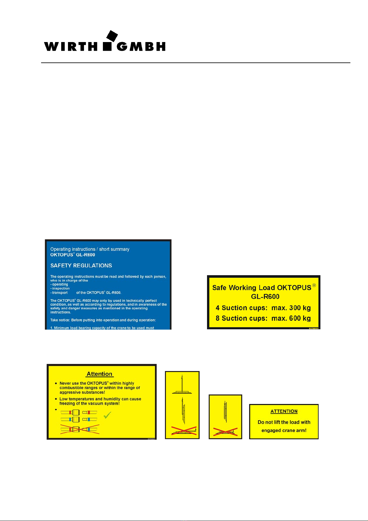
(9) Consider absolutely the maximum load-bearing capacities of the OKTOPUS®GL-R600
described in this section under the point Information Signs! The data are valid only for a
working height which corresponds to the sea level!
(10) Should be protection hoods on the suction heads, the protection hoods must remove
before start-up!
(11) Only work in wind strengths of less than 36 km/h, else the load is endangered of
swinging uncontrollably.
(12) Check the suction pads daily for damage; if necessary replace with new pads.
(13) Clean the suction surfaces on the elements. Do not place the suction pads on protec-
tive film, but remove the film beforehand, at least at the contact areas of the suction
pads.
(14) Never stand or walk under the suspended load!
(15) Ensure that no-one attempts to mount or ride on the OKTOPUS®GL-R600 or the
suspended construction elements.
(16) Stop work immediately when the acoustic alarm sounds and the warning light
lights up! In this case there are the danger of a grave damage to the system and fal-
ling of the sucked load. Use the elevating machine to put down the OKTOPUS®and
the sucked load carefully. Find and remove the cause for the alarm. In case the defects
cannot be removed, finish working with the OKTOPUS®immediately. The OKTOPUS®
has to be secured against further use.
(17) In the event of faults and during servicing and maintenance work always switch the
OKTOPUS®off. Turn therefor the main switch to the OFF position!
(18) Please note, low temperatures and humidity can cause freezing of the vacuum
system!
(19) Never use the OKTOPUS®within highly combustible ranges or within the range of
aggressive substances!
(20) Wet components must not be sucked in, because:
a. this reduces the load bearing capacity considerably and
b. the vacuum system and/ or the control system of the OKTOPUS®might be dam-
aged!
(21) Never attempt to lift damaged glass or facade elements.
(22) After use protect the suction cups of the OKTOPUS®against damage by using protec-
tion hoods!

Operating Instructions
OKTOPUSGL-R600
Technical documentation
1 98 900 002 a
Page 7 of 26
(23) Do not lift the load higher than necessary.
(24) Never leave a lifted load unsupervised.
(25) In each case wear suitable protection clothes, helmets, gloves and industrial safety
shoes!
(26) Lift never more than one glass or facade element at the same time.
(27) Always comply with the prescribed maintenance instructions:
•daily visual and functional test (charge level of the battery, vacuum gauges, suc-
tion cups, red warning light, green signal light, acoustic alarm, manual control)!
•depending on the operating conditions, however at least annually, inspection by a
qualified expert!
(28) Never modify the OKTOPUS®in such a way, that its safety is impaired. The manu-
facturer's warranty is otherwise rescinded.
(29) Never remove information signs, safety signs and test card (with test badge) from
the OKTOPUS®! The manufacturer's warranty is otherwise rescinded.
The following safety-related signs and pictograms are mounted on the OKTOPUS®:
Information Signs
(Abstract of the operating manual, (Safe Working Load OKTOPUS®)
refer to Annex 2)
(Warning notices)

Operating Instructions
OKTOPUSGL-R600
Technical documentation
1 98 900 002 a
Page 8 of 26
Test card in accordance with Annex 4
(Beware of suspended
load)
(Beware of batteries) (Test card)
(General notice)

Operating Instructions
OKTOPUSGL-R600
Technical documentation
1 98 900 002 a
Page 9 of 26
2.3 Design and use of the OKTOPUS®GL-R600
The OKTOPUS®GL-R600 is a load carrying attachment of modular design for large, suffi-
ciently stable glass and facade elements with a surface which is at least on one side partially
smooth and airtight.
On principle, it can be used for wall and roof assembly.
Depending on the actual application, three versions of the OKTOPUS®GL-R600 are
available:
OKTOPUS®GL-R600 (see Fig. 1)
•base frame with a centrally mounted rotating and swivelling crane arm
OKTOPUS®GL-R600 with extension arms (see Fig. 2)
•base frame with a centrally mounted rotating and swivelling crane arm
•4 items of extension arms
OKTOPUS®GL-R600 with guide ring (see Fig. 3)
•base frame with infinitely rotatable guide ring guided in four rollers with 2 crane eyes
•locking lever with brake pads
Fig. 1: OKTOPUS®GL-R600 with crane arm
1 Crane eye
2 Crane arm
3 Vacuum gauge
4 Vacuum reservoir
5 Release “Swivelling“
6 Swivel joint
7 Control panel/switch
8 Suction cup
9 Battery load socket
10 Main switch
11 Green Signal light
12 Charge indicator
13 Red Warning light
14 Release “Rotating“
4
3
1
2
5
11
13
7
9
3
4
12
8
14
6
10

Operating Instructions
OKTOPUSGL-R600
Technical documentation
1 98 900 002 a
Page 10 of 26
Fig. 2: OKTOPUS®GL-R600 with crane arm and extension arms
Fig. 3: OKTOPUS®GL-R600 with guide ring
1 Crane eye
2 Crane arm
3 Release “Swivelling“
4 Swivel joint
5 Release “Rotating“
6 Extension arm with suc-
tion cup
1
2
3
5
4
6
1 Crane eye
2 Guide ring
3 Brake
4 Locking lever guide ring
1
2
1
4 3

Operating Instructions
OKTOPUSGL-R600
Technical documentation
1 98 900 002 a
Page 11 of 26
The load carrying attachment OKTOPUS®GL-R600 has been designed as an attachment
device and is mounted to the crane in accordance with Fig. 4 and Fig. 5.
Fig. 4: Load carrying device OKTOPUS®GL-R600 Fig. 5: Load carrying device OKTOPUS®GL-R600
with crane arm with guide ring
The use of the load carrying attachment system OKTOPUS®offers the following benefits dur-
ing the assembly of large sized glass and facade elements:
•faster, more rational and more efficient assembly process,
•smaller assembly team required,
•higher quality of the process on account of careful handling which protects materials,
•lower physical strain on the fitters because they don’t have to carry and lift heavy loads,
•high degree of safety at work.
lifting tackle
Suction cup
Glass element
Crane arm
lifting tackle
Suction cup
Glass element
Guide ring

Operating Instructions
OKTOPUSGL-R600
Technical documentation
1 98 900 002 a
Page 12 of 26
2.4 Conditions and restrictions for the use of the system
The glass and facade elements to be processed with the OKTOPUS®GL-R600 have to fulfil
the following criteria in the suction areas:
•they have to be airtight,
•they must have an smooth, dry, oil-free and clean surface and
•they must not be equipped with a protective plastic film.
The OKTOPUS®is delivered with suction cups for smooth glass and facade elements.
In case profile boards (e. g. with a trapezoidal cross section) are to be transported, special
vacuum cups adapted to that end have to be used, which can be provided by the manufac-
turer of the OKTOPUS®system as a customer specific option.
Suction of oil, water, fumes or aggressive gasses should be avoided. The ambient tempera-
ture must not exceed 40°C. In temperature conditions of < 8°C the capacity of the batteries
used is reduced. The air-borne sound emitted by the OKTOPUS®GL-R600 amounts to < 70
dB(A), vibrations amount to < 2.5 m/s2, so that no specific protective measures are required
on account of that.
The scope of application of the OKTOPUS®GL-R600 is limited by the maximum bearing ca-
pacity (refer section 2.2 Safety Notes/Information Signs) and the performance data and op-
erating conditions of the employed crane and site conditions. Furthermore it is to be made
sure that the elements which should be processed are sufficiently stable in itself and suitable
for the installation with vacuum lifting devices (If necessary clarify it with the manufacturer of
the elements.).
Because of the large variety of elements and surface coatings at the market we cannot as-
sume the liability for possibly occurring material incompatibilities between the surface coating
of the element and the suction rubber of our vacuum pads.
The maximum bearing capacities marked on the OKTOPUS®applies only on use of the
original suction cups and when the device is used in a working height which corresponds to
the sea level. If the OKTOPUS®is to be used in larger heights, then please contact the Wirth
service team first.
2.5 Transport and storage
The OKTOPUS®must only be moved with a suitable crane or elevator means of transport
having a sufficient load-bearing capacity.
Switch off the OKTOPUS®during transport! For it turn the main switch to
the OFF position!
Protect the rubber lips of the suction cups against pollution and damage by
covering them with protective coverings.
In order to prevent the destruction of the batteries through discharge dur-
ing storage, the OKTOPUS®needs to have a continuous connection to the
charger which has to be switched on and ready for operation.
ATTENTION
ATTENTION
ATTENTION

Operating Instructions
OKTOPUSGL-R600
Technical documentation
1 98 900 002 a
Page 13 of 26
3 Instructions for use of the OKTOPUS®GL-R600
3.1 Electricity supply
The supply of electricity is provided by a 24 V / 7 Ah battery (2 items of 12 V batteries con-
nected in series).
The charging status of the battery is supervised and protected by a charge indicator. It is dis-
played with the help of light emitting diodes (LED) in the signal colours yellow and red (Fig.
6). A chain consisting of seven yellow LEDs shows the respective residual charge of the bat-
tery when certain charging limits are reached. The LEDs go out one after another in the
course of the continuing discharge of the battery.
In order to monitor the charging status of the battery the charge indicator provides you with
the following information:
⇒In case of a discharge of ca. 70% the LED on the extreme left of the display starts
flashing (advance warning).
⇒In case of a discharge of ca. 80% the last yellow LED goes out and the red LED is
switched on. The alarm is switched on. The alarm can be deactivated by finishing the
work and switch off the device. The battery has to be recharged.
⇒In case the red LED does not go out after the battery has been charged, the battery
voltage is not sufficient to reset the charge indicator. There is either a defect in the
charger or in the battery system.
The charge indicator is located according to Fig. 1.
Fig. 6: Charge indicator
In case the red LED lights up, finish or interrupt the work forthwith, leave
the danger area and lower the load.
1 red LED
7
y
ellow

Operating Instructions
OKTOPUSGL-R600
Technical documentation
1 98 900 002 a
Page 14 of 26
3.2 Vacuum supply
The vacuum supply is provided by an electrically operated vacuum pump, which is supplied
by the battery. Starting from the vacuum pump the OKTOPUS®GL-R600 is developed as a
dual circuit system. That means, all following vacuum modules, like non-return valve, vac-
uum reservoir, water separator and suction cups are two times present (2 vacuum circles).
At the OKTOPUS®GL-R600 the 2 vacuum circles are marked by different colors, one color
per vacuum circuit (usually blue and red). It is to be made sure that only vacuum hoses and
vacuum hose couplings of equal color are interconnected.
When mounted on the crane the OKTOPUS®GL-R600 is ready for operation when sufficient
vacuum is provided in both vacuum reservoirs. The current vacuum level is constantly indi-
cated on the two vacuum gauges (Fig. 7).
The green scale range is the
permissible working range from -0.65 bar to -0.9 bar.
Fig. 7: Vacuum gauge
During operation the vacuum is monitored by two pressure control devices. If the vacuum is
in both vacuum circles in the working area, the green signal light shines. The OKTOPUS®is
ready for use. If the vacuum drops in one or both vacuum circles below the prescribed level
(exceeds the pressure the -0.65 bar mark = red scale range), an alarm is automatically acti-
vated:
⇒the acoustic alarm sounds,
⇒the red warning light lights up.
Connect only vacuum hoses respectively vacuum hose couplings of the
same color!
If the alarm is activated stop work immediately and evacuate the hazard
zone, as suctioned elements could suddenly be released.
The alarm remains active until the pneumatic pressure is restored to within
the permitted limits.
ATTENTION
ATTENTION
ATTENTION
Green range
The OKTOPUS®GL-R600
may be operated only
within this range.
Red range
The OKTOPUS®GL-R600
must not be operated in
this range!

Operating Instructions
OKTOPUSGL-R600
Technical documentation
1 98 900 002 a
Page 15 of 26
3.3 Control panel/switch
The OKTOPUS®GL-R600 is operated with a control panel in accordance with Fig. 8.
Fig. 8: Control panel
3.4 Start-Up
Proceed as follows to start operation of the OKTOPUS®:
•Turn the main switch to the "ON“ position.
•Place the OKTOPUS®on the load!
•Push the switch SUCTION / RELEASE toward SUCTION!
•Check the charge level of the battery on the charge indicator,
⇒the unit is ready for operation when the yellow LEDs lights up
⇒if the left-hand yellow LED flash and/or the red LED lights up (alarm is given at the
same time), charge the battery!
•Check the vacuum on the vacuum gauges,
⇒if the pressure is on both gauges in the green range, the unit is ready for operation!
⇒if the pressure is on one or both gauges in the red range, the alarm is activated and
the vacuum must build up first.
−Vacuum is built up to -0.73 bar, red warning light goes out, the green signal light
goes on.
Switch SUCTION / RELEASE

Operating Instructions
OKTOPUSGL-R600
Technical documentation
1 98 900 002 a
Page 16 of 26
3.5 Handling of glass and facade elements
In order to get the OKTOPUS®GL-R600 ready for operation, first of all it has to be coupled to
the crane as a load carrying device.
The assembly of the OKTOPUS®has to be carried out while the crane is immobile and the
OKTOPUS®is switched off.
The assembly of the building elements is carried out as follows:
Make sure that the load is placed properly on the OKTOPUS®. Unbalanced
loads can tilt or turn unexpectedly.
3.5.1 Handling of lying glass and facade elements
⇒In order to suck in a lying load, you need the OKTOPUS®GL-R600 in the variant with
crane arm or with crane arm and extensions (see Fig. 9, 10).
Never use the OKTOPUS®with mounted guide ring for lifting or erecting of
a horizontal lying load!
⇒Unlock the release "swivelling" (see Fig. 9) and bring the crane arm into a vertical posi-
tion. Now move the crane with the mounted OKTOPUS®GL-R600 to the elements.
Place the OKTOPUS®on the topmost element.
Never attempt to lift a lying load
if the pivoting of the crane
arm is latched!
⇒Place the OKTOPUS®above the centre of mass (±5 cm) of the load.
⇒Push the switch SUCTION / RELEASE toward SUCTION (see Fig. 8).
⇒After the warning light and the horn have both gone out and the vacuum gauge indi-
cates that the working range has been reached (see Fig. 7) and you have made sure,
that no one is present in the danger area, you can lift the load.
⇒Only lift the load as high as necessary!
⇒After the element has been placed at the assembly location, it has to be fastened com-
pletely!
⇒After that the building elements are detached. For release raise the switch SUCTION /
RELEASE somewhat and push it toward RELEASE. The raising of the switch is an ad-
ditional safety device against unintentional faulty operation.
Due to the dead weight of the OKTOPUS®a remainder vacuum is present
also after ventilating the suction cups by the evacuated system. Jerky rais-
ing of the OKTOPUS®strengthens this effect. Take the equipment off there-
fore always slowly and evenly from the shifted elements!
ATTENTION
ATTENTION
ATTENTION
ATTENTION

Operating Instructions
OKTOPUSGL-R600
Technical documentation
1 98 900 002 a
Page 17 of 26
Fig. 9: OKTOPUS®GL-R600 with Fig. 10: OKTOPUS®GL-R600 with glass
glass element element and extension arms
3.5.2 Handling of glass and facade elements in vertical positions
⇒Move the crane with the mounted OKTOPUS®GL-R600 to the elements. Place the
OKTOPUS®on the topmost element.
⇒Place the OKTOPUS®on or above the centre of mass of the load (max. ±5 cm).
In order to avoid an unintentional rotation, it must be ensured that the
unlocking lever “Rotating” (see Fig. 11) is engaged. The unlocking lever
“Swivelling” must be disengaged and the crane arm must stand perpen-
dicularly!
⇒Push the switch SUCTION / RELEASE toward SUCTION (see Fig. 8).
⇒After the warning light and the horn have both gone out and the vacuum gauge indi-
cates that the working range has been reached (see Fig. 7) and you have made sure,
that no one is present in the danger area, you can lift the load.
⇒Only lift the load as high as necessary!
⇒After the element has been placed at the assembly location, it has to be fastened com-
pletely!
⇒After that the building elements are detached. For release raise the switch SUCTION /
RELEASE somewhat and push it toward RELEASE. The raising of the switch is an ad-
ditional safety device against unintentional faulty operation.
1 Crane eye
2 Crane arm
3 Release “Swivelling“
4 Glass element
1 Crane eye
2 Crane arm
3 Release “Swivelling“
4 Glass element
5 Extension arm
ATTENTION
5
1
2 3
3
1
2
3
4

Operating Instructions
OKTOPUSGL-R600
Technical documentation
1 98 900 002 a
Page 18 of 26
Due to the dead weight of the OKTOPUS®a remainder vacuum is present
also after ventilating the suction cups by the evacuated system. Jerky rais-
ing of the OKTOPUS®strengthens this effect. Take the equipment off there-
fore always slowly and evenly from the shifted elements!
Fig. 11: OKTOPUS®GL-R600 with guide ring respectively crane arm
3.5.3 Rotating a load hanging in a vertical position with the OKTOPUS®GL-R600 with
crane arm
⇒Suck the element as described in 3.5.2!
Never unlock the release for “Rotating“ and “Swivelling“ at the same time.
If both releases are unlocked, the device and/or the load might be dam-
aged!
⇒Before rotating the load, make sure that enough space is available for manoeuvring.
Make sure that the load does not hit anything during turning!
⇒Unlock the release “Rotating“ (see Fig. 11) and turn the load into the required position.
Afterwards make sure the release handle catches hold again. The rotational axis is
equipped with a 8 x 45° grid.
3.5.4 Rotating a load hanging in a vertical position with the OKTOPUS®GL-R600 with
guide ring
⇒Suck the element as described in 3.5.2!
⇒Place the OKTOPUS®on or above the centre of mass of the load (max. ±5 cm).
In order to avoid an inadvertent turning of the load, you have to make sure
that the locking lever for the guide ring (see Fig. 11) is pulled on!
⇒Before turning the load, make sure that enough space is available for manoeuvring.
Make sure that the load does not hit anything during rotating!
⇒Release slowly the locking lever for the guide ring (see Fig. 11) by turning to the left!
⇒Turn the load into the required position.
⇒Relock the brake by turning the lever to the right!
1 Brake
2 Locking lever guide ring
3 Release “Rotating“
4 Release “Swivelling“
ATTENTION
ATTENTION
2 1 3 4
ATTENTION

Operating Instructions
OKTOPUSGL-R600
Technical documentation
1 98 900 002 a
Page 19 of 26
Fig. 12: OKTOPUS®GL-R600 guide ring, with crane arm, with crane arm and extensions
3.5.5 Swivelling a load hanging in a vertical position with the OKTOPUS®GL-R600 with
crane arm
⇒Suck the element as described in 3.5.2!
Never attempt to unlock release “Swivelling“ (see Fig. 11) if it carries a
load. This would cause uncontrollable “downward tilting” of the load!
In order to swivel the load from a vertical into a horizontal position, at least
3 persons are needed. Two persons have to secure and guide the load, the
third person has to operate the interlock release!
⇒Before swivelling the load you have to take account of the fact that the swivelled load
needs more horizontal space. Make sure that the load does not hit anything during
swivelling!
⇒Unlock the release “Swivelling“ (see Fig. 11) and move the load into a suitable position
and let the bolt engage in an appropriate position.
Fig. 13: OKTOPUS®GL-R600 during the swivelling movement
ATTENTION
ATTENTION
Glass element

Operating Instructions
OKTOPUSGL-R600
Technical documentation
1 98 900 002 a
Page 20 of 26
3.6 Converting the OKTOPUS®GL-R600 into the different versions
3.6.1 Assembly of the guide ring
⇒Place the OKTOPUS®GL-R600 in a flat position on a clean and even surface (suction
cups pointing down).
⇒Fix two rollers in two adjoining roller housings. Use therefor the provided special
screws and the M10 nuts.
⇒Push the remaining 2 rollers loosely into the still available roller housings.
⇒Place the guide ring in the slots of the two firmly mounted rollers.
⇒Position now the two loose rollers in such a way that the guide ring runs in the slots.
Fix the rollers with the remaining 2 special screws and the nuts M10.
⇒Install the "brake shoes" contained in the scope of supply and the "locking lever guide
ring" by means of the screws, washers and nuts (likewise contained in the scope of
supply) (see Fig. 11).
⇒Check proper seat of the guide ring, of the rollers as well as of the washers and the
nuts once again!
3.6.2 Assembly of the crane arm
⇒Place the OKTOPUS®GL-R600 in a flat position on a clean and even surface (suction
cups pointing down).
⇒In case the guide ring is assembled, dismantle it as follows:
- Remove the special screws of two adjoining roller.
- Push the two loose rollers away from the supporting ring into the roller housings.
If possible, two persons should carry out the disassembly of the guide ring.
The guide ring tilts down when the rollers are pulled back. Risk of crushing!
- Remove the guide ring from the device and take out the loosened rollers.
- Disassemble the two rollers remaining on the OKTOPUS®FA-.
⇒Assemble the “rotatable and swivelling crane arm“ (see Fig. 1 and 2) with the help of
the locating bolt, the castle nut and the cotter pin contained in the scope of supply.
3.6.3 Assembly of the extension arms
⇒Place the OKTOPUS®GL-R600 in a flat position on a clean and even surface (suction
cups pointing down).
⇒In case the guide ring is assembled, dismantle it as described in 3.6.2.
⇒Carry out the following work procedures successively for each extension arm:
- Dismantle the locking bolt and the related clip pin.
- Push the extension arm with suction cup into the base frame.
- Lock the extension arm removed before by using the locking bolt removed before.
Lock the locking bolt by using a clip pin.
- Couple the suction cup placed on the extension arm to the vacuum system.
ATTENTION
Table of contents
Popular Cleaning Equipment manuals by other brands

Graymills
Graymills TL-Series Operation and maintenance instructions

General International
General International PRO TURBO 10-550 instructions

Panasonic
Panasonic MC-PN150 operating instructions

Spontex
Spontex AQUA REVOLUTION Usage instructions

Regina
Regina Steemer Carpet Cleaner owner's manual

Redexim
Redexim Verti-Top 1500-2 User manual and parts book